Siemens SIMATIC ET 200SP Manual
Interface, im 155-6 pn hs
Hide thumbs
Also See for SIMATIC ET 200SP:
- System manual (320 pages) ,
- Manual (270 pages) ,
- Operating instructions manual (166 pages)
Table of Contents
Advertisement
Quick Links
Advertisement
Table of Contents

Related Manuals for Siemens SIMATIC ET 200SP


Summary of Contents for Siemens SIMATIC ET 200SP
- Page 2 ___________________ IM 155-6 PN HS interface module Preface (6ES7155-6AU00-0DN0) ___________________ Documentation guide ___________________ SIMATIC Product overview ___________________ Connecting ET 200SP IM 155-6 PN HS interface module ___________________ (6ES7155-6AU00-0DN0) Parameters/address space ___________________ Interrupts, diagnostics, error, and system messages Manual ___________________ Compatibility ___________________ Technical specifications ___________________...
- Page 3 Note the following: WARNING Siemens products may only be used for the applications described in the catalog and in the relevant technical documentation. If products and components from other manufacturers are used, these must be recommended or approved by Siemens. Proper transport, storage, installation, assembly, commissioning, operation and maintenance are required to ensure that the products operate safely and without any problems.
-
Page 4: Preface
In order to protect plants, systems, machines and networks against cyber threats, it is necessary to implement – and continuously maintain – a holistic, state-of-the-art industrial security concept. Siemens’ products and solutions only form one element of such a concept. Customer is responsible to prevent unauthorized access to its plants, systems, machines and networks. - Page 5 This information is provided by the Siemens Industry Online Support in the Internet (http://www.siemens.com/automation/service&support). Industry Mall The Industry Mall is the catalog and order system of Siemens AG for automation and drive solutions on the basis of Totally Integrated Automation (TIA) and Totally Integrated Power (TIP).
-
Page 6: Table Of Contents
Table of contents Preface ..............................4 Documentation guide ..........................7 Product overview ..........................11 Properties ..........................11 Functions ..........................15 2.2.1 PROFIenergy ......................... 23 2.2.2 Configuration control (option handling) .................. 23 2.2.3 Use of fail-safe modules ......................24 2.2.4 Multi Hot Swap ........................24 Connecting ............................ -
Page 7: Documentation Guide
Documentation guide The documentation for the SIMATIC ET 200SP distributed I/O system is arranged into three areas. This arrangement enables you to access the specific content you require. Basic information The system manual describes in detail the configuration, installation, wiring and commissioning of the SIMATIC ET 200SP. - Page 8 You can download the product information free of charge from the Internet (https://support.industry.siemens.com/cs/us/en/view/73021864). Manual Collection ET 200SP The Manual Collection contains the complete documentation on the SIMATIC ET 200SP distributed I/O system gathered together in one file. You can find the Manual Collection on the Internet (http://support.automation.siemens.com/WW/view/en/84133942).
- Page 9 ● Manuals, characteristics, operating manuals, certificates ● Product master data You can find "mySupport" - CAx Data in the Internet (http://support.industry.siemens.com/my/ww/en/CAxOnline). Application examples The application examples support you with various tools and examples for solving your automation tasks. Solutions are shown in interplay with multiple components in the system - separated from the focus in individual products.
- Page 10 You can find the SIMATIC Automation Tool on the Internet (https://support.industry.siemens.com/cs/ww/en/view/98161300). PRONETA With SIEMENS PRONETA (PROFINET network analysis), you analyze the plant network during commissioning. PRONETA features two core functions: ● The topology overview independently scans PROFINET and all connected components.
-
Page 11: Product Overview
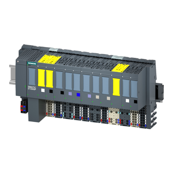
Product overview Properties Article number 6ES7155-6AU00-0DN0 (interface module IM 155-6 PN HS and server module) View of the module Figure 2-1 View of the IM 155-6 PN HS interface module and the server module IM 155-6 PN HS interface module (6ES7155-6AU00-0DN0) Manual, 09/2016, A5E34928647-AA... - Page 12 Product overview 2.1 Properties Properties The module has the following properties: ● Connects the ET 200SP distributed I/O system with PROFINET IO ● High-speed applications as of 125 µs ● Isochronous mode according to PROFINET V2.3 ● Supply voltage 1L+ 24 V DC (SELV/PELV). ●...
- Page 13 ● Reference identification label A detailed list of the available accessories can be found in the system manual ET 200SP distributed I/O system (http://support.automation.siemens.com/WW/view/en/58649293). Server module The server module is included in the scope of delivery of the interface module and is available separately as a spare part.
- Page 14 Product overview 2.1 Properties First BaseUnit of an ET 200SP in the configuration The interface modules support dark-colored BaseUnits in slot 1. This means that modules without a connection to the integrated voltage buses P1 and P2 can be configured starting with slot 1.
-
Page 15: Functions
Product overview 2.2 Functions Functions PROFINET IO The interface module supports the following PROFINET IO functions: ● Integrated switch with 2 ports ● Supported Ethernet services: ping, arp, network diagnostics (SNMP)/MIB-2, LLDP-MIB and MRP-MIB ● Port diagnostics ● Disabling ports ●... - Page 16 Product overview 2.2 Functions Requirements The table below shows the software requirements for a configuration with the IM 155-6 PN HS interface module: Table 2- 1 Version dependencies of other module functions Function Product version Firmware version Configuration software of the module of the module as Configuration STEP 7 as of...
- Page 17 You can find more information on this topic in the STEP 7 online help and ● As of STEP 7 V14, in the PROFINET with STEP 7 V14 (http://support.automation.siemens.com/WW/view/en/49948856) function manual ● As of STEP 7 V5.5, in the PROFINET System Description (http://support.automation.siemens.com/WW/view/en/19292127) system manual...
- Page 18 You can find more information on this topic in the STEP 7 online help and ● As of STEP 7 V14, in the PROFINET with STEP 7 V14 (http://support.automation.siemens.com/WW/view/en/49948856) function manual ● As of STEP 7 V5.5, in the PROFINET System Description (http://support.automation.siemens.com/WW/view/en/19292127) system manual...
- Page 19 You can find more information on this topic in the STEP 7 online help and ● As of STEP 7 V14, in the PROFINET with STEP 7 V14 (http://support.automation.siemens.com/WW/view/en/49948856) function manual ● As of STEP 7 V5.5, in the PROFINET System Description (http://support.automation.siemens.com/WW/view/en/19292127) system manual...
- Page 20 You can find more information on this topic in the STEP 7 online help and ● As of STEP 7 V14, in the PROFINET with STEP 7 V14 (http://support.automation.siemens.com/WW/view/en/49948856) function manual ● As of STEP 7 V5.5, in the PROFINET System Description (http://support.automation.siemens.com/WW/view/en/19292127) system manual...
- Page 21 In a replacement scenario, any IO device or BusAdapter in operation must be reset to its delivery state via "Reset to factory settings" (see the system manual ET 200SP distributed I/O system (http://support.automation.siemens.com/WW/view/en/58649293)). Media redundancy (MRP) Function for safeguarding communication and system availability. A ring topology ensures that an alternative communication path is made available if a transmission route fails.
- Page 22 You can find more information on this topic in the STEP 7 online help and: ● As of STEP 7 V14, in the PROFINET with STEP 7 V14 (http://support.automation.siemens.com/WW/view/en/49948856) function manual Value status The IM 155-6 PN HS interface module supports I/O modules with value status.
-
Page 23: Profienergy
PROFIenergy (for PROFINET) reduces the energy consumption by using PROFIenergy commands during production-free periods. Reference You can find more information on PROFIenergy in the ● I/O modules (http://support.automation.siemens.com/WW/view/en/55679691/133300) manual ● PROFINET with STEP 7 V14 (http://support.automation.siemens.com/WW/view/en/49948856) function manual ● PROFINET System Description (http://support.automation.siemens.com/WW/view/en/19292127) system manual... -
Page 24: Use Of Fail-Safe Modules
Properties The interface module IM 155-6 PN HS supports the use of fail-safe modules. Reference You can find more information in the ET 200SP distributed I/O system (http://support.automation.siemens.com/WW/view/en/58649293) system manual. 2.2.4 Multi Hot Swap Properties You can remove and insert any number of I/O modules during operation. The interface module and the inserted I/O modules remain in operation. -
Page 25: Connecting
Connecting Terminal assignment 24 V DC supply voltage The table below shows the signal names and descriptions of the pin assignment of the 24 V DC supply voltage. Table 3- 1 Pin assignment 24 V DC supply voltage View Signal name Description Connector IM connection... - Page 26 Connecting 3.1 Terminal assignment PROFINET IO with BusAdapter BA 2×RJ45 The following table shows the signal name and description of the pin assignment of the BusAdapter BA 2×RJ45. Table 3- 2 PROFINET IO pin assignment with BusAdapter BA 2×RJ45 View Signal name Description Transmit data +...
- Page 27 Connecting 3.1 Terminal assignment PROFINET IO with BusAdapter BA 2×SCRJ The following table shows the signal names and description of the pin assignment for the BA 2×SCRJ BusAdapter. Table 3- 4 PROFINET IO pin assignment with BusAdapter BA 2×SCRJ View Signal Description name...
- Page 28 Connecting 3.1 Terminal assignment PROFINET IO with BusAdapter BA SCRJ/RJ45 The following table shows the signal names and description of the pin assignment for the BA SCRJ/RJ45 BusAdapter. Table 3- 6 PROFINET IO pin assignment with BusAdapter BA SCRJ/RJ45 View Signal name Description ①...
- Page 29 Connecting 3.1 Terminal assignment PROFINET IO with BusAdapter BA SCRJ/FC The following table shows the signal names and description of the pin assignment for the BA SCRJ/FC BusAdapter. The pin assignment for the BA SCRJ/FC BusAdapter is shown individually for a clearer overview.
- Page 30 Receive data + RD_N Receive data - Reference You can find more information on accessories and how to connect the interface module in the System Manual ET 200SP distributed I/O system (http://support.automation.siemens.com/WW/view/en/58649293). IM 155-6 PN HS interface module (6ES7155-6AU00-0DN0) Manual, 09/2016, A5E34928647-AA...
-
Page 31: Schematic Circuit Diagram
Connecting 3.2 Schematic circuit diagram Schematic circuit diagram The following figure shows the block diagram of the interface module IM 155-6 PN HS. ① Switch 24 V DC supply voltage ② ET 200SP backplane bus interface and Ground electronics ③ Backplane bus LK 1,2 Link TX/RX LED (green) -
Page 32: Parameters/Address Space
196 from the user program in order for the ET 200SP distributed I/O system to operate the I/O modules. Reference You can find more information in the ET 200SP distributed I/O system (http://support.automation.siemens.com/WW/view/en/58649293) system manual and in the STEP 7 online help. IM 155-6 PN HS interface module (6ES7155-6AU00-0DN0) Manual, 09/2016, A5E34928647-AA... -
Page 33: Substitute Value Behavior
IM 155-6 PN HS. You can find information on the status of the supply voltage L+ of the I/O modules in the Server module (http://support.automation.siemens.com/WW/view/en/63257531) manual. IM 155-6 PN HS interface module (6ES7155-6AU00-0DN0) Manual, 09/2016, A5E34928647-AA... -
Page 34: Interrupts, Diagnostics, Error, And System Messages
Interrupts, diagnostics, error, and system messages Status and error displays LED displays The following figure shows the LED displays on the interface module and BusAdapter. ① RN (green) ② ER (red) ③ MT (yellow) ④ PWR (green) ⑤ MT2 (yellow) (SCRJ port) ⑥... - Page 35 Hardware or firmware defective (the Run a firmware update. If the error persists, LEDs LK1 and LK2 of the PROFINET contact Siemens Industry Online Support. interface do not flash). Replace the interface module. Not rele- Configuration error on backplane bus...
- Page 36 Interrupts, diagnostics, error, and system messages 5.1 Status and error displays PWR LED on the interface module Table 5- 2 Status display of the PWR LED PWR LED Meaning Remedy Supply voltage not present or too small Check the supply voltage. Supply voltage present LK1/LK2 and MT1/MT2 LEDs on the BusAdapter Table 5- 3...
- Page 37 Interrupts, diagnostics, error, and system messages 5.1 Status and error displays LED display of configuration errors Configuration errors of the ET 200SP distributed I/O system are output on the interface module by the ER (red) and MT (yellow) LEDs. The following configuration errors are indicated by the LEDs: ●...
-
Page 38: Interrupts
Interrupts, diagnostics, error, and system messages 5.2 Interrupts Error display The following table shows the possible causes of error that can occur. Table 5- 5 Error display Error type Error location Cause of error Remedy (MT) (ER/MT) Check the configuration Missing server module •... -
Page 39: Triggering Of A Diagnostics Interrupt
CPU S7-1500, the CPU web server and the HMI device. For more information on system diagnostics, refer to the System Diagnostics function manual. (http://support.automation.siemens.com/WW/view/en/59192926). 5.2.1 Triggering of a diagnostics interrupt Triggering of a diagnostics interrupt For an incoming or outgoing event (e.g. -
Page 40: Triggering A Swapping Interrupt
Interrupts, diagnostics, error, and system messages 5.3 Alarms 5.2.3 Triggering a swapping interrupt Triggering a remove/insert interrupt In the event of a remove/insert interrupt, the CPU interrupts processing of the user program and processes the remove/insert interrupt (OB 83). The event which led to the interrupt is entered in the start information of the remove/insert interrupt (OB 83). - Page 41 Additional information on the data records for PROFINET IO The structure of the diagnostic data records and programming examples are available in the Programming Manual From PROFIBUS DP to PROFINET IO (http://support.automation.siemens.com/WW/view/en/19289930) and in Example application (http://support.automation.siemens.com/WW/view/en/24000238). Causes of error and troubleshooting...
-
Page 42: Maintenance Events
Interrupts, diagnostics, error, and system messages 5.3 Alarms 5.3.1 Maintenance events Triggering of a maintenance event The PROFINET IO interfaces of the interface module support the diagnostic concept and maintenance concept in PROFINET IO according to the IEC 61158-6-10 standard. The goal is to detect and remove potential problems as soon as possible. -
Page 43: Channel Diagnostics
Interrupts, diagnostics, error, and system messages 5.3 Alarms 5.3.2 Channel diagnostics Function Channel-related diagnostics provides information about channel faults in modules. Channel faults are mapped as channel diagnostics data in IO diagnostics data records. The data record is read using the instruction "RDREC". Structure of the diagnostics data records The data records supported by the ET 200SP distributed I/O system are based on the standard PROFINET IO - Application Layer Service Definition V2.3. -
Page 44: Invalid Configuration States Of The Et 200Sp On Profinet Io
Interrupts, diagnostics, error, and system messages 5.3 Alarms 5.3.3 Invalid configuration states of the ET 200SP on PROFINET IO Invalid configuration states The following invalid configuration states of the ET 200SP distributed I/O system lead to the failure of the IO device or prevent the exchange of user data with the I/O modules. ●... -
Page 45: Stop Of The Io Controller And Recovery Of The Io Device
Interrupts, diagnostics, error, and system messages 5.3 Alarms 5.3.5 STOP of the IO controller and recovery of the IO device STOP of the SIMATIC IO controller Diagnostics frames received from the IO device while the IO controller is in STOP do not initiate a call of any corresponding OBs when the IO controller goes into RUN. -
Page 46: Compatibility
Compatibility Status of the supply voltage Load voltage diagnostics are only valid if the station started up with a valid and complete configuration. ● For modules in the following table without a parameter assignment, the status of the supply voltage is always signaled as "1" regardless of the actual status of the supply voltage. -
Page 47: Technical Specifications
Technical specifications Technical specifications of the IM 155-6 PN HS 6ES7155-6AU00-0DN0 General information Product type designation ET 200SP, IM 155-6 PN HS with server module Firmware version V4.0 Product function I&M data Yes; I&M0 to I&M3 Engineering with STEP 7 TIA Portal can be configured/integrated As of STEP 7 V14 as of version STEP 7 can be configured/integrated as of version V5.5 SP4 or higher... - Page 48 Technical specifications 6ES7155-6AU00-0DN0 Hardware configuration Racks Modules per rack, max. Submodules Number of submodules per station, max. Interfaces Number of PROFINET interfaces 1; 2 ports (switch) 1st interface Interface hardware Number of ports Integrated switch BusAdapter (PROFINET) Yes; usable BusAdapters: BA 2x RJ45, BA 2x FC, BA 2x SCRJ, BA SCRJ / RJ45, BA SCRJ / FC, BA 2x LC, BA LC / RJ45, BA LC / FC Protocols...
- Page 49 Technical specifications 6ES7155-6AU00-0DN0 Open IE communication TCP/IP SNMP LLDP Isochronous mode Isochronous mode (application synchronized up to terminal) Constant bus cycle time Shortest clock pulse 125 µs Longest clock pulse 4 ms Bus cycle time (TDP), min. 125 µs Jitter, max. 0.25 µs Interrupts/diagnostics/status information Status display...
- Page 50 Technical specifications Technical specifications of the BusAdapter BA 2×RJ45 Table 7- 1 Technical specifications of the BusAdapter BA 2×RJ45 6ES7193-6AR00-0AA0 Interfaces PROFINET IO Number of PROFINET interfaces RJ45 Yes; 2 x FC (FastConnect) SCRJ Cable length 100 m Copper cables •...
- Page 51 Technical specifications Technical specifications of the BusAdapter BA 2×SCRJ Table 7- 3 Technical specifications of the BusAdapter BA 2×SCRJ 6ES7193-6AP00-0AA0 Interfaces PROFINET IO Number of PROFINET interfaces 1; 2 ports (switch) SCRJ FO RJ45 FC (FastConnect) SCRJ Cable length 100 m •...
- Page 52 Technical specifications Technical specifications of the BusAdapter BA SCRJ/RJ45 Table 7- 4 Technical specifications of the BusAdapter BA SCRJ/RJ45 6ES7193-6AP20-0AA0 Interfaces PROFINET IO Number of PROFINET interfaces 1; 2 ports (SCRJ + RJ45) RJ45 Yes; 1x FC (FastConnect) SCRJ Cable length 100 m •...
- Page 53 Technical specifications Technical specifications of the BusAdapter BA SCRJ/FC Table 7- 5 Technical specifications of the BusAdapter BA SCRJ/FC 6ES7193-6AP40-0AA0 Interfaces PROFINET IO Number of PROFINET interfaces 1; 2 ports (SCRJ + FC) RJ45 FC (FastConnect) Yes; 1x SCRJ Cable length 100 m •...
- Page 54 Technical specifications Technical specifications of the BusAdapter BA 2×LC Table 7- 6 Technical specifications of the BusAdapter BA 2×LC 6ES7193-6AG00-0AA0 Interfaces Number of PROFINET interfaces 1; 2 ports (switch) LC multimode glass-fiber PROFINET IO RJ45 FC (FastConnect) SCRJ Cable length 3 km Multimode gradient-index fiber 50/125 µm •...
- Page 55 Technical specifications Technical specifications of the BusAdapter BA LC/RJ45 Table 7- 7 Technical specifications of the BusAdapter BA LC/RJ45 6ES7193-6AG20-0AA0 Interfaces Number of PROFINET interfaces 1; 2 ports (switch) LC / RJ45 PROFINET IO RJ45 Yes; 1x FC (FastConnect) SCRJ Cable length 100 m Copper cables...
- Page 56 Technical specifications Technical specifications of the BusAdapter BA LC/FC Table 7- 8 Technical specifications of the BusAdapter BA LC/FC 6ES7193-6AG40-0AA0 Interfaces Number of PROFINET interfaces PROFINET IO RJ45 FC (FastConnect) Yes; 1x SCRJ Cable length 100 m Copper cables • 3 km Multimode gradient-index fiber 50/125 µm •...
-
Page 57: Dimensional Drawing
Dimensional drawing This appendix contains a dimension drawing of the module installed on a mounting rail. Always observe the specified dimensions for installation in cabinets, control rooms, etc. Figure A-1 Dimension drawing of the IM 155-6 PN HS interface module (front and side view) IM 155-6 PN HS interface module (6ES7155-6AU00-0DN0) Manual, 09/2016, A5E34928647-AA...