Table of Contents
Advertisement
Advertisement
Table of Contents
Troubleshooting

Related Manuals for Mitsubishi Q170MCPU


Summary of Contents for Mitsubishi Q170MCPU
-
Page 2: Safety Precautions
SAFETY PRECAUTIONS (Please read these instructions before using this equipment.) Before using this product, please read this manual and the relevant manuals introduced in this manual carefully and pay full attention to safety to handle the product correctly. These precautions apply only to this product. Refer to the Users manual of the QCPU module to use for a description of the PLC system safety precautions. - Page 3 For Safe Operations 1. Prevention of electric shocks DANGER Never open the front case or terminal covers while the power is ON or the unit is running, as this may lead to electric shocks. Never run the unit with the front case or terminal cover removed. The high voltage terminal and charged sections will be exposed and may lead to electric shocks.
- Page 4 3. For injury prevention CAUTION Do not apply a voltage other than that specified in the instruction manual on any terminal. Doing so may lead to destruction or damage. Do not mistake the terminal connections, as this may lead to destruction or damage. Do not mistake the polarity ( + / - ), as this may lead to destruction or damage.
- Page 5 CAUTION The dynamic brakes must be used only on errors that cause the forced stop, emergency stop, or servo OFF. These brakes must not be used for normal braking. The brakes (electromagnetic brakes) assembled into the servomotor are for holding applications, and must not be used for normal braking.
- Page 6 CAUTION Set the sequence function program capacity setting, device capacity, latch validity range, I/O assignment setting, and validity of continuous operation during error detection to values that are compatible with the system application. The protective functions may not function if the settings are incorrect.
- Page 7 CAUTION Always install the servomotor with reduction gears in the designated direction. Failing to do so may lead to oil leaks. Store and use the unit in the following environmental conditions. Conditions Environment Motion controller/Servo amplifier Servomotor Ambient 0°C to +40°C (With no freezing) According to each instruction manual.
- Page 8 (4) Wiring CAUTION Correctly and securely wire the wires. Reconfirm the connections for mistakes and the terminal screws for tightness after wiring. Failing to do so may lead to run away of the servomotor. After wiring, install the protective covers such as the terminal covers to the original positions. Do not install a phase advancing capacitor, surge absorber or radio noise filter (option FR-BIF) on the output side of the servo amplifier.
- Page 9 (6) Usage methods CAUTION Immediately turn OFF the power if smoke, abnormal sounds or odors are emitted from the Motion controller, servo amplifier or servomotor. Always execute a test operation before starting actual operations after the program or parameters have been changed or after maintenance and inspection. Do not attempt to disassemble and repair the units excluding a qualified technician whom our company recognized.
- Page 10 (8) Maintenance, inspection and part replacement CAUTION Perform the daily and periodic inspections according to the instruction manual. Perform maintenance and inspection after backing up the program and parameters for the Motion controller and servo amplifier. Do not place fingers or hands in the clearance when opening or closing any opening. Periodically replace consumable parts such as batteries according to the instruction manual.
- Page 11 When considering this product for operation in special applications such as machinery or systems used in passenger transportation, medical, aerospace, atomic power, electric power, or submarine repeating applications, please contact your nearest Mitsubishi sales representative. Although this product was manufactured under conditions of strict quality control, you are strongly advised to install safety devices to forestall serious accidents when it is used in facilities where a breakdown in the product is likely to cause a serious accident.
-
Page 12: Revisions
This manual confers no industrial property rights or any rights of any other kind, nor does it confer any patent licenses. Mitsubishi Electric Corporation cannot be held responsible for any problems involving industrial property rights which may occur as a result of using the contents noted in this manual. -
Page 13: Table Of Contents
2.1.1 Q170MCPU System overall configuration..................2- 3 2.1.2 Q170MCPU System internal configuration ..................2- 4 2.1.3 Function explanation of the Q170MCPU Motion controller ............. 2- 5 2.1.4 Restrictions on Motion controller ...................... 2- 6 2.2 Checking Serial Number and Operating System Software Version............2- 8 2.2.1 Checking serial number ........................ - Page 14 4. INSTALLATION AND WIRING 4- 1 to 4-28 4.1 Module Installation ........................... 4- 1 4.1.1 Instructions for handling ........................4- 1 4.1.2 Instructions for mounting the modules ..................... 4- 3 4.1.3 Installation and removal of module to the base unit................. 4- 9 4.1.4 Mounting and removal of the battery holder..................
- Page 15 APPENDICES APP- 1 to APP-54 APPENDIX 1 Differences Between Q170MCPU and Q173DCPU/Q172DCPU ........APP- 1 APPENDIX 1.1 Differences of devices ....................APP- 2 APPENDIX 1.2 Differences of parameters...................APP- 3 APPENDIX 1.3 Differences of programs....................APP- 3 APPENDIX 1.4 Differences of error codes...................APP- 5 APPENDIX 1.5 Differences of peripheral device interface ..............APP- 6...
-
Page 16: About Manuals
Manual Number Manual Name (Model Code) Q170MCPU Motion controller User's Manual This manual explains specifications of the Q170MCPU Motion controller, Q172DLX Servo external signal IB-0300156 interface module, Q173DPX Manual pulse generator interface module, Servo amplifiers, SSCNET (1XB941) cables, and the maintenance/inspection for the system, trouble shooting and others. - Page 17 (2) PLC Manual Number Manual Name (Model Code) QCPU User's Manual (Hardware Design, Maintenance and Inspection) This manual explains the specifications of the QCPU modules, power supply modules, base units, SH-080483ENG extension cables, memory card battery, and the maintenance/inspection for the system, trouble shooting, (13JR73) error codes and others.
- Page 18 (3) Servo amplifier Manual Number Manual Name (Model Code) SSCNET Compatible MR-J3- B Servo amplifier Instruction Manual SH-030051 This manual explains the I/O signals, parts names, parameters, start-up procedure and others for (1CW202) MR-J3- B Servo amplifier. (Optional) SSCNET Compatible Linear Servo MR-J3- B-RJ004 Servo amplifier Instruction Manual SH-030054 This manual explains the I/O signals, parts names, parameters, start-up procedure and others for Linear (1CW943)
- Page 19 MEMO A - 18...
-
Page 20: Overview
1.1 Overview This User's Manual describes the hardware specifications and handling methods of the Motion Controller Q170MCPU for the Q series PLC Multiple CPU system. The Manual also describes those items related to the specifications of the option module for the Motion controller, Manual pulse generator and cables. - Page 21 1 OVERVIEW REMARK For information about the each module, design method for program and parameter, refer to the following manuals. Item Reference Manual PLC CPU area, peripheral devices for PLC program design, MELSEC-Q series PLC Manuals, I/O modules and intelligent function module Manual relevant to each module Operation method for MT Developer2 Help of each software...
-
Page 22: Comparison Between Q170Mcpu And Q173Dcpu/Q172Dcpu
1 OVERVIEW 1.2 Comparison between Q170MCPU and Q173DCPU/Q172DCPU (1) Comparison of hardware Item Q170MCPU Q173DCPU Q172DCPU Power supply Built-in (24VDC) Power supply module (24VDC, 100VAC, 200VAC) PLC CPU area Q03UDCPU or equivalent (20k steps) QnUD(E)(H)CPU Program capacity 20k steps 30k to 260k steps LD instruction processing speed 0.02µs... - Page 23 1 OVERVIEW (2) Comparison of Motion control specifications Item Q170MCPU Q173DCPU Q172DCPU Number of control axes Up to 16 axes Up to 32 axes Up to 8 axes 0.44ms/ 1 to 6 axes 0.44ms/ 1 to 6 axes 0.44ms/ 1 to 6 axes SV13 0.88ms/ 7 to 18 axes...
- Page 24 1 OVERVIEW (3) Comparison of Motion SFC performance specifications Item Q170MCPU Q173DCPU/Q172DCPU Code total (Motion SFC chart + Operation control + 543k bytes Motion SFC program Transition) capacity Text total 484k bytes (Operation control + Transition) Number of Motion SFC programs 256 (No.0 to 255)
- Page 25 1 OVERVIEW (4) Comparison of Mechanical system program specifications Item Q170MCPU Q173DCPU Q172DCPU Virtual servomotor Drive module Synchronous encoder Roller Control units mm, inch Output Ball screw module Rotary table degree mm, inch, PLS Program language Dedicated instructions (Servo program + mechanical system program)
- Page 26 1 OVERVIEW (5) Comparison of PLC CPU area control and performance Item Q170MCPU Q173DCPU/Q172DCPU PLC CPU area Q03UDCPU or equivalent (20k steps) QnUD(E)(H)CPU Control method Sequence program control method I/O control mode Refresh mode Relay symbol language (ladder), logic symbolic language (list),...
- Page 27 1 OVERVIEW Comparison of PLC CPU area control and performance (Continued) Item Q170MCPU Q173DCPU/Q172DCPU Number of extension 1 extension (Q52B/Q55B usable) 7 extensions • Extension base unit use: Connection after the extension base Extension base unit unit of stage 1...
-
Page 28: System Configuration
2 SYSTEM CONFIGURATION 2. SYSTEM CONFIGURATION This section describes the Motion controller (Q170MCPU) system configuration, precautions on use of system and configured equipments. 2.1 Motion System Configuration (1) Equipment configuration in Q170MCPU system Extension of the Q series module Forced stop input cable... - Page 29 2 SYSTEM CONFIGURATION (2) Peripheral device configuration for the Q170MCPU The following (a)(b)(c) can be used. (a) USB configuration (b) RS-232 configuration (c) Ethernet configuration Motion controller Motion controller Motion controller (Q170MCPU) (Q170MCPU) (Q170MCPU) RS-232 communication cable USB cable Ethernet cable...
-
Page 30: Q170Mcpu System Overall Configuration
2 SYSTEM CONFIGURATION 2.1.1 Q170MCPU System overall configuration Motion controller Q170MCPU USB/RS-232 PERIPHERAL I/F Panel personal computer Personal computer IBM PC/AT SSCNET cable (MR-J3BUS M(-A/-B) DC24V Forced stop input cable SSCNET (Q170DEMICBL M) Forced stop input (24VDC) MR-J3- B model Servo amplifier, Up to 16 axes... -
Page 31: Q170Mcpu System Internal Configuration
2.1.2 Q170MCPU System internal configuration (1) What is Multiple CPU system for Q170MCPU ? A Multiple CPU system for Q170MCPU is a system in which between the PLC CPU area and Motion CPU area are connected with the Multiple CPU high speed bus in order to control the I/O modules and intelligent function modules. -
Page 32: Function Explanation Of The Q170Mcpu Motion Controller
(c) It is possible to execute a download of servo parameters to servo amplifier, servo ON/OFF to servo amplifier and position commands, etc. by connecting between the Q170MCPU and servo amplifier with SSCNET cable. (d) It is possible to select the servo control functions/programming languages by installing the corresponding operating system software in the Q170MCPU. -
Page 33: Restrictions On Motion Controller
(1) Only extension base unit (Q52B/Q55B) of type not requiring power supply module can be used. (2) Q170MCPU Multiple CPU system is composed of the PLC CPU area (CPU No.1 fixed) and Motion CPU area (CPU No.2 fixed). Other CPU (CPU No.3, CPU No.4) cannot be set. - Page 34 (17) When the extension base units are used, make sure to configure the modules so that the total current consumption of the Q170MCPU and individual modules on the extension base do not exceed the 5VDC output capacity of Q170MCPU power supply.
-
Page 35: Checking Serial Number And Operating System Software Version
Checking for the serial number of Motion controller and Motion module, and the operating system software version are shown below. 2.2.1 Checking serial number (1) Motion controller (Q170MCPU) (a) Rating plate The rating plate is situated on the side face of the Motion controller. - Page 36 Q172DLX 12/24VDC 2/4mA Serial number B86054999 SERIAL 80M1 IND. CONT. EQ. US LISTED CLASS2 ONLY MITSUBISHI ELECTRIC CTRL JAPAN Q172DLX Serial number B86054999 REMARK The serial number display was corresponded from the Motion modules manufactured in early April 2008. 2 - 9...
-
Page 37: Checking Operating System Software Version
2 SYSTEM CONFIGURATION 2.2.2 Checking operating system software version The operating system software version can be checked on the system monitor screen in GX Developer. Select [Product Inf. List] button on the system monitor screen displayed on [Diagnostics] – [System monitor] of GX Developer. Serial number of Motion controller Operating system software version... -
Page 38: System Configuration Equipment
(Attachment battery (Q6BAT), external I/O connector, 24VDC power supply connector and connector for forced stop input cable) • Motion CPU area Motion controller Q170MCPU Up to 16 axes control, Operation cycle 0.44[ms] or more, Servo program capacity 16k steps • PLC CPU area Program capacity 20k steps, LD instruction processing speed 0.02μs... - Page 39 (Note-3) : 5VDC internal current consumption of shared equipments with PLC might be changed. Be sure to refer to the MELSEC-Q series PLC Manuals. (Note-4) : Please contact your nearest Mitsubishi sales representative for the cable of less than 30m(98.43ft.). 2 - 12...
- Page 40 2 SYSTEM CONFIGURATION (2) PLC module which can be controlled by Motion CPU area Current consumption Part name Model name Description Remark (Note-1) 5VDC[A] 0.05 QX10 100-120VAC, 7-8mA, 16 points, Terminal block (TYP, All points ON) 0.05 QX40 24VDC/4mA, Positive common, 16 points, Terminal block (TYP, All points ON) High response type, 24VDC/6mA, Positive common, 0.06...
- Page 41 2 SYSTEM CONFIGURATION PLC module which can be controlled by Motion CPU area(continued) Current consumption Part name Model name Description Remark (Note-1) 5VDC[A] 24VDC Positive common: 32 points 12-24VDC/0.1A Output Sink type: 32 points, Connector, 0.13 (Note-2) QH42P Provided (Thermal protectors, protector against short (TYP, All points ON) Input/Output DC Input/...
- Page 42 2 SYSTEM CONFIGURATION (6) Programming software packages (a) Motion controller engineering environment Part name Model name MELSOFT MT Works2 SW1DNC-MTW2-E (Note-1 (MT Developer2 (Note-1) : This software is included in Motion controller engineering environment "MELSOFT MT Works2". (b) PLC software package Model name Software package GX Developer...
-
Page 43: General Specifications
2 SYSTEM CONFIGURATION 2.4 General Specifications General specifications of the Motion controller are shown below. Item Specification Operating ambient temperature 0 to 55°C (32 to 131°F) (Note-3) Storage ambient temperature -25 to 75°C (-13 to 167°F) Operating ambient humidity 5 to 95% RH non-condensing Storage ambient humidity 5 to 95% RH... -
Page 44: Specifications Of Equipment
POINTS (Note-1) : Input power supply Q170MCPU is rated for use with a 24VDC input power only. The Q170MCPU breaks down when 28VDC or more input. (Note-2) : Select 24VDC power supply and electric wire within the range of 21.6 to 26.4VDC including any input ripple or spike voltage measured at the... - Page 45 2 SYSTEM CONFIGURATION (2) Motion control specifications/performance specifications (a) Motion control specifications Item Specification Number of control axes Up to 16 axes 0.44ms/ 1 to 6 axes SV13 0.88ms/ 7 to 16 axes Operation cycle 0.44ms/ 1 to 4 axes (default) SV22 0.88ms/ 5 to 12 axes...
- Page 46 2 SYSTEM CONFIGURATION Motion control specifications (continued) Item Specification All clear function Provided Remote operation Remote RUN/STOP, Remote latch clear Digital oscillation function Provided Made compatible by setting battery to servo amplifier. Absolute position system (Possible to select the absolute data method or incremental method for each axis) Number of SSCNET 1 system (Note-1)
- Page 47 2 SYSTEM CONFIGURATION (b) Motion SFC performance specifications Item Specification Code total (Motion SFC chart + Operation control + 543k bytes Motion SFC program capacity Transition) Text total 484k bytes (Operation control + Transition) Number of Motion SFC programs 256 (No.0 to 255) Motion SFC chart size/program Up to 64k bytes (Included Motion SFC chart comments) Number of Motion SFC steps/program...
- Page 48 2 SYSTEM CONFIGURATION (3) PLC control specifications Item Specification Program capacity, number of I/O points and number of extensions PLC CPU area were limited to Q03UDCPU Control method Sequence program control method I/O control mode Refresh mode Relay symbol language (ladder), logic symbolic language (list), Sequence control language MELSAP3 (SFC), MELSAP-L, Structured text (ST) LD instruction...
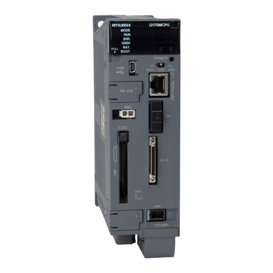
- Page 49 1 • Extension base unit not use : Direct bus connection to Motion controller PC type when program is made by GX Developer Q03UDCPU (4) Q170MCPU names of parts With front cover open, and battery holder remove Side face...
- Page 50 2 SYSTEM CONFIGURATION Name Application 1) 7-segment LED Indicates the operating status and error information. Rotary function select 1 switch • Set the operation mode. (SW1) (Normal operation mode, Installation mode, Mode operated by ROM, etc) • Each switch setting is 0 to F. Rotary function select 2 switch (Factory default in SW1 "A", SW2 "0"...
- Page 51 2 SYSTEM CONFIGURATION Name Application Indicates the operating status of the PLC CPU area. • ON : Detection of self-diagnosis error which will not stop operation, except battery error. (When operation continued at error detection is set in the 12) "ERR." LED parameter setting.) •...
- Page 52 2 SYSTEM CONFIGURATION (5) 7-segment LED display The LED displays/flashes in the combination with errors. Item 7-segment LED Remark It takes about 10 seconds to initialize Start Initializing (RUN/STOP display). Normal " " remains flashing Normal operation Steady "INS" display, Mode to install the operating system software via Installation mode "...
- Page 53 2 SYSTEM CONFIGURATION Item 7-segment LED Remark " AL" flashes 3 times Steady " A1" display Setting error of the Multiple CPU system (Self-diagnosis error) Self diagnostic error Refer to the "Q173DCPU/Q172DCPU Motion (Error related for Multiple CPU) controller Programming Manual (COMMON)" for 4-digits error code is details.
- Page 54 2 SYSTEM CONFIGURATION (7) Operation mode (a) Rotary switch setting and operation mode Rotary switch setting Operation mode Any setting (Except C) Installation mode Mode operated by RAM Mode operated by ROM Ethernet IP address display mode (Note) Any setting SRAM clear (Note) : The data (Refer to Section 6.5) of RAM built-in Motion controller are cleared.
- Page 55 2 SYSTEM CONFIGURATION (c) Ethernet IP address display mode overview 7-segment LED Operation overview (Note) IP address (ex. 192.168.3.39) Subnet mask pattern (Note) (ex. 255.255.255.0) Default router IP (Note) address (ex. 192.168.3.1) Link status Disconnect Connect (10Mbps) Full duplex Connect (100Mbps) Half duplex (Note): When the Ethernet parameters are not written in the Motion controller, the addresses...
- Page 56 2 SYSTEM CONFIGURATION (9) 24VDC power supply connector (a) The pin layout of the 24VDC power supply connector 24VDC power supply is supplied from the 24VDC power supply connector of the front face of the Motion controller. The pins layout (from front view) and connection of the 24VDC power supply connector is shown below.
- Page 57 Q55B QX40 Q173D QY40P QJ71 Q62DA LP21-25 MR-HDP01 MR-HDP01 • 5VDC current consumption of each module Q170MCPU : 2.00 [A] QY40P : 0.065 [A] QX40 : 0.05 [A] QJ71LP21-25 : 0.55 [A] Q173DPX : 0.38 [A] Q62DA : 0.33 [A] MR-HDP01 : 0.06 [A]...
-
Page 58: Extension Base Unit And Extension Cable
2 SYSTEM CONFIGURATION 2.5.2. Extension base unit and extension cable This section describes the specifications of the extension cables for the base units (Extension base unit), and the specification standards of the extension base unit. 5VDC internal current consumption of base unit might be changed. Be sure to refer to the MELSEC-Q series PLC Manuals. - Page 59 2 SYSTEM CONFIGURATION (3) Names of parts of the extension base unit Names of parts of the extension base unit are described below. (a) Extension base unit (Q52B, Q55B) I/O0 I/O1 I/O2 I/O3 I/O4 Name Application Extension cable Connector for connecting an extension cable (for signal communications with the extension connector base unit) Protective cover of extension cable connector.
- Page 60 It is not mandatory to match the I/O device PX/PY No.s used in the Motion program with the PLC I/O No.s; but it is recommended to make them match as much as possible. The following figure shows an example of I/O allocation. Q170MCPU QX41 Q62DA QX41...
-
Page 61: Q172Dlx Servo External Signals Interface Module
2 SYSTEM CONFIGURATION 2.5.3 Q172DLX Servo external signals interface module Q172DLX receives external signals (servo external signals) required for positioning control. (1) Q172DLX name of parts Q172DLX CTRL Q172DLX Name Application Hook used to fix the module to the base unit. Module fixing hook (Single-motion installation) Display the servo external input status from the external... - Page 62 2 SYSTEM CONFIGURATION (2) Performance specifications (a) Module specifications Item Specifications Number of I/O occupying points 32 points(I/O allocation: Intelligent, 32 points) Internal current consumption(5VDC) [A] 0.06 98(H) 27.4(W) 90(D) Exterior dimensions [mm(inch)] (3.86(H) 1.08(W) 3.54(D) ) Mass [kg] 0.15 (b) Input Item Specifications...
- Page 63 2 SYSTEM CONFIGURATION (3) Connection of servo external signals interface module (a) Servo external signals There are the following servo external signals. (Upper stroke limit is limit value of address increase direction/lower stroke limit is limit value of an address decrease direction.) The Q172DLX is assigned a set of input No.s per axis.
- Page 64 2 SYSTEM CONFIGURATION (b) The pin layout of the CTRL connector Use the CTRL connector at the Q172DLX module front to connect the servo external signals. The pin layout of the Q172DLX CTRL connector viewed from the front is shown below. CTRL connector Pin No.
- Page 65 2 SYSTEM CONFIGURATION (4) Interface between CTRL connector and servo external signal Input or Signal name Wiring example Internal circuit Specification Description PIN No. Output FLS1 Supply voltage FLS2 12 to 24 VDC (10.2 to 26.4 VDC, FLS3 Upper stroke stabilized power FLS4 5.6k...
-
Page 66: Q173Dpx Manual Pulse Generator Interface Module
2 SYSTEM CONFIGURATION 2.5.4 Q173DPX Manual pulse generator interface module Q173DPX receive signals required for Manual pulse and Incremental synchronous encoder (Voltage-output/Open-collector type/Differential-output type) input. (1) Q173DPX name of parts Q173DPX PLS.A PLS.B TREN PULSER Q173DPX Name Application Hook used to fix the module to the base unit. Module fixing hook (Single-motion installation) Display the input status from the external equipment. - Page 67 2 SYSTEM CONFIGURATION Name Application Detection setting of TREN1 signal Dip switch 1 SW1 SW2 TREN is detected at leading edge of TREN signal. Dip switch 2 TREN is detected at trailing edge (Note-1) Dip switches of TREN signal. Detection setting of TREN2 signal Dip switch 3 SW3 SW4 TREN is detected at leading...
- Page 68 2 SYSTEM CONFIGURATION (2) Performance specifications (a) Module specifications Item Specifications Number of I/O occupying points 32 points(I/O allocation: Intelligent, 32 points) Internal current consumption(5VDC)[A] 0.38 Exterior dimensions [mm(inch)] 98(H) 27.4(W) 90(D) (3.86(H) 1.08(W) 3.54(D) ) Mass [kg] 0.15 (b) Tracking enable signal input Item Specifications Number of input points...
- Page 69 Motion controller are up to 3 modules. Motion controller Manual pulse generator Up to 3 modules Q170MCPU (Q173DPX: Up to 1 module) (4) Connection of incremental synchronous encoder Incremental synchronous encoders are available in voltage-output/Open-collector type and differential-output type. Since these types differ in connection method, design according to the connection method of section 2.5.4(5).
- Page 70 2 SYSTEM CONFIGURATION (5) Connection of manual pulse generator interface module (a) The pin layout of the PULSER connector Use the PULSER connector at the Q173DPX module front to connect the manual pulse signals, incremental synchronous encoder signals. The pin layout of the Q173DPX PULSER connector viewed from the front is shown below.
- Page 71 2 SYSTEM CONFIGURATION (b) Interface between PULSER connector and manual pulse generator (Differential-output type)/Incremental synchronous encoder Interface between Manual pulse generator (Differential-output type)/ Incremental synchronous encoder Pin No. PULSER connector Input or Signal name Differential-output Wiring example Internal circuit Specification Description Output type...
- Page 72 2 SYSTEM CONFIGURATION (c) Interface between PULSER connector and manual pulse generator (Voltage-output/Open-collector type)/ Incremental synchronous encoder. Interface between Manual pulse generator (Voltage-output/Open-collector type)/Incremental synchronous encoder Pin No. PULSER connector Input or Signal name Wiring example Internal circuit Specification Description Voltage-output Output type...
- Page 73 2 SYSTEM CONFIGURATION (6) Connection examples of manual pulse generator Connection of manual pulse generator Connection of manual pulse generator (Voltage-output/Open-collector type) (Differential-output type) Q173DPX Manual pulse Q173DPX Manual pulse generator side generator side Signal name Signal name HA P HA N HB P HB N...
-
Page 74: Manual Pulse Generator
2 SYSTEM CONFIGURATION 2.5.5 Manual pulse generator (1) Manual pulse generator specifications Item Specifications (Note-1) Model name MR-HDP01 Ambient temperature -10 to 60°C(14 to 140°F) Pulse resolution 25PLS/rev(100 PLS/rev after magnification by 4) Output method Voltage-output/Output current : Up to 20mA (Note-2) Power supply voltage 4.5 to 13.2VDC... -
Page 75: Sscnet Cables
MR-J3BUS M-B MR-J3BUS40M-B 40 (131.23) MR-J3BUS50M-B 50 (164.04) (2) Connection between the Q170MCPU and servo amplifiers Connect the SSCNET cables to the following connectors. Refer to Section 4.2.1 for the connection and disconnection of SSCNET cable. Q170MCPU SSCNET cable length MR-J3BUS M use 1) <... - Page 76 2 SYSTEM CONFIGURATION (3) Setting of the axis No. and axis select switch of servo amplifier Axis No. is used to set the axis numbers of servo amplifiers connected to SSCNET connector in the program. Axis No. of 1 to 16 can be set. Axis No.
-
Page 77: Battery
This battery is not dangerous goods (not class 9). Therefore, these batteries of 24 units or less are not subject to the regulations. These batteries more than 24 units require packing based on Packing Instruction 903. If you need the self-certification form for the battery safety test, contact Mitsubishi. For more information, contact Mitsubishi. 2 - 50... - Page 78 2 SYSTEM CONFIGURATION (2) Data back-up of Motion controller by the battery Be sure to set the battery to the Motion controller. Set the battery (Q6BAT/Q7BAT) to battery holder. The data (Refer to Section 6.5.) of RAM built-in Motion controller are backed up without using the battery.
- Page 79 2 SYSTEM CONFIGURATION CAUTION Do not short a battery. Do not charge a battery. Do not disassemble a battery. Do not burn a battery. Do not overheat a battery. Do not solder the battery terminal. The data (Refer to Section 6.5.) of RAM built-in Motion controller are backed up without using the battery.
-
Page 80: Forced Stop Input Terminal
2 SYSTEM CONFIGURATION 2.5.8 Forced stop input terminal (1) Table of the forced stop input terminal specifications Item Specifications Number of input points Forced stop signal : 1 point Input method Sink/Source type Rated input current 2.4mA Isolation method Photocoupler 20.4 to 26.4VDC Operating voltage range (+10/ -15%, ripple ratio 5% or less) - Page 81 2 SYSTEM CONFIGURATION MEMO 2 - 54...
-
Page 82: Design
3 DESIGN 3. DESIGN 3.1 System Designing Procedure System designing procedure is shown below. Motion control system design Select the operating system software to be installed according to the machinery and equipment to be controlled. Refer to section 2.5.3 Select the number of Q172DLX's and design according to the each axis control system and whether servo external signals are required or not. - Page 83 3 DESIGN Refer to section 3.2 External circuit design Power supply circuit design Refer to section 3.2.1 Design the power supply circuit which supplies power to such system components as the Motion controller, I/O equipment and servo amplifiers, etc., taking into consideration the protective coordination and noise suppression techniques.
- Page 84 3 DESIGN CAUTION Do not touch the heat radiating fins of controller or servo amplifier, regenerative resistor and servomotor, etc. while the power is ON and for a short time after the power is turned OFF. In this timing, these parts become very hot and may lead to burns. Always turn the power OFF before touching the servomotor shaft or coupled machines, as these parts may lead to injuries.
-
Page 85: External Circuit Design
Q170MCPU NFB1 (Note-1) Forced stop Q5 B R S T Output module EMI. QY10 QC B (Note-2) Servo normal Power supply for Q170MCPU output 24VDC +24V +24V (Servo normal: ON, Power Alarm: OFF) supply SSCNET Power supply for I/O 24VDC... - Page 86 3 DESIGN POINT <Example> For control axis 1 and axis 2 (1) (Note-1) : Make the forced stop input cable within 30m(98.43ft.). The forced stop by the forced stop terminal of input module is also Servo error detection possible. [F 1] (2) (Note-2) : Motion SFC program example is shown in the right record.
- Page 87 3 DESIGN (2) System design circuit example of the PLC CPU area Power supply Transformer Transformer Input switched when Fuse Fuse power supply established PLC CPU area SM52 DC power RUN/STOP circuit (-) ( ) SM403 interlocked with RA1 Fuse (run monitor relay) Set time for DC power...
-
Page 88: Power Supply Circuit Design
3 DESIGN 3.2.1 Power supply circuit design This section describes the protective coordination and noise suppression techniques of the power supply circuit. (1) Separation and protective coordination (leakage current protection, over current protection) of power supply lines Separate the lines for Motion controller's power supplies from the lines for I/O devices and servo amplifiers as shown below. - Page 89 3 DESIGN (2) Grounding The Motion controller may malfunction as it is affected by various noises such as electric path noises from the power supply systems, radiated and induced noises from other equipment, servo amplifiers and their cables, and electromagnetic noises from conductors.
-
Page 90: Safety Circuit Design
3 DESIGN 3.2.2 Safety circuit design (1) Concept of safety circuits When the Motion controller is powered on and off, normal control output may not be done momentarily due to a delay or a startup time difference between the Motion controller power supply and the external power supply (DC in particular) for the control target. - Page 91 3 DESIGN (b) The forced stop of all servo amplifiers is possible in a lump by using the forced stop input of input modules. After forced stop, the forced stop factor is removed and the forced stop canceled. (The servo error detection signal does not turn on with the forced stop.) The forced stop input can be set by allocation of the device number in the parameter setting of system setting.
-
Page 92: Layout Design Within The Control Panel
3 DESIGN 3.3 Layout Design within The Control Panel 3.3.1 Mounting environment Mount the Motion controller system in the following environment conditions. (1) Ambient temperature is within the range of 0 to 55[°C] (32 to 131[°F]). (2) Ambient humidity is within the range of 5 to 95[%]RH. (3) No condensing from sudden temperature changes (4) No corrosive or inflammable gas (5) There must not be a lot of conductible dust, iron filings, oil mist, or salt, organic... -
Page 93: Calculating Heat Generation By Motion Controller
3 DESIGN 3.3.2 Calculating heat generation by Motion controller The ambient temperature inside the panel storing the Motion controller must be suppressed to an ambient temperature of 55°C(131°F) or less, which is specified for the Motion controller. For the design of a heat releasing panel, it is necessary to know the average power consumption (heating value) of the devices and instruments stored inside. - Page 94 3 DESIGN (5) Average power consumption of the input section of the input module (Power consumption for simultaneous ON points) Number of input points Simultaneous ON rate [W] : Input current (Effective value for AC) [A] : Input voltage (Voltage in actual use) [V] (6) Power consumption of the external power supply section of the intelligent function module 15 + I...
- Page 95 Q170M Q55B QX40 Q173D QY40P QJ71 Q62DA LP21-25 MR-HDP01 MR-HDP01 (b) 5VDC/24VDC current consumption of each module Model name 5VDC 24VDC Q170MCPU 2.00 [A] — (Note) QX40 0.05 [A] — Q173DPX 0.38 [A] — MR-HDP01 0.06 [A] — (Note) QY40P 0.065 [A]...
- Page 96 3 DESIGN (h) Power consumption of the external power supply section of the intelligent function module. = 0.12 24 = 2.88 [W] (i) Power consumption of overall system W = 17.975 + 4.494 + 38.4 + 0.32 + 1.536 + 2.88 = 65.605 [W] 3 - 15...
-
Page 97: Design Checklist
3 DESIGN 3.4 Design Checklist At the worksite, copy the following table for use as a check sheet. Item Sub Item Design confirmation Check Motion controller Number of axes axes selection Manual pulse generator pcs. Incremental synchronous encoder pcs. Upper limit point points Lower limit point points... -
Page 98: Installation And Wiring
4 INSTALLATION AND WIRING 4. INSTALLATION AND WIRING 4.1 Module Installation 4.1.1 Instructions for handling CAUTION Use the Motion controller in an environment that meets the general specifications contained in this manual. Using this Motion controller in an environment outside the range of the general specifications could result in electric shock, fire, operation failure, and damage to or deterioration of the product. - Page 99 4 INSTALLATION AND WIRING (3) Tighten the module fixing screws and terminal block screws within the tightening torque range specified below. Location of screw Tightening torque range [N•m] (Note-1) 2.75 to 3.63 Motion controller fixing screw (M5 screw) Motion controller FG fixing screw (M4 12 screw) 0.82 to 1.11 Module fixing screw (M3...
-
Page 100: Instructions For Mounting The Modules
When mounting the Motion controller, base unit to an enclosure or similar, fully consider its operability, maintainability and environmental resistance. (1) Fitting dimensions (a) Motion controller [Unit: mm (inch)] 38(1.50) 7(0.28) MITSUBISHI Q170MCPU MODE ERR. USER BAT. PULL BOOT POWER... - Page 101 4 INSTALLATION AND WIRING (2) Module mounting position Keep the clearances shown below between the top/bottom faces of the module and other structures or parts to ensure good ventilation and facilitate module replacement. (a) Motion controller Top of panel or wiring duct 40mm(1.58inch) or more 100mm...
- Page 102 4 INSTALLATION AND WIRING (3) Module mounting orientation (a) Mount the Motion controller in the orientation shown below to ensure good ventilation for heat release. (b) Do not use it in either of the orientations shown below. Vertical Flat Upside down (4) Mounting surface Mount the Motion controller and base unit on a flat surface.
- Page 103 4 INSTALLATION AND WIRING (6) Distances from the other devices In order to avoid the effects of radiated noise and heat, provide the clearances indicated below between the Motion controller/base unit and devices that generate noise or heat (contactors and relays, etc.). •...
- Page 104 4 INSTALLATION AND WIRING (7) Mounting method for the modules (a) Motion controller Mount a Motion controller in the following procedure. 1) Fit the one Motion controller bottom mounting screws into the enclosure. Panel 2) Place the bottom side notch of the Motion controller onto the bottom side screw.
- Page 105 4 INSTALLATION AND WIRING CAUTION Do not touch the heat radiating fins of controller or servo amplifier's, regenerative resistor and servomotor, etc. while the power is ON and for a short time after the power is turned OFF. In this timing, these parts become very hot and may lead to burns. Remove the modules while paying attention.
-
Page 106: Installation And Removal Of Module To The Base Unit
4 INSTALLATION AND WIRING 4.1.3 Installation and removal of module to the base unit This section explains how to install and remove a Motion module, I/O module, intelligent function module or another module to and from the base unit. (1) Installation and removal of the module from base unit (a) Installation Base unit Securely insert the module... - Page 107 4 INSTALLATION AND WIRING POINTS (1) When installing the module, always insert the module fixing projection into the module fixing hole of the base unit. At that time, securely insert the module fixing projection so that it does not come off from the module fixing hole. If the module is forcibly installed without the latch being inserted, the module connector and module will be damaged.
- Page 108 4 INSTALLATION AND WIRING (b) Removal Push When using the module fixing screws, remove them. Module fixing hook Support the module with both hands and securely press the module fixing hook with your finger. Base unit Module Module connector Pull the module based on the supporting point of module bottom while pressing the module fixing hook.
-
Page 109: Mounting And Removal Of The Battery Holder
• For connection or removal of the battery lead wire, do it surely while holding a battery lead connector. Motion controller Do not hold lead wire Connector for Q170MCPU side Battery lead connector Battery lead wire Battery holder PROGRAMMABLE CONTROLLER... - Page 110 (2) Battery holder (For Q6BAT) (a) Mounting Connect the battery lead connector Motion to the battery connector for Motion controller controller. Battery connector (Q170MCPU side) Battery lead Secure the connector beneath the connector battery disconnection prevention (Battery side) hook. Battery disconnection...
- Page 111 (Note) Battery holder Remove the battery lead connector and battery connector for Motion Battery connector controller. (Q170MCPU side) Battery lead connector (Battery side) Battery disconnection prevention hook Top face of battery holder (Note): Do not pull on the lead wire forcibly to remove the connector.
- Page 112 Connect the battery lead connector Motion to the battery connector for Motion controller controller. Battery connector (Q170MCPU side) Neatly place the lead wires and connector into the battery holder. Battery lead connector (Battery side) Adjust the battery holder to the...
- Page 113 (Note) Battery holder Remove the battery lead connector and battery connector for Motion controller. Battery connector (Q170MCPU side) Battery lead connector (Battery side) (Note): Do not pull on the lead wire forcibly to remove the connector. 4 - 16...
-
Page 114: Connection And Disconnection Of Cable
4 INSTALLATION AND WIRING 4.2 Connection and disconnection of Cable 4.2.1 SSCNET cable (1) Precautions for handling the SSCNET cable • Do not stamp the SSCNET cable. • When laying the SSCNET cable, be sure to secure the minimum cable bend radius or more. - Page 115 4 INSTALLATION AND WIRING (4) Precautions of SSCNET cable wiring SSCNET cable is made from optical fiber. If optical fiber is added a power such as a major shock, lateral pressure, haul, sudden bending or twist, its inside distorts or breaks, and optical transmission will not be available. Especially, as optical fiber for MR-J3BUS M and MR-J3BUS M-A is made of synthetic resin, it melts down if being left near the fire or high temperature.
- Page 116 4 INSTALLATION AND WIRING (d) Twisting If SSCNET cable is twisted, it will become the same stress added condition as when local lateral pressure or bend is added. Consequently, transmission loss increases, and the breakage of SSCNET cable may occur at worst. (e) Disposal When incinerating optical cable (cord) used for SSCNET cable, hydrogen fluoride gas or hydrogen chloride gas which is corrosive and harmful may...
- Page 117 4 INSTALLATION AND WIRING • Bundle fixing Optical cord should be given loose slack to avoid from becoming smaller than the minimum bend radius, and it should not be twisted. When bundling the cable, fix and hold it in position by using cushioning such as sponge or rubber which does not contain migratable plasticizing.
- Page 118 4 INSTALLATION AND WIRING POINTS (1) Be sure to connect SSCNET cable with the above connector. If the connection is mistaken, between the Motion controller and servo amplifier cannot be communicated. (2) Forcibly removal the SSCNET cable from the Motion controller will damage the Motion controller and SSCNET cables.
- Page 119 4 INSTALLATION AND WIRING POINTS (9) Migrating plasticizer is used for vinyl tape. Keep the MR-J3BUS M, and MR-J3BUS M-A cables away from vinyl tape because the optical characteristic may be affected. Cable Optical cord SSCNET cable Cord Cable MR-J3BUS M MR-J3BUS M-A MR-J3BUS M-B : Cable is not affected by plasticizer.
-
Page 120: Forced Stop Input Cable
4 INSTALLATION AND WIRING 4.2.2 Forced stop input cable (1) Precautions for handling the forced stop input cable • For connection or removal of the forced stop input cable, do it surely while holding a connector of forced stop input cable. Motion controller (2) Connection of the forced stop input cable •... -
Page 121: 24Vdc Power Supply Cable
4 INSTALLATION AND WIRING 4.2.3 24VDC power supply cable (1) Precautions for handling the 24VDC power supply cable • For connection or removal of the 24VDC power supply cable, do it surely while holding a connector of 24VDC power supply cable. Motion controller 24VDC (2) Connection of the 24VDC power supply cable... -
Page 122: Wiring
4 INSTALLATION AND WIRING 4.3 Wiring 4.3.1 Instructions for wiring DANGER Completely turn off the externally supplied power used in the system before installation or placing wiring. Not doing so could result in electric shock or damage to the product. When turning on the power supply or operating the module after wiring, be sure that the module's terminal covers are correctly attached. - Page 123 4 INSTALLATION AND WIRING (b) Do not bundle the 24VDC power supply wires with, or run them close to, the main circuit (high voltage, large current) and I/O signal lines (including common line). Reserve a distance of at least 100mm (3.94inch) from adjacent wires. (c) Momentary power failure may be detected or the Motion controller may be reset due to surge caused by lightening.
- Page 124 4 INSTALLATION AND WIRING (e) Where wiring runs through piping, ground the piping without fail. (f) Run the 24VDC input line away from the 100VAC and 200VAC lines. (g) Wiring of 200m (656.17ft.) or longer distance will give rise to leakage currents due to the line capacity, resulting in a fault.
-
Page 125: Connecting To The Power Supply
4 INSTALLATION AND WIRING 4.3.2 Connecting to the power supply The following diagram shows the wiring example of power lines, grounding lines, etc. to the Motion controller. 100/110VAC 24VDC Fuse 24VDC Connect to power input terminals of I/O 24VDC signals that require 24VDC. POINT (1) Use a different 24VDC power supply for the Motion controller and for I/O signals. -
Page 126: Start-Up Procedures
(6) Check that the FG terminal screws are tightened correctly. (7) Check that the FG terminal screws are tightening torque is as 4.1.1 Q170MCPU specified. Motion controller (8) Check that the 24VDC wires are twisted as closely as possible and run in the shortest distance. - Page 127 5 START-UP PROCEDURES Part name Confirmation Items Check Reference (1) Check that the wire size of cable is correct. (2) Check that the terminal block screws are tightened correctly. Refer to the I/O Module (3) Check that the cables connected to each terminal of terminal block Type Building Block correspond to the signal names.
-
Page 128: Start-Up Adjustment Procedure
5 START-UP PROCEDURES 5.2 Start-up Adjustment Procedure The mode indicated in the brackets [ ] at top left of START each step is the mode for checking or setting using MT Developer2/GX Developer. Turn OFF Motion controller's power supply Check that the power supply of Motion controller is OFF. - Page 129 5 START-UP PROCEDURES (Note): An error may occur if the power is turned on before system setting. In the case, reset the Motion controller after system setting. Turn ON power supply again Refer to the "Q173DCPU/Q172DCPU Motion Turn ON again the power supply or reset controller Programming Manual (COMMON)"...
- Page 130 5 START-UP PROCEDURES [Programming] DANGER Create Motion programs Motion CPU Create the Motion programs using area When performing wiring work or inspections, turn MT Developer2. the power OFF, wait at least ten minutes, and then check the voltage with a tester, etc. [Programming] Failing to do so may lead to electric shocks.
- Page 131 5 START-UP PROCEDURES [Test mode JOG operation ] CAUTION Check machine operation Check the followings by making the The system must have a mechanical allowance so machine operate with the JOG operation of that the machine itself can stop even if the stroke MT Developer2.
-
Page 132: Operating System Software Installation Procedure
5 START-UP PROCEDURES 5.3 Operating System Software Installation Procedure The operating system software must be installed to the Motion controller by using the peripheral device and MT Developer2. The installation procedure is shown below. START Set a rotary switch1 (SW1) of Motion Set to installation mode. - Page 133 5 START-UP PROCEDURES POINTS (1) The operating system software was not installed at the time of Motion controller purchase. Be sure to install the operating system software to be used before a system start. (2) The operating system software is installed to the Motion CPU area. It has already been installed to the PLC CPU area.
-
Page 134: Trial Operation And Adjustment Checklist
5 START-UP PROCEDURES 5.4 Trial Operation and Adjustment Checklist At the worksite, copy the following table for use as a check sheet. Check Work Step Item Check Items Check that the each module is installed correctly. Check that the each connector is connected correctly. Check the each terminal screw for looseness. - Page 135 5 START-UP PROCEDURES MEMO 5 - 10...
-
Page 136: Inspection And Maintenance
6 INSPECTION AND MAINTENANCE 6. INSPECTION AND MAINTENANCE DANGER Do not touch the terminals while power is on. Doing so could cause electric shock. Correctly connect the battery. Also, do not charge, disassemble, heat, place in fire, short circuit, or solder the battery. -
Page 137: Maintenance Works
6 INSPECTION AND MAINTENANCE 6.1 Maintenance Works 6.1.1 Instruction of inspection works In order that can use the Motion controller in safety and normal, those items that must be inspected list below. DANGER Never open the front case or terminal covers while the power is ON or the unit is running, as this may lead to electric shocks. - Page 138 6 INSPECTION AND MAINTENANCE CAUTION Do not short circuit, charge, overheat, incinerate or disassemble the batteries. The electrolytic capacitor will generate gas during a fault, so do not place your face near the Motion controller or servo amplifier. The electrolytic capacitor and fan will deteriorate. Periodically change these to prevent secondary damage from faults.
-
Page 139: Daily Inspection
6 INSPECTION AND MAINTENANCE 6.2 Daily Inspection The items that must be inspected daily are shown below. Table 6.1 Daily Inspection Item Inspection item Inspection Criterion Action Mounting of Motion Check that the fixing Retighten the The screws and cover must be mounted securely. controller screws are not loose and screws. -
Page 140: Periodic Inspection
6 INSPECTION AND MAINTENANCE 6.3 Periodic Inspection The items that must be inspected one or two times every 6 months to 1 year are listed below. When the equipment is moved or modified, or layout of the wiring is changed, also implement this inspection. -
Page 141: Life
6 INSPECTION AND MAINTENANCE 6.4 Life The following parts must be changed periodically as listed below. However, if any part is found faulty, it must be changed immediately even when it has not yet reached the end of its life, which depends on the operating method and environmental conditions. -
Page 142: Battery
6 INSPECTION AND MAINTENANCE 6.5 Battery The battery installed in the Motion controller is used for data retention during the power failure of the program memory and latch device. The data stored in the RAM built-in Motion controller are shown below. •... -
Page 143: Battery Life
6 INSPECTION AND MAINTENANCE 6.5.1 Battery life The battery life is shown below. (Note-1) Battery life (Total power failure time) [h] Actual service value Guaranteed value Guaranteed value Battery type (Note-5) Power-on time (Note-3) (Note-4) Backup time after alarm (Note-2) ratio (Reference value) (MIN) (75°C (167°F)) -
Page 144: Battery Replacement Procedure
6 INSPECTION AND MAINTENANCE 6.5.2 Battery replacement procedure When the battery has been exhausted, replace the battery with a new one in accordance with the procedure shown below. POINTS When replacing the battery, pay attention to the following. (1) Back up the data using MT Developer2 before starting replacement. (2) Firstly back up the data stored in the Motion controller to the personal computer which is installed MT Developer2 then replace the battery with a new one. - Page 145 Pull Battery holder Move the connector away from the battery disconnection prevention hook, and then remove it by pulling Battery connector straight out. (Note) (Q170MCPU side) (Note) Remove Battery lead Remove the battery lead connector connector Battery and battery connector.
- Page 146 Push Pull Battery holder Remove the connector from the battery holder by pulling straight out. (Note-1) Battery connector Remove the lead wire (Q170MCPU side) Remove the battery lead connector (Note) and battery connector. (Note-1) Battery lead Pass- connector through...
-
Page 147: Resuming Operation After Storing The Motion Controller
6 INSPECTION AND MAINTENANCE 6.5.3 Resuming operation after storing the Motion controller When the operation is to be resumed after being stored with the battery removed or the battery has gone flat during storage, the contents for the data (Refer to Section 6.5) of RAM built-in Motion controller cannot be guaranteed. -
Page 148: Troubleshooting
6 INSPECTION AND MAINTENANCE 6.6 Troubleshooting This section describes the various types of trouble that occur when the system is operated, and causes and corrective actions of these troubles. 6.6.1 Troubleshooting basics The basic three points that must be followed in the troubleshooting are as follows. (1) Visual inspection Visually check the following. -
Page 149: Troubleshooting Of Motion Controller
6 INSPECTION AND MAINTENANCE 6.6.2 Troubleshooting of Motion controller This section describes the contents of troubles for the error codes and corrective actions of the troubles. As for troubleshooting of PLC CPU area, refer to the QCPU User's Manual (Hardware Design, Maintenance and Inspection) of their respective modules. - Page 150 6 INSPECTION AND MAINTENANCE (1) Troubleshooting flowchart The followings show the contents of the troubles classified into a variety of groups according to the types of events. Error-occurrence description "POWER" LED turns off (a) "Flowchart for when "POWER" LED turns off" "...
- Page 151 6 INSPECTION AND MAINTENANCE (a) Flowchart for when "POWER" LED turns off The following shows the flowchart for when "POWER" LED turns off at the power supply ON or during operation. "POWER" LED turns off Supply power. Is there a power supply? Does "POWER"...
- Page 152 6 INSPECTION AND MAINTENANCE Remove all modules from the extension base unit. The extension base unit or extension cable is faulty. Does "POWER" (Replace it with a normal extension LED turn on? base unit or extension cable.) Does "POWER" LED turn on? Install all modules that removed from the extension base unit to the extension base unit.
- Page 153 6 INSPECTION AND MAINTENANCE (b) Flowchart for when " ." does not flash in the first digit of 7-segment LED " ." does not flash in the first digit of 7-segment LED. Does "POWER" LED turn on? "Flowchart for when "POWER" LED turns off"...
- Page 154 6 INSPECTION AND MAINTENANCE (c) Flowchart for when "A00" displays on 7-segment LED "A00" displays when the operating system software is not installed. The following shows the flowchart for when "A00" displays on 7-segment LED at the power supply ON or operation start. "A00"...
- Page 155 6 INSPECTION AND MAINTENANCE (d) Flowchart for when "AL" "L01" displays on 7-segment LED ""AL" (flashes 3 times) Steady "L01" display" displays at the system setting error occurrence. The following shows the flowchart for when ""AL" (flashes 3 times) Steady "L01" display" displays during operation. "AL"...
- Page 156 6 INSPECTION AND MAINTENANCE (e) Flowchart for when "AL" "A1" " " displays on 7-segment LED. ""AL" (flashes 3 times) Steady "A1" display " "" displays at the self- diagnosis error occurrence. The following shows the flowchart for when ""AL" (flashes 3 times) Steady "A1"...
- Page 157 6 INSPECTION AND MAINTENANCE (f) Flowchart for when "BT " displays on 7-segment LED "BT1" or "BT1" displays when the battery voltage is lowered. "BT1" or "BT1" displays at the following cases. • BT1: Battery voltage 2.7V or less • BT2: Battery voltage 2.5V or less The following shows the flowchart for when "BT "...
- Page 158 6 INSPECTION AND MAINTENANCE (g) Flowchart for when " . . ." displays on 7-segment LED " . . ." displays at the WDT error occurrence. The following shows the flowchart for when " . . ." displays on 7-segment LED during operation.
- Page 159 6 INSPECTION AND MAINTENANCE (h) Flowchart for when servo amplifier does not start The following shows the flowchart for when servo amplifier does not start. Servo amplifier does not start. Is there error display Remove the error cause. on 7-segment LED of Motion controller? Does servo amplifier start? Set the target axis in the system...
- Page 160 6 INSPECTION AND MAINTENANCE (i) Flowchart for when "AL" "S01" displays on 7-segment LED ""AL" (flashes 3 times) Steady "S01" display" displays at the servo error occurrence. The following shows the flowchart for when ""AL" (flashes 3 times) Steady "S01" display" displays on 7-segment LED during operation. "AL"...
- Page 161 6 INSPECTION AND MAINTENANCE (j) Flowchart for when "MODE" LED does not turn on The following shows the flowchart for when "MODE" LED does not turn on at Motion controller’s power-on. "MODE" LED does not turn on Connect a personal computer and Motion controller.
- Page 162 6 INSPECTION AND MAINTENANCE (k) Flowchart for when "MODE" LED is flickering The following shows the flowchart for when "MODE" LED flickers at Motion controller’s power-on, at operation start or during operation. "MODE" LED is flickering. Have the forced Cancel forced ON/OFF. ON/OFF settings made? Does "MODE"...
- Page 163 6 INSPECTION AND MAINTENANCE (l) Flowchart for when "RUN" LED turns off The following shows the flowchart for when "RUN" LED turns off during operation. "RUN" LED turns off. (a) "Flowchart for when "POWER" Does "POWER" LED LED turns off" turn on ? Is "ERR."...
- Page 164 6 INSPECTION AND MAINTENANCE (m) When "RUN" LED is flickering If the "RUN" LED flickers, follow the steps below. When the programs or parameters are written into the Motion controller during STOP status and then the RUN/STOP/RESET switch is set from STOP to RUN, the RUN LED flickers.
-
Page 165: Confirming Error Code
6 INSPECTION AND MAINTENANCE (o) When "USER" LED turns on If the "USER" LED turns on, follow the steps described below. "USER" LED turns on when an error is detected by the CHK instruction or the annunciator (F) turns on. If "USER"... -
Page 166: Positioning Dedicated Signals
7 POSITIONING DEDICATED SIGNALS 7. POSITIONING DEDICATED SIGNALS The usable devices in Motion controller (Q170MCPU) are shown below. 7.1 Device List Table 7.1 Device list Device Direction Points Operating range Name Code Input 8192 X0 to X1FFF Hexadecimal Output 8192... -
Page 167: Internal Relays
7 POSITIONING DEDICATED SIGNALS 7.2 Positioning Dedicated Signals The device list of positioning dedicated signals is shown below. Refer to the following manuals for details of positioning dedicated signals. Manual Name Manual Number Q173DCPU/Q172DCPU Motion controller Programming Manual IB-0300134 (COMMON) Q173DCPU/Q172DCPU Motion controller Programming Manual IB-0300135 (Motion SFC) - Page 168 7 POSITIONING DEDICATED SIGNALS SV13 SV22 Device No. Application Device No. Application M3840 M3840 Unusable (160 points) M4000 Virtual servo motor axis status (Note-2), (Note-3) (20 points 16 axes) M4320 User device (Note-1) (320 points) M4640 Synchronous encoder axis status (Note-3) (4 points 8 axes)
-
Page 169: Data Registers
7 POSITIONING DEDICATED SIGNALS 7.2.2 Data Registers Table 7.3 Data register list SV13 SV22 Device No. Application Device No. Application Axis monitor device Axis monitor device (20 points 16 axes) (20 points 16 axes) Real mode……each axis Virtual mode….output module D320 User device D320... -
Page 170: Motion Registers
(256 points) SM2255 (Note-1): For replacement from a project of Q17 HCPU(-T)/Q17 CPUN(-T)/Q17 CPU to the project of Q170MCPU. Refer to the "Q173DCPU/Q172DCPU Motion controller Programming Manual (COMMON) "APPENDIX 1.3 Replacement of special relays/special registers"" for details. 7.2.5 Special Registers Table 7.6 Special register list... - Page 171 7 POSITIONING DEDICATED SIGNALS MEMO 7 - 6...
-
Page 172: Appendices
APPENDICES APPENDICES APPENDIX 1 Differences Between Q170MCPU and Q173DCPU/Q172DCPU This section describes the differences between Q170MCPU and Q173DCPU/ Q172DCPU, and the contents of change. Refer to the following manuals for contents in common with Q173DCPU/Q172DCPU. Manual name Manual number Q173DCPU/Q172DCPU Motion controller... -
Page 173: Appendix 1.1 Differences Of Devices
APPENDIX 1.1 Differences of devices Table 1.1 Differences of devices Device No. Name Description Remark Q173DCPU/ Q170MCPU Q172DCPU This register stores the starting program No. at the servo program starting. • FFFF ..JOG operation Execute • FFFE..Manual pulse generator operation D12+20n D12+20n program No. -
Page 174: Appendix 1.2 Differences Of Parameters
APPENDICES APPENDIX 1.2 Differences of parameters Table 1.2 Differences of parameters Item Q170MCPU Q173DCPU/Q172DCPU Stage 1 to 7 ..Nothing Stage 1 ....Nothing 2 Slots 2 Slots 3 Slots 5 Slots Extension base 5 Slots GOT (Bus connection) 8 Slots Stage 2 ....Nothing... - Page 175 APPENDICES Table 1.4 Differences of mechanical system programs Maximum number of usable Mechanical module Q170MCPU Q173DCPU Q172DCPU Number Number Number per block Number per block Number per block Number Number Number Number Auxiliary Auxiliary Auxiliary Motion Motion Name Appearance Connection...
-
Page 176: Appendix 1.4 Differences Of Error Codes
Motion CPU parameter error area Servo program Rapid stop deceleration time setting error — setting error The error details of Q170MCPU are shown below. (1) Self-diagnosis error code (Error code: 2124) Common Individual LED display CPU operation Error code Error message... -
Page 177: Appendix 1.5 Differences Of Peripheral Device Interface
RS-232 area. Direct connection Connect to the PERIPHERAL I/F PERIPHERAL I/F Connection via — connector of Motion CPU area. The connection between Q170MCPU interface and programming software package/ GOT are shown below. Transfer MT Developer2 Peripheral GX Developer (Direct bus... - Page 178 APPENDICES 1) Communication setting in MT Developer2 side Set the items on the Transfer Setup screen in MT Developer2 as shown below. a) Select [Ethernet Board] for PC side I/F. b) Select [PLC Module] for CPU side I/F. Select the "Ethernet Port Direct Connection" on the CPU side I/F Detailed Setting of PLC Module screen.
- Page 179 APPENDICES 2) Precautions Precautions for direct connection between the Motion controller and MT Developer2 are shown below. a) Connection to LAN line When the Motion controller is connected to LAN line, do not perform communication using direct connection. If performed, the communication may put a load to LAN line and adversely affect communications of other devices.
- Page 180 APPENDICES (b) Connection via HUB Between the Motion controller and MT Developer2 can be connected via HUB. Ethernet cable (Straight cable) Ethernet cable (Straight cable) PERIPHERAL I/F MT Developer2 Panel computer 1) Setting in Motion controller side Set the items on the Built-in Ethernet Port Setting in Basic Setting as shown below.
- Page 181 APPENDICES b) Select the protocol ("TCP" or "UDP" ) to be used, in accordance with the external device on the Built-in Ethernet Port Open Setting screen. Select "TCP" to emphasize communication reliability. • Enabling the parameters of Motion controller Using Ethernet direct connection or USB/RS-232 connection, write the settings in parameter to the Motion controller by selecting [Online] - [Write to CPU] in MT Developer2.
- Page 182 APPENDICES 2) Communication setting in MT Developer2 side Set the items on the Transfer Setup screen in MT Developer2 as shown below. a) Select [Ethernet Board] for PC side I/F. b) Select [PLC Module] for CPU side I/F. Select the "Connection via HUB" on the CPU side I/F Detailed Setting of PLC Module screen, and set the Motion controller IP address.
- Page 183 APPENDICES POINT The Find CPU function can be used for specifying the Motion controller IP address in the connection via HUB. This function can be activated in [Find CPU (Built-in Ethernet port) on Network] of CPU side I/F Detailed Setting of PLC Module screen, finds the Motion controller connected to the same HUB as MT Developer2, and displays a list.
- Page 184 APPENDICES 3) Precautions Precautions for connection between the Motion controller and MT Developer2 via HUB are shown below. a) When the personal computer that can connect to LAN line is used, set the same value for Motion controller IP address as the following personal computer IP address.
- Page 185 APPENDICES b) The maximum number of devices that can access to one Motion controller simultaneously is 16. c) Hubs with 10BASE-T or 100BASE-TX ports can be used. (The ports must comply with the IEEE802.3 100BASE-TX or IEEE802.3 10BASE-T standards.) d) The Ethernet cables must to be installed away from power cabling/lines.
-
Page 186: Appendix 1.6 Differences Of Cpu Display And I/O Assignment
Confirm the CPU display of the PLC CPU area and Motion CPU area on the System Monitor screen displayed on [Diagnostics] – [System monitor] of GX Developer. PLC CPU area is displayed as "Q170MCPU-SCPU", and Motion CPU area is displayed as "Q170MCPU-PCPU". PLC CPU area... - Page 187 APPENDICES (2) Setting of I/O assignment Set the I/O assignment points in [I/O assignment] of PC parameter of GX Developer. (a) When the Base mode is set to "Auto" (default). 16 points are set to empty slot of the main base. Therefore, the first address of the extension base is set to "70".
-
Page 188: Appendix 2 Creation Of Project
APPENDICES APPENDIX 2 Creation of project There are following methods to create the Q170MCPU project. (1) Create the new project. (2) Convert the project for Q17 DCPU/Q17 HCPU(-T)/Q17 CPUN(-T)/ Q17 CPU. (3) Create the new project using the sample data. -
Page 189: Appendix 2.1 Sample Data
PLC CPU area and Motion CPU area. (b) I/O assignment setting The main base of eight slots or equivalent is built into the Q170MCPU. All points of "empty slot" not used on the main base are set to "0" point by the sample data. - Page 190 APPENDICES (4) Precautions (a) By using the sample data, the positioning dedicated signals of the Motion CPU area are changed to the device value of PLC CPU area by the automatic refresh. It needs to set again the automatic refresh setting after rewriting the sample data to transmit the data to the positioning dedicated signal using the Motion SFC program.
- Page 191 APPENDICES (b) When the sample data is overwrite to the created project. 1) Motion CPU area START Start-up MT Developer2. Create the project. Divert the following sample data Sample data in the basic setting of System Save folder setting. C:\Program Files\MELSOFT\MTD2\SampleData\MT2 Base setting Project name Multiple CPU setting...
- Page 192 APPENDICES (6) Operation procedure for sample data Refer to the help of MT Developer2 for details. (a) Motion CPU area (MT Developer2) 1) Multiple CPU setting a) Diversion of sample data Divert the sample data by selecting the [Import Multiple CPU Parameter] button of the base setting or Multiple CPU setting of the basic setting of system setting.
- Page 193 APPENDICES (b) PLC CPU area (GX Developer) 1) Multiple CPU settings / I/O assignment a) Diversion of sample data Divert the sample data by selecting the [Import Multiple CPU Parameter] button of the Multiple CPU settings or I/O assignment of the PLC parameter setting.
- Page 194 APPENDICES b) Confirm the sample data Compare the Auto refresh settings screen with the contents of this section (7), and then confirm the sample data are diverted correctly. • Multiple CPU settings Data of automatic refresh • I/O assignment Points occupied by empty slot Number of slots of the main base...
- Page 195 APPENDICES 2) Device comment The device comment data is allocated in the Multiple CPU high speed transmission area setting for the positioning dedicated signal. The device can be used while confirming the comment to execute the control for the Motion CPU area in the PLC CPU area. a) Select the device comment "COMMENT"...
- Page 196 APPENDICES (7) Description of sample data (a) Motion CPU area 1) SV13 (Q170M_SV13_MT2) a) Base setting Setting items Description Stage 1 Nothing Extension base Stage 2 Nothing b) Multiple CPU setting Setting items Description Operating mode All station stop by stop error of CPU 1/2 Multiple CPU synchronous startup setting Set CPU No.
- Page 197 APPENDICES 2) SV22 (Q170M_SV22_MT2) a) Base setting Setting items Description Stage 1 Nothing Extension base Stage 2 Nothing b) Multiple CPU setting Setting items Description Operating mode All station stop by stop error of CPU 1/2 Multiple CPU synchronous startup setting Set CPU No.
- Page 198 APPENDICES (b) PLC CPU area 1) SV13 (Q170M_SV13_GX1) a) I/O assignment • I/O assignment Setting items Description Slot Type PLC No.1 PLC No.2 Empty Empty Empty Empty Empty Empty Empty Points 0 point 0 point 0 point 0 point 0 point 0 point 0 point Start XY...
- Page 199 APPENDICES c) Auto refresh settings • PLC No.1 Auto refresh CPU specific send range(U3E0\) Point Start Start M3072 M3519 — G17022 G17049 D640 D757 — G17050 G17167 • PLC No.2 Auto refresh CPU specific send range(U3E1\) Point Start Start M2000 M2735 —...
- Page 200 APPENDICES 2) SV22 (Q170M_SV22_GX1) a) I/O assignment • I/O assignment Setting items Description Slot Type PLC No.1 PLC No.2 Empty Empty Empty Empty Empty Empty Empty Points 0 point 0 point 0 point 0 point 0 point 0 point 0 point Start XY 3E00 3E10...
- Page 201 APPENDICES c) Auto refresh settings • PLC No.1 Auto refresh CPU specific send range(U3E0\) Point Start Start M3072 M3519 — G16980 G17007 M4800 M5471 — G17008 G17049 D640 D757 — G17050 G17167 • PLC No.2 Auto refresh CPU specific send range(U3E1\) Point Start Start...
- Page 202 APPENDICES (8) Automatic refresh of sample data The data to the internal relay and data register of PLC CPU area are transmitted to the positioning dedicated signals of Motion CPU area via the Multiple CPU high speed transmission area. The positioning dedicated signals of Motion CPU area can be controlled by only control of the sequence program of PLC CPU area.
-
Page 203: Appendix 3 Processing Times
APPENDICES APPENDIX 3 Processing Times APPENDIX 3.1 Processing time of operation control/Transition instruction (1) Operation instructions Processing time of operation instructions Processing time [µs] Classifications Symbol Instruction Operation expression Q170MCPU #0=#1 D800=D801 U3E1\G10000=U3E1\G10001 #0L=#2L Substitution D800L=D802L U3E1\G10000L=U3E1\G10002L #0F=#4F D800F=D804F U3E1\G10000F=U3E1\G10004F... - Page 204 APPENDICES Processing time of operation instructions (continued) Processing time [µs] Classifications Symbol Instruction Operation expression Q170MCPU #0L=#2L/#4L D800L=D802L/D804L U3E1\G10000L=U3E1\G10002L/U3E1\G10004L Division #0F=#4F/#8F D800F=D804F/D808F Binary U3E1\G10000F=U3E1\G10004F/U3E1\G10008F operation #0=#1%#2 D800=D801%D802 U3E1\G10000=U3E1\G10001%U3E1\G10002 Remainder #0L=#2L%#4L D800L=D802L%D804L U3E1\G10000L=U3E1\G10002L%U3E1\G10004L #0= ~ #1 D800= ~ D801 U3E1\G10000= ~ U3E1\G10001...
- Page 205 APPENDICES Processing time of operation instructions (continued) Processing time [µs] Classifications Symbol Instruction Operation expression Q170MCPU #0=-#1 D800=-D812 U3E1\G10000=-U3E1\G10001 #0L=-#2L Sign inversion Sign D800L=-D802L (complement of 2) U3E1\G10000L=-U3E1\G10002L #0F=-#4F D800F=-D804F U3E1\G10000F=-U3E1\G10004F #0F=SIN(#4F) Sine D800F=SIN(D804F) U3E1\G10000F=SIN(U3E1\G10004F) #0F=COS(#4F) Cosine D800F=COS(D804F) U3E1\G10000F=COS(U3E1\G10004F) #0F=TAN(#4F)
- Page 206 APPENDICES Processing time of operation instructions (continued) Processing time [µs] Classifications Symbol Instruction Operation expression Q170MCPU #0=BIN(#1) D800=BIN(D801) U3E1\G10000=BIN(U3E1\G10001) BCD→BIN conversion #0L=BIN(#2L) D800L=BIN(D802L) Standard U3E1\G10000L=BIN(U3E1\G10002L) function #0=BCD(#1) D800=BCD(D801) U3E1\G10000=BCD(U3E1\G10001) BIN→BCD conversion #0L=BCD(#2L) D800L=BCD(D802L) U3E1\G10000L=BCD(U3E1\G10002L) #0=SHORT(#2L) D800=SHORT(D802L) Converted into 16-bit U3E1\G10000=SHORT(U3E1\G10002L)
- Page 207 APPENDICES Processing time of operation instructions (continued) Processing time [µs] Classifications Symbol Instruction Operation expression Q170MCPU SET M1000 = M0 ON (normally open SET M1000 = X100 (None) contact) SET M1000 = PX0 (Completion of condition) Bit device SET M1000 = U3E1\G10000.0...
- Page 208 APPENDICES Processing time of operation instructions (continued) Processing time [µs] Classifications Symbol Instruction Operation expression Q170MCPU SET M1000 = #0==#1 SET M1000 = D800==D801 SET M1000 = U3E1\G10000==U3E1\G10001 SET M1000 = #0L==#2L Equal to SET M1000 = D800L==D802L (Completion of condition)
- Page 209 APPENDICES Processing time of operation instructions (continued) Processing time [µs] Classifications Symbol Instruction Operation expression Q170MCPU SET M1000 = #0>=#1 SET M1000 = D800>=D801 SET M1000 = U3E1\G10000>=U3E1\G10001 SET M1000 = #0L>=#2L Comparison More than or equal to >= SET M1000 = D800L>=D802L...
- Page 210 APPENDICES Processing time of operation instructions (continued) Processing time [µs] Classifications Symbol Instruction Operation expression Q170MCPU Write device data to CPU MULTW H800,#0,K256,M0 58.0 MULTW shared memory of the self MULTW H800,D800,K256,M0 MULTW H800,U3E1\G10000,K256,M0 151.5 MULTR #0,H3E0,H800,K1 20.5 MULTR D800,H3E0,H800,K1 MULTR U3E1\G10000,H3E0,H800,K1 22.0...
- Page 211 APPENDICES (2) Transition conditional expressions Processing time of transition conditional expressions Processing time [µs] Classifications Symbol Instruction Operation expression Q170MCPU ON (Normally open X100 (None) contact) (Completion of condition) Bit device U3E1\G10000.0 status OFF (Normally closed !X100 contact) !PX0 (Completion of condition) !U3E1\G10000.0...
- Page 212 APPENDICES Processing time of transition conditional expressions (continued) Processing time [µs] Classifications Symbol Instruction Operation expression Q170MCPU #0<=#1 D800<=D801 U3E1\G10000<=U3E1\G10001 #0L<=#2L Less than or equal to <= D800L<=D802L (Completion of condition) U3E1\G10000L<=U3E1\G10002L #0F<=#4F D800<=D804F U3E1\G10000F<=U3E1\G10004F #0>#1 D800>D801 U3E1\G10000>U3E1\G10001 #0L>#2L Comparison More than >...
- Page 213 JMP/coupling (Note) (Note) Processing time [µs] 14.0 13.5 15.5 22.0 14.5 Q170MCPU (Note): Varies greatly with the started or cleared program. Parallel branch (2 Pcs.) Parallel branch (5 Pcs.) At branch At coupling At branch At coupling Processing time [µs] 23.0...
-
Page 214: Appendix 3.2 Processing Time Of Motion Dedicated Plc Instruction
APPENDIX 3.2 Processing time of Motion dedicated PLC instruction Processing time of Motion dedicated PLC instruction Processing time [µs] Classifications Symbol Instruction (Condition) Q170MCPU (PLC CPU area) Min. Max. D.SFCS Start request of the specified Motion SFC program 62.0 95.0 Multiple CPU high speed D.SVST Start request of the specified servo program... -
Page 215: Appendix 4 Cables
MR-J3BUS M-A Standard outside panel Long distance (Note-1) MR-J3BUS M-B Long flex cable (Note-1) : For the cable of less than 30[m](98.43[ft.]), contact your nearest Mitsubishi sales representative. (2) Specifications Description SSCNET cable model MR-J3BUS M MR-J3BUS M-A MR-J3BUS M-B 0.15... - Page 216 APPENDICES POINTS (1) If the end face of cord tip for the SSCNET cable is dirty, optical transmission is interrupted and it may cause malfunctions. If it becomes dirty, wipe with a bonded textile, etc. Do not use solvent such as alcohol. (2) Do not add impossible power to the connector of the SSCNET cable.
- Page 217 APPENDICES • MR-J3BUS03M to MR-J3BUS3M Refer to the table of this section (1) for cable length (L). [Unit: mm(inch)] Protective tube (Note) (3.94) (3.94) (Note) : Dimension of connector part is the same as that of MR-J3BUS015M. • MR-J3BUS5M-A to MR-J3BUS20M-A,MR-J3BUS30M-B to MR-J3BUS50M-B Refer to the table of this section (1) for cable length (L).
-
Page 218: Appendix 4.2 Forced Stop Input Cable
0.5(1.64) 1(3.28) 3(9.84) 5(16.40) 10(32.81) 15(49.21) 20(65.62) 25(82.02) 30(98.43) (b) Connection diagram Q170MCPU side Solderless terminal 5556PBTL (Terminal) 5557-02R-210 (Connector) Solderless terminal size: R1.25-3.5 EMI.COM EMI.COM : Twisted pair cable (Note) : Use a cable of wire size AWG24. APP - 47... -
Page 219: Appendix 4.3 24Vdc Power Supply Cable
APPENDICES APPENDIX 4.3 24VDC power supply cable Fabricate the 24VDC power supply cable on the customer side. (1) Connection diagram (a) Without EMI terminal Q170MCPU side Solderless terminal 2A 2B 1A 1B 1827587-2 (Terminal) 1-1827864-2 (Connector) 24V(+) 24V(+) 24V(+) : Twisted pair cable (Note) : Use a cable of wire size AWG22. -
Page 220: Appendix 5 Exterior Dimensions
APPENDICES APPENDIX 5 Exterior Dimensions APPENDIX 5.1 Motion controller (Q170MCPU) [Unit: mm (inch)] 38(1.50) 7(0.28) MITSUBISHI Q170MCPU MITSUBISHI Q170MCPU MODE MODE ERR. ERR. USER USER BAT. BAT. PULL PULL BOOT BOOT POWER POWER RESET STOP RESET STOP RS-232 RS-232 EJECT EJECT EXT.IO... -
Page 221: Appendix 5.2 Servo External Signals Interface Module (Q172Dlx)
APPENDICES APPENDIX 5.2 Servo external signals interface module (Q172DLX) [Unit: mm (inch)] Q172DLX CTRL Q172DLX 23(0.91) 90(3.54) 45(1.77) 27.4(1.08) APPENDIX 5.3 Manual pulse generator interface module (Q173DPX) [Unit: mm (inch)] Q173DPX PLS.A PLS.B TREN PULSER Q173DPX 23(0.91) 90(3.54) 45(1.77) 27.4(1.08) APP - 50... -
Page 222: Appendix 5.4 Battery Holder
APPENDICES APPENDIX 5.4 Battery holder (1) Battery holder (For Q6BAT) [Unit: mm (inch)] 2.4(0.09) 47.2(1.86) 1.5(0.06) 26.2(1.03) PUSH 49.6(1.95) 3.1(0.12) 22.6(0.89) (2) Battery holder (For Q7BAT) [Unit: mm (inch)] 2.4(0.09) 47.2(1.86) 27.7(1.09) 1.5(0.06) 26.2(1.03) PUSH 18(0.71) 45.9(1.81) 2(0.08) 27.4(1.08) APP - 51... -
Page 223: Appendix 5.5 Connector
APPENDICES APPENDIX 5.5 Connector (1) SSCNET cable connector [Unit: mm (inch)] 4.8(0.19) (0.07) (0.09) 17.6 0.2 (0.69 0.01) (0.31) 20.9 0.2 (0.82 0.01) (2) Forced stop input connector (Molex Incorporated make) Type Connector : 5557-02R-210 Terminal : 5556PBTL [Unit: mm (inch)] 10.6 (0.42) (0.21) -
Page 224: Appendix 5.6 Manual Pulse Generator (Mr-Hdp01)
APPENDICES (3) 24VDC power supply connector (Tyco Electronics AMP K.K. make) Type Connector : 1-1827864-2 Terminal : 1827587-2 [Unit: mm (inch)] 12.45(0.49) 9(0.35) (0.23) APPENDIX 5.6 Manual pulse generator (MR-HDP01) [Unit: mm (inch)] 3.6(0.14) 27.0 3 Studs (M4 10) (1.06) PCD72, equi-spaced +5to M3 6... - Page 225 APPENDICES MEMO APP - 54...
- Page 226 WARRANTY Please confirm the following product warranty details before using this product. Gratis Warranty Term and Gratis Warranty Range We will repair any failure or defect hereinafter referred to as "failure" in our FA equipment hereinafter referred to as the "Product" arisen during warranty period at no charge due to causes for which we are responsible through the distributor from which you purchased the Product or our service provider.
- Page 227 Precautions for Choosing the Products (1) For the use of our Motion controller, its applications should be those that may not result in a serious damage even if any failure or malfunction occurs in Motion controller, and a backup or fail-safe function should operate on an external system to Motion controller when any failure or malfunction occurs.