Parker 890SD Quick Start Manual
Standalone drive
Hide thumbs
Also See for 890SD:
- Engineering reference (55 pages) ,
- Product manual (710 pages) ,
- Quick start manual (33 pages)
Table of Contents
Advertisement
Quick Links
The full Product Manual is available on line at www.parker.com/ssd
890 QuickStart Manual
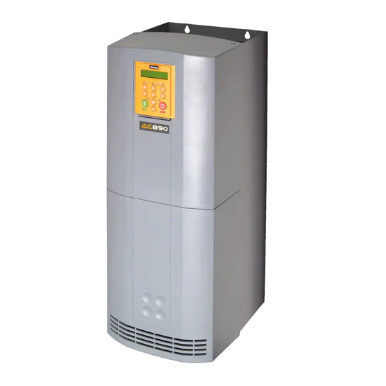
890SD (Standalone) Drives
Frames E & F with STO SIL3/PLe
HA501030U000 Issue 4
aerospace
climate control
electromechanical
filtration
fluid & gas handling
hydraulics
pneumatics
process control
sealing & shielding
ENGINEERING
YOUR
SUCCESS.
Advertisement
Table of Contents

Related Manuals for Parker 890SD


Summary of Contents for Parker 890SD
- Page 1 The full Product Manual is available on line at www.parker.com/ssd aerospace 890 QuickStart Manual climate control electromechanical filtration fluid & gas handling 890SD (Standalone) Drives hydraulics pneumatics Frames E & F with STO SIL3/PLe process control HA501030U000 Issue 4 sealing & shielding...
- Page 2 All rights strictly reserved. No part of this document may be stored in a retrieval system, or transmitted in any form or by any means to persons not employed by a Parker Hannifin Manufacturing Ltd., company without written permission from Parker Hannifin Manufacturing Ltd.
- Page 3 Page 2...
-
Page 4: Table Of Contents
Introduction ................................7 About this QuickStart Overview ................................8 Installation ................................9 Mounting Dimensions 890SD Frame E Power Connections ......................11 890SD Frame F Power Connections ......................12 890SD Control Connections ..........................13 890SD Feedback Connections ........................14 Drive Start-up ..............................15 Before Applying Power: Drive Set-up ................................ - Page 5 Page 4...
-
Page 6: Safety
The specifications, processes and circuitry described herein are for guidance only and may need to be adapted to the user's specific application. Parker Hannifin Manufacturing Limited does not guarantee the suitability of the equipment described in the Manual for individual applications. -
Page 7: Risk Assessment
Risk Assessment Under fault conditions, power loss or other operating conditions not intended, the equipment may not operate as specified. In particular: The motor speed may not be controlled The direction of rotation of the motor may not be controlled ... -
Page 8: Introduction
Introduction The 890SD Standalone Drive is designed for speed control of standard ac 3-phase motors. Control it remotely using configurable analogue and digital inputs and outputs. Control it locally using the 6901 Keypad. Use the Design System Explorer Configuration Tool (DSE 890) to give access to parameters, diagnostic messages, trip settings and application programming. -
Page 9: Overview
Overview Safe Torque Off Page 8... -
Page 10: Installation
Installation A simplified installation is shown below. This installation is not EMC compliant. For European installations and countries with EMC legislation refer to the 890 Engineering Reference Manual, Appendix C. 890SD 890SD X12/01 X12/01 X14/04 X14/04 Back-plate Cubicle Control Wiring... -
Page 11: Mounting Dimensions
Mounting Dimensions The units must be installed in a cubicle. Mount the drive using the keyholes and slots. Maximum Air Clearance Models Weight: Fixings kg/lbs 668.6 630.0 257.0 150.0 Use M6 Frame E 32.5/72 (26.3) (24.8) (10.1) (5.9) (12.3) (zero) (2.8) (2.8) fixings... -
Page 12: Sd Frame E Power Connections
890SD Frame E Power Connections Connect the 3-phase supply. Connect motor leads to M1/U, M2/V, M3/W. Maximum wire sizes: Maximum wire sizes:: Frame E: 50mm /1AWG (without crimp) Frame E: 50mm /1AWG (without crimp) 70mm / 1/0AWG (with crimp) -
Page 13: Sd Frame F Power Connections
890SD Frame F Power Connections Connect the 115 or 220Vac auxiliary Connect motor leads to M1/U, M2/V, M3/W. supply for the internal fans to AUX 1 and Maximum wire sizes:: AUX 2 (in any order). Frame F: 95mm / 4/0AWG (without crimp) -
Page 14: Sd Control Connections
890SD Control Connections Speed Reference Sequencing Analog Outputs Connect volt-free Connect a 10kΩ potentiometer at SPEED FEEDBACK contacts as required terminal block X12 (Analog I/P 3) 10V = ±100% speed at RUN (maintained contact) High (CW):... -
Page 15: Sd Feedback Connections
890SD Feedback Connections This section is only for closed loop vector and induction servo applications. Skip this page if there is no encoder or resolver mounted on the motor. Incremental Pulse Encoders OPTION F Terminal Block The default settings for the drive are for 2048 line,... -
Page 16: Drive Start-Up
Drive Start-up Before Applying Power: Read the Safety section at the front of the QuickStart. Ensure that all local electric codes are met. Check for damage to equipment. Check for loose ends, clippings, filings, drilling swarf etc. lodged in the drive and system. -
Page 17: Quick Setup Parameters
Quick Setup Parameters The following is a list of the Quick Setup parameters you must check before starting the drive. Set only the ones marked with “x” in the table below, under the intended mode of operation. V/Hz Vector Control Mode Select the intended operating mode Max Speed Motor RPM at full process speed... -
Page 18: Running In Local
Running in Local On the keypad select LOCAL mode. The display will show the Local Setpoint : 0.0% Use the UP arrow to set a Local Setpoint, say 20%. Press the green RUN button. The motor will accelerate to the desired speed and maintain it. Adjust RAMP ACCEL TIME in Quick Setup to the desired level. -
Page 19: Appendix A: Using The 6901 Keypad
Appendix A: Using the 6901 Keypad The 6901 keypad has a two-line backlit LCD display with units and symbols. It can be used to setup and configure the 890 in plain language. It can also be used to operate the drive in Local mode from its Start and Stop buttons, Jog and reverse. -
Page 20: The Menu Structure
The Menu Structure The main menus are shown below. Each menu contains parameters. This is the power-up welcome screen. If a different screen appears, press E a few times to return to this screen. OPERATOR Press the M key to get to the OPERATOR menu menu at level 1 DIAGNOSTICS DOWN arrow to get to the DIAGNOSTICS menu... -
Page 21: Appendix B: Analog And Digital I/O
Appendix B: Analog and Digital I/O The terminal function names apply to the factory shipping configuration. These terminals may have different functions if the configuration has been modified using DSE. Page 20... -
Page 22: Sd Control Terminals
890SD Control Terminals Page 21... - Page 23 Page 22...
-
Page 24: Appendix C: Electrical Ratings
Appendix C: Electrical Ratings Page 23... - Page 25 Page 24...
- Page 26 Page 25...
- Page 27 Page 26...
-
Page 28: Appendix D: Compliance
Appendix D: Compliance A comprehensive guide to product compliance is available in the full product manual. Warning Where there is a conflict between EMC and safety requirements personnel safety shall always take precedence. Operation of this equipment requires detailed installation and operation instructions provided in the installation/operation manual intended for use on this product. -
Page 29: Planning Cable Runs
Planning Cable Runs Use the shortest possible motor cable lengths. Use a single length of cable to a star junction point to feed multiple motors. Keep electrically noisy and sensitive cables apart. If this is not possible parallel cable runs should be separated by at least 0.25 meters, for runs longer than 10 meters, separation should be increased proportionally. - Page 30 (from AT, BE, CH, CZ, DE, EE, ES, FI, FR, IE, IL, IS, IT, LU, MT, NL, NO, PT, SE, SK, UK) © 2016 Parker Hannifin Corporation. All rights reserved. Parker Hannifin Manufacturing Limited, Automation Group, Electromechanical Drives Business Unit,...