
Related Manuals for Parker N2 NITROSource Compact N2C-2


Summary of Contents for Parker N2 NITROSource Compact N2C-2
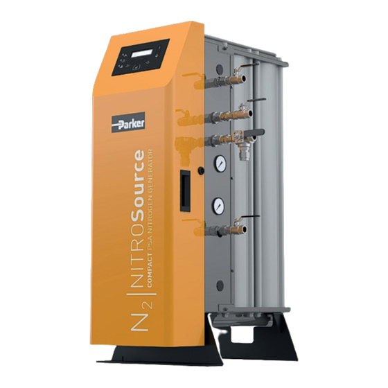
- Page 1 USER GUIDE: 17 651 1000 01/20 Rev - Preventative Maintenance Guide: 17 651 1100 NITROGEN GENERATOR NITROSource Compact N2C-2 / N2C-4 / N2C-6 / N2C-8 User Guide (EN)
-
Page 2: Table Of Contents
CONTENTS – Safety Information – Mechanical Installation – Electrical Installation – Markings and Symbols – Approvals – Receiving and Inspecting the Equipment – Generator Supply – Dryer Supply - Storage - Purge Economy - Remote Switching – Alarm Contacts – Unpacking –... - Page 3 CONTENTS – Changing Parameters – Insertion of Replacement Element – Oxygen Content – Replacement of Filter Head O-Ring - Economy Mode - Reconnecting the Filter Bowl with Head – Description – Cleaning – Service Intervals – Service Kits – Technical Specifi cation –...
- Page 4 SAFETY N2 Compact Nitrogen Gas Generator - User Guide. ©2020.
-
Page 5: Safety Information
If the user employs an operating procedure, item of equipment or a method of working which is not specifi cally recommended by Parker the user must ensure that the equipment will not be damaged or become hazardous to persons or property. -
Page 6: Markings And Symbols
MARKINGS AND SYMBOLS Th e following markings and international symbols are used on the equipment or within this user guide: Caution, Read the User Guide. Wear ear protection. Risk of electric shock. Pressurised components on the system. Highlights actions or procedures which, if not Remote control. -
Page 7: Receiving And Inspecting The Equipment
RECEIVING AND INSPECTING THE EQUIPMENT N2 Compact Nitrogen Gas Generator - User Guide. ©2020. -
Page 8: Unpacking
½ ” 3-Way Ball Valve If there are an signs of damage to the crate, or there are any parts missing please inform the delivery company immediately and contact your local Parker offi ce. STORAGE Th e equipment should be stored, within the packing crate, in a clean dry environment. If the crate is stored in an area where the environmental conditions fall outside of those specifi ed in the technical specifi cation, it should be moved to its fi nal location (installation site) and left to stabilise prior to unpacking. - Page 9 UNPACKING Remove the lid and all four sides of the packing crate (01) and unscrew the 4x transit bolts securing the generator to the base of the crate(02). Lift the generator from the pallet using suitable slings and an overhead crane (03). Carefully move the generator to its fi nal location, using a forklift truck or pallet truck, and refi t the silencer (04).
-
Page 10: Overview Of The Equipment
OVERVIEW OF THE EQUIPMENT N2 Compact Nitrogen Gas Generator - User Guide. ©2020. - Page 11 OVERVIEW OF THE EQUIPMENT DESCRIPTION DESCRIPTION User control interface O2 Analyser calibration port Column A pressure gauge N2 Outlet port to buff er (G½ ) Column B pressure gauge N2 inlet port from buff er vessel (G½ ) N2 Outlet pressure gauge N2 Outlet port (G½...
- Page 12 LOCATING THE EQUIPMENT N2 Compact Nitrogen Gas Generator - User Guide. ©2020.
-
Page 13: Environment
ENVIRONMENT Th e equipment should be located indoors in an environment that protects it from direct sunlight, moisture, and dust. Changes in temperature, humidity, and airborne pollution will aff ect the environment in which the equipment is operating and may impair the safety and operation. - Page 14 INSTALLATION COMMISSIONING N2 Compact Nitrogen Gas Generator - User Guide. ©2020.
-
Page 15: Recommended System Layout
Only competent personnel trained, qualifi ed, and approved by Parker should perform installation, commissioning, service and repair procedures. Warning RECOMMENDED SYSTEM LAYOUT DESCRIPTION DESCRIPTION DESCRIPTION DESCRIPTION Compressor Dryer pre-fi ltration AO Filter (supplied) Compact generator Wet air receiver Pre-treatment dryer... - Page 16 MECHANICAL INSTALLATION Fit one of the ½ ˝ball valves supplied to the compressed air inlet port on the generator and attach the compressed air supply to this ball valve. Ensure that the valve is in the closed position. Fit another of the ½ ˝ball valves supplied to the port marked “To Buff er vessel” . Install ½ ” NB / 16mm ID piping between the ball valve and the buff er vessel inlet port.
- Page 17 ELECTRICAL INSTALLATION A fully qualifi ed electrical engineer must undertake all fi eld wiring and electrical work in accordance with local regulations. Warning In order to maintain the IP rating of the generator, all cables entering the electrical enclosure must do so through the dedicated cable glands located on the side of the generator.
- Page 18 DRYER SUPPLY If a Parker pre-treatment air dryer is used, it should be connected to the generator at the dedicated DIN rail terminals. Refer to the documentation provided with your dryer for additional information on installation requirements.
- Page 19 ALARM CONTACTS Th e generator is fi tted with a set of volt free relay contacts designed for connection to a remote alarm circuit. Th e contacts are rated 1A max @ 250 Vac (1A @ 30Vdc). Under normal operation the relay is energised, when a fault occurs the relay will de-energise causing the relay contacts to change state.
- Page 20 OPERATING GENERATOR N2 Compact Nitrogen Gas Generator - User Guide. ©2020.
- Page 21 OVERVIEW OF THE CONTROLS O2 = 5.00% Shutting Down DESCRIPTION DESCRIPTION DESCRIPTION DESCRIPTION Operating status indicator Green = Running, Service / Fault indicator Start key Menu navigation keys Yellow = Starting up / Yellow = Service due Shutting down Red = Fault Red - Standby Economy / EST status indicator...
- Page 22 STARTING THE GENERATOR Inspect all of the system connection points and verify that they are secure. With both the inlet and outlet ball valves of the buff er vessel closed, open the ball valve on the air inlet port to allow the compressed air into the generator.
- Page 23 MENU INTERFACE All of the operational parameters and data are accessed through the menu driven interface. O2 = 5.00% O2 = 5.00% Shutting Down Shutting Down Hours economy Hours economy Service due at Service due at 8000h 8000h Hour meters Hour meters Hours Run Hours Run...
- Page 24 > 25% (% generators) / O > 1.05% (ppm generators Zero Drift Error Contact Parker Service Due Note. Any faults that are active when the power is switched off , and remain active when the power is re-applied, will cause a new entry to be added into the fault log.
- Page 25 CUSTOMER SETTINGS To prevent unauthorised access to the confi gurable parameters, the customers setting menu has optional password protection. Th is is disabled by default and can be enabled in menu 3.1 To gain access in to this menu, when password has been enabled: Press and hold both the keys for approximately 5 seconds until the menu changes to the password prompt as shown.
-
Page 26: Changing Parameters
If the generator is in economy shutdown when the pressure falls it will complete the cycle and then run through the a clean up cycle prior to going back online. Th e economy mode can be disabled within the customer settings menu, however Parker strongly recommend that this option remains enabled. - Page 27 SERVICING GENERATOR N2 Compact Nitrogen Gas Generator - User Guide. ©2020.
-
Page 28: Service Intervals
CLEANING Clean the equipment with a damp cloth only and avoid excessive moisture around any electrical sockets. If required you may use a mild detergent, however do not use abrasives or solvents as they may damage the warning labels on the equipment. SERVICE INTERVALS Description of Service Required Service Recommended Every:... -
Page 29: Service Kits
SERVICE KITS Recommended every 12 months Catalogue No's Description Contents Mist-X 150 silencer M12.N2C.0001 Kit: 12 month N2 Compact service P010AO element Recommended every 24 months Catalogue No's Description Contents M24.PPM.0002 Kit: 02 Cell PPM 02 Cell PPM M24.PCT.0002 Kit: 02 Cell % 02 Cell % Catalogue No's Description... -
Page 30: Exhaust Silencer Replacement
EXHAUST SILENCER REPLACEMENT Th e exhaust silencer is located under the inlet manifold assembly. Unscrew the element from the exhaust port (01) and discard (02). Fit the replacement element ensuring that it is fully engaged onto the pipe fi tting and secure it hand tight. OXYGEN CELL REPLACEMENT Unscrew the oxygen cell lead (01) and solenoid plugs (02) then remove the 4-20mA connections and move the lead to prevent obstruction. -
Page 31: Oxygen Analyser Calibration
Connect the O2 sample line between the elbow push in fi tting, located on the ball valve (3), and the O Analyser calibration port (1). If a sample line other than the one provided by Parker is used ensure that it is suitable rated for the working pressure of the generator. -
Page 32: Entering The Calibrated Level
ENTERING THE CALIBRATED LEVEL Navigate to menu 3.2 and press Using the keys enter the purity of the calibration gas. Press to send the calibration level to the O Analyser. On successful completion of the calibration the new O reading will be shown on the bottom line of the display. If the calibration is not successful the original reading from the analyser will be loaded. -
Page 33: Filter Depressurisation
FILTER DEPRESSURISATION Close the ball valves located on the inlet and outlet ports of the fi lter and depressurise it by opening the manual drain on the fi lter bowl (01). Caution 0 bar / 0 psi FILTER BOWL REMOVAL Unscrew the fi lter bowl (01 &... -
Page 34: Insertion Of Replacement Element
INSERTION OF REPLACEMENT OF FILTER REPLACEMENT ELEMENT HEAD O RING INTO FILTER BOWL Replace the O-ring located in the fi lter head with the new O-ring provided. Insert the new element into the fi lter bowl ensuring that the lugs are seated correctly in the grooves. Ensure to lubricate the O-ring and threads with a suitable acid free Petroleum jelly. -
Page 35: Technical Specification
TECHNICAL SPECIFICATION N2 Compact Nitrogen Gas Generator - User Guide. ©2020. - Page 36 DESCRIPTION Th e N Compact range of nitrogen generators operate on the Pressure Swing Adsorption (PSA) principle to produce a continuous stream of nitrogen gas from clean dry compressed air. Dual chamber columns, fi lled with extruded beads of adsorbent (Carbon Molecular Sieve [CMS]) material, are joined via an upper and lower manifold to produce a two bed system.
- Page 37 TECHNICAL SPECIFICATION UNITS 10PPM 100PPM 0.1% 0.5% Flowrate 0.81 1.54 2.48 3.69 4.39 6.11 7.73 9.13 10.29 N2C-2 1.73 2.94 4.96 7.58 9.12 12.95 15.89 18.38 20.57 N2C-4 10.8 12.1 2.41 4.46 7.59 11.06 13.32 18.64 22.68 26.06 29.04 N2C-6 11.0 13.3 15.3...
-
Page 38: Inlet Parameters
ENVIRONMENTAL INLET PARAMETERS PARAMETERS Inlet Air Quality ISO 8573-1:2001 Class 2.2.1 6 - 10 bar g 5 - 50 Inlet Pressure Ambient Temperature 87 - 145 psi g (41 - 122 5 - 50 Humidity 29% @ 50oC (80% max < 31 Inlet Temperature (41 - 122 IP Rating... -
Page 39: Generator Weights And Dimensions
GENERATOR WEIGHTS AND DIMENSIONS DIMENSIONS MM / (INS) Weight MODEL Kg / (lbs) 1040 406.5 681.5 753.5 868.5 207.5 237.5 N2C-2 (40.9) (18) (18.03) (14.76) (11.71) (16) (26.83) (29.66) (34.19) (8.17) (9.35) (216.1) 1040 466.5 406.5 681.5 753.5 868.5 207.5 237.5 N2C-4 (40.9) - Page 40 In the unlikely event that a problem occurs on the equipment, this troubleshooting guide can be used to identify the probable cause and remedy. Troubleshooting should only be attempted by competent personnel. All major repair and calibration work should be undertaken by a Parker trained, qualifi ed and approved engineer. Warning FAULT...
- Page 41 PARKER WORLDWIDE AE – UAE, FR – FRANCE, RO – ROMANIA, Dubai Contamine s/Arve Bucharest Tel: +971 4 8127100 Tel: +33 (0)4 50 25 80 25 Tel: +40 21 252 1382 parker.me@parker.com parker.france@parker.com parker.romania@parker.com AR – ARGENTINA, GR – GREECE, RU –...
- Page 42 PARKER HANNIFIN MANUFACTURING LIMITED Gas Separation and Filtration Division EMEA Dukesway, Team Valley Trading Est Gateshead, Tyne and Wear England NE11 0PZ Tel: +44 (0) 191 402 9000 Fax: +44 (0) 191 482 6296 www.parker.com/gsfe © Parker Hannifi n Corporation. All rights reserved.