Graco PR70 Instructions - Parts Manual
Feed system
Hide thumbs
Also See for PR70:
- Operation & maintenance manual (82 pages) ,
- Repair and parts manual (82 pages) ,
- Repair parts (72 pages)
Table of Contents
Advertisement
Quick Links
Instructions - Parts
™
PR70
Feed Systems
Fixed or variable ratio systems. For accurate metering, mixing, and dispensing of
two-component materials. For professional use only.
Not approved for use in European explosive atmosphere locations.
3000 psi (21 MPa, 207 bar) Maximum Working Pressure
100 psi (0.7 MPa, 7 bar) Maximum Air Inlet Pressure
Important Safety Instructions
Read all warnings and instructions in all sup-
plied manuals. Save these instructions.
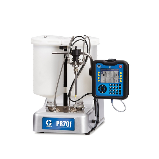
and PR70v
PR70v shown with Polyethylene Tanks and
Advanced Display Module
™
312394ZAC
EN
ti12580b
Advertisement
Table of Contents

Related Manuals for Graco PR70


Summary of Contents for Graco PR70
- Page 1 Instructions - Parts ™ ™ PR70 and PR70v Feed Systems 312394ZAC Fixed or variable ratio systems. For accurate metering, mixing, and dispensing of two-component materials. For professional use only. Not approved for use in European explosive atmosphere locations. 3000 psi (21 MPa, 207 bar) Maximum Working Pressure 100 psi (0.7 MPa, 7 bar) Maximum Air Inlet Pressure...
-
Page 2: Table Of Contents
Pressure Relief Procedure ....19 Graco Information ......74 Models with Advanced Display Module . -
Page 3: Product Configurator
PR7F - J - A5 - A5 - E - A6 - A6 - 3 - 1 - 2 - A - N - 3 - N - H - N - 6 - N - N Code: The following part number fields apply for the PR70 and PR70v part numbering configurator fields. Shaded items listed in the configurator table below are “Super Standard” items that are typically stocked and provide the best deliv- ery dates. - Page 4 Product Configurator 140, Available in Nylon Only Custom Low Volume side, consult fac- tory (stainless steel only) Code F Part Controls LC0272 Standard Display Module with 1 Fluid Control Module LC0274 Advanced Display Module with 1 Fluid Control Module LC0275 Advanced Display Module with 2 Fluid Control Modules Codes...
- Page 5 Product Configurator LC0163 Recirculating, On-Board Tanks, LC0191 Recirculating, Heated, On-Board 3/16 in. (4.8 mm) - 15 ft (4.6 m) Tanks, 1/4 in. (6.5 mm) - 10 ft (3.0 m) LC0164 Recirculating, On-Board Tanks, LC0192 Recirculating, Heated, On-Board 1/4 in. (6.5 mm) - 2.5 ft (0.6 m) Tanks, 1/4 in.
- Page 6 Product Configurator LC0406 High Pressure, 3/4 in. (19 mm) - 10 ft LC0474 High Pressure, Heated, 3/8 in. (9.5 (3.0 m) mm) - 15 ft (4.6 m) LC0407 High Pressure, 3/4 in. (19 mm) - 15 ft LC0475 High Pressure, Heated, 1/2 in. (13 (4.6 m) mm) - 2.5 ft (0.6 m) LC0432...
- Page 7 Product Configurator LC0314 One 2.0 gpm Flow Meter, One Code M Part Applicator Mounting 0.5 gpm Flow Meter, With Pressure LC0294 None, Customer Mount Controls and Transducers Applicator Code P Part High Volume Side Tank LC0292 Mast Mount, Controls & MD2 Applica- tor Machine Mounted None LC0293...
- Page 8 Product Configurator LC0126 8 L, Twin Polyethylene Tanks and LC0132 On-Board, Pneumatic Agitate, De-gas, Lids, Fill Port One 240V Agitator LC0142 Off-Board Pneumatic Agitator - 30 L LC0127 8 L, Twin Polyethylene Tanks and LC0143 Off-Board Pneumatic Agitator - 60 L Lids, LC0146 Off-Board Vacuum De-gas, Pneumatic...
- Page 9 Part Off-Board Tank Stands Agitator, Fill Port, Slinger - 30 L None LC0052 Off-Board Vacuum De-gas, Electric LC0103 PR70 Tank Stand Agitator, Fill Port, Slinger - 60 L LC0247 PR70v Tank Stand LC0130 On-Board, Pneumatic Agitate LC0131 On-Board, Pneumatic Agitate, De-gas...
-
Page 10: Warnings
Warnings Warnings The following warnings are for the setup, use, grounding, maintenance, and repair of this equipment. The exclama- tion point symbol alerts you to a general warning and the hazard symbol refers to procedure-specific risk. Refer back to these warnings. Additional, product-specific warnings may be found throughout the body of this manual where applicable. - Page 11 Warnings WARNING FIRE AND EXPLOSION HAZARD Flammable fumes, such as solvent and paint fumes, in work area can ignite or explode. To help prevent fire and explosion: • Use equipment only in well ventilated area. • Eliminate all ignition sources; such as pilot lights, cigarettes, portable electric lamps, and plastic drop cloths (potential static arc).
-
Page 12: Moisture Sensitivity Of Isocyanates
Never store ISO in an open container. • The PR70 has exposed shafts, so extra precautions must be taken when using ISO Materials. Make sure that the shafts are wiped clean and lubricated if sit- ting unused for any length of time, such as overnight shutdowns. -
Page 13: Grounding
Grounding Grounding Products that include electric agitators, heated hoses, or heated tanks must be grounded. In the event of an elec- trical short circuit, grounding reduces the risk of electric shock by providing an escape wire for the electric cur- rent. -
Page 14: Installation
Installation Installation Polyethylene Tank Lid with 7. Attach appropriate hoses and cables. Agitator • For electric agitator models, plug the agitator The polyethylene tank lid o-ring is installed with Kry- power cable into one of the outlets in the incom- tox. -
Page 15: Pneumatic Agitator Motor
Installation Pneumatic Agitator Motor Level Sensors Polyethylene Tanks Always maintain a minimum of one inch clearance between rotating agitator parts and container to pre- vent sparks caused by contact. 1. Install sensor (2001) using two screws (2003). The cable (2002) for the sensor should be pointing Air Line Lubricator towards the center of the machine base. - Page 16 Installation Stainless Steel Tanks Accumulators The accumulator level sensors (144) can be installed on any side of the main cylinder (123). However, the sensor must be the specified dis- tance from the pump flange. 2102 CAUTION To prevent machine damage, if the material being 2101 cycled through the accumulator is moisture sensitive, 2103...
-
Page 17: Auto-Refill Installation
Installation Auto-Refill Installation The Auto-Refill assembly is shipped uninstalled. The Auto-Refill assembly can be installed in multiple places on the tanks. See F . 5. ti12393a Possible locations for Auto-Refill installation. . 5: Auto-Refill Installation Locations Pressure Transducer and Flow Meter Installation See manual 312760. -
Page 18: Startup
Startup Startup 1. Locate power switch at rear of machine and turn power on. The display module will automatically turn on and begin to load. 2. Slide the system air pressure relief switch up. It is the yellow tab located at the rear, left of the machine. -
Page 19: Pressure Relief Procedure
Pressure Relief Procedure Pressure Relief Procedure Models with Advanced Display Models with Standard Display Module Module 1. Place a waste container below the dispense valve. With the machine in an idle state: 2. Navigate to the Manual screen. 1. If the machine pistons are not fully retracted, retract the pistons by pressing in the M1 screen. -
Page 20: Setup
Setup Setup Level Sensor Calibration Stainless Steel Tanks Polyethylene Tanks 2102 2001 2101 2103 ti12494a 2002 2104 Teach 2003 Element ti12493b 1. Empty tanks by executing multiple shots. 1. Locate the calibration button on the sensor (2101) closest to the electrical connector through one of the 2. -
Page 21: Vacuum De-Gas
Setup Vacuum De-gas 10. Close bottom ball valve of the vacuum tree manifold (1015). 11. Turn off the vacuum pump. 12. Open the top ball valve of the vacuum tree manifold (1015). This procedure is for assemblies with Vacuum Tree Manifold and No Agitator or Auto-Refill. -
Page 22: Vacuum De-Gas And Vacuum Auto-Fill
Setup Vacuum De-gas and Vacuum 12. If necessary, press the Abort/Cancel button ( Auto-Fill to cancel auto-refill. If an auto-refill is aborted or times out, the software This procedure is for assemblies with a Vacuum Tree Manifold, Agitator, and Auto-Refill. See F will not initiate a new auto-refill until a manually initi- on page 21 for part references. -
Page 23: Accumulator Filling
Accumulator air pressure should be set to the low- est possible setting to adequately run the accumu- lator. 8. See the PR70 and PR70v Operation manual refer- enced at the beginning of this manual to adjust dis- play module run settings for the accumulator. -
Page 24: Shutdown
Shutdown Shutdown If the machine is to remain idle for an extended period of time, perform the following steps. 1. Place a waste container below the dispense valve. 2. If installed, remove static mixer from the end of the dispense valve. 3. -
Page 25: Repair
Repair Repair Tank Removal 5. On models without ball valves, remove the tanks. • For polyethylene tank models, rotate the lock 1. On models without ball valves, empty tanks by ring (218) for each tank counter clockwise and executing multiple shots. lift the tanks off of the base. -
Page 26: Ball Valve Repair
Repair Stainless Steel Tanks 3. Reassemble and install the four screws that hold the ball valve assembly together. Follow ball valve removal from tank procedure in reverse order. NOTE: If adding or replacing a ball valve, use ball valve 506a kit 26A300. -
Page 27: Parts
Parts Parts Accumulators, Assemblies LC0160 and LC0297 Apply thread sealant tape to male npt threads prior to installation. Install the nut so it bottoms out on the thread. 111, 121 ti12449a 312394ZAC... - Page 28 Parts Accumulators, continued ti12472a Apply thread sealant tape to male npt threads prior to installation. 312394ZAC...
- Page 29 Part Description Part Description 95/0913/02 O-RING, ep, jbh 15T679 COVER, front, accumulator, (assembly LC0297 only) mild steel, PR70 95/0913/00 O-RING, fluoroelastomer, 01/1449/99 COVER, back, accumula- jbh (assembly LC0160 only) tor, mild steel 95/0605/01 SEAL, u-cup, 1/2 ID x 3/4 96/0282/98...
-
Page 30: Liter Polyethylene Tanks
Parts 8 Liter Polyethylene Tanks CAUTION The electric agitators used with on-board tanks will fail prematurely when material viscosity exceeds 24,000 cps. Use pneumatic agitators if material vis- cosity exceeds 24,000 cps. Assembly 255282 Shown ti12450a Apply thread sealant tape to male npt threads prior to installation. Do not attempt to remove from tank. - Page 31 Parts Quantity Part Description † O-RING, fluoroelastomer, bbc 95/0223/00 † O-RING 120902 SCREW, button head cap screw, M5 x 0.8 x 40 mm † SCREW, socket head cap, M5 x 0.8 x 18 mm 120904 120905 NUT, HEX, lock M5 X 0.8 120906 NUT, HEX, lock M8 X 1.25 120907...
-
Page 32: Polyethylene Tank Agitators
Parts Polyethylene Tank Agitators Electric Agitator Assemblies 255246 and 255503 Shown for reference only. Assembly 255246 Shown ti12456a 312394ZAC... - Page 33 Parts Part Description 01/2218/97 ENCLOSURE, agitator, electric, prmv/f, hd 01/2219/97 PLATE, adapter, electric agitator, hd, prm 81/2218-1/11 MOTOR, 50 rpm, 60 in-lb, 120V, 1.2A (assembly 255246 only) 256613 MOTOR, 50 rpm, 60 in-lb, 230V (assembly 255503 only) 81/1040/11 MODULE, ac, 2p, 250V, 10a, double pull sin- gle throw, w/fuse 81/1040-1/11 MODULE, ac connector, 2P, 250V, 10A, with...
- Page 34 Parts Pneumatic Agitator Assembly 255730 804, 811 Apply thread sealant tape to male npt threads prior to installation. Shown for reference only. ti12457a 312394ZAC...
- Page 35 Parts Part Description 82/0216/11 MOTOR, motor, pneumatic, agitator, 0.32 hp 94/0838/96 VALVE, needle, 1/8 npt x 1/8 npt, male / female 01/1189/98 ADAPTER, coupling, air motor, agitator 5-01-0510 SCREW, socket head cap, 10-32 x 5/8 in. 84/2215-A/11 COUPLING, alignment, 1 in. OD, hub, 3/8 in.
- Page 36 Parts Agitator Shaft, 255724 ti12458a Part Description 01/2230-1/98 PADDLE, agitator, tfm tank, stainless steel 01/2230-2/98 SUPPORT, mount, paddle, agitator 96/0097/98 FASTENER, screw, socket head cap, 10-24 x 1.25, stainless steel 96/0125/98 FASTENER, screw, socket head cap, 10-24 x 0.50, stainless steel 96/0129/98 WASHER, flat, SAE, #10, stainless steel, 1/2 in.
-
Page 37: On-Board Stainless Steel Tanks
Parts On-Board Stainless Steel Tanks Tank Assemblies LC0237, LC0238, LC0254, and LC0255 Right hand tank shown, left hand tank is mirror image. 304a Assembly LC0237 Shown ti12451a Use glass cloth tape to secure ground strap, thermal switch, and RTD to tank wall before adding heat blanket. Secure heat blanket to tank with string laced through eyelets. - Page 38 Parts Part Description Refer to Tanks for Use with Dust Covers and Tanks for Use with Clampdown Covers, page 44, for replacement or spare parts. LC0861 BLANKET, heat, 7.5L tank, 220V 256558 SWITCH, assy, thermal, 125C, 3P, M8 LC0056 BLANKET, insulation 304a LABEL, hot surface 121208...
- Page 39 Parts Tank Assemblies 255284, 255285, LC0235, LC0236, LC0012, and LC0013 It is recommended that the flat face of the tank faces the back of the base machine. Right hand tank shown, left hand tank is mirror image. 506a 506b 506c 506d ti12453a Assembly 255284 Shown...
-
Page 40: Ball Valve, Assembly 255280
Parts Ball Valve, Assembly 255280 2204a 2204b 2204c 2202 2201 2204h 2203 2204j 2205 2206 2204d 2204e ti12564a 2204f 2204g Part Description 2201 96/0075-1/99 WASHER, flat, sae, 7/16, mild steel, n series 2202 96/0075/99 WASHER, lock, split, 7/16, mild steel 2203 121012 SCREW, M8 x 1.25 65 mm, socket head cap screw, stainless steel... -
Page 41: Flange Assembly, 256896
Parts Flange Assembly, 256896 The flange assembly can be installed if no tanks or accumulators are installed. It allows for other feed sys- tem options to be installed onto the pump subassembly. 2701 ti12455a Part Description 2701 15M237 Flange, 1-1/2 in. npt 2702 * 95/0223/00 O-RING, fluoroelastomer, bbc 2703 * 120904 SCREW, socket head cap, M5... -
Page 42: On-Board Stainless Steel Tank Lids
Parts On-Board Stainless Steel Tank Lids Lid Assemblies LC0019 to LC0026 and LC0130 to LC0132 CAUTION The electric agitators used with on-board tanks will fail pre- maturely when material viscosity exceeds 24,000 cps. Use pneumatic agitators if material viscosity exceeds 24,000 cps. 1017 Assembly LC0025 Shown 1018... - Page 43 Parts Quantity Part Description 1005 --- Reference Only. Tank sold separately.‡ 1006 95/0518/00 O-RING, fluoroelastomer, JJF 1007 96/0282/98 FASTENER, screw, button head cap screw, 8-32 x 0.38, stainless steel 1008 96/0820/98 CLAMP, over the center, stainless steel 1009 96/0176-1/98 NUT, lock, 8-32, nylock, stainless steel 1010 15M320 LID, 7L, 2 npt, 1 9/16-32 15M321...
-
Page 44: Tanks For Use With Dust Covers
Parts Tanks for Use with Dust Covers LC0012 LC0235 LC0013 7.5 L stainless steel 7.5 L stainless steel 3 L stainless steel with high level port Tanks for Use with Clampdown Covers 24U714 24U713 24U715 7.5 L stainless steel 7.5 L stainless steel 3 L stainless steel with clamps with high level port... - Page 45 Parts Lid Assembly LC0018 1303 1301 1304 1302 ti12461a Apply thread sealant tape to male npt threads prior to installation. Part Description 1301 15M956 LID, mod, 7.5L & 3L, stainless steel 1302 96/0127/98 FASTENER, socket head cap screw, 1/4-20 x 0.37, stainless steel 1303 96/0148/11 KNOB, 1/4-20, female, plastic 1304 96/0311/98...
-
Page 46: Off-Board Stainless Steel Tanks
Parts Off-Board Stainless Steel Tanks Tank Assemblies Apply thread sealant tape to male npt threads prior to installation. ti12454a Assembly LC0054 Shown Part Description 111384 PLUG, pipe 103778 PLUG, pipe, headless 108832 O-RING 120904 SCREW, socket head cap, M5 x 0.8 x 18 mm 255391 SYSTEM, pipe and tube, 1-1/2 in. - Page 47 Parts Tank Assemblies ti12452a Use glass cloth tape to secure ground strap, thermal switch, and RTD to tank wall before adding heat blanket. Secure heat blanket to tank with string laced through eyelets. Insulation blanket should cover heat blanket completely. Secure insulation blanket to tank with 2 in.
- Page 48 Parts Pipe and Tube System, 255391 2806 Part Description 2808 TANK, assy, 30 L, stainless steel 2805 TANK, assembly, 60 L, stainless 2802 steel 2804 LC0257 BLANKET, assy, heat, 30L, 2801 240V, GCA LC0258 BLANKET, assy, heat, 60L, 240V, GCA 257757 INSULATOR, blanket assy, 38 L 257758...
-
Page 49: Off-Board Stainless Steel Tank Lids
Parts Off-Board Stainless Steel Tank Lids 1101 1103 1105 1102 1102 1101 1104 ti14656a Apply thread sealant tape to all pipe threads. Part Description 1101 111384 PLUG, pipe 1102 122767 BUSHING, 1/2 npt x 1/4 npt, stainless steel 1103 94/0736/96 VALVE, drain cock, 1/4 npt, male, brass 1104 --- LID, stainless steel 1105 15R145... - Page 50 Parts Lid Assembly Vacuum 1204 1202 1207 1203 1205 1206 1201 ti14722a 1202 Apply thread sealant tape to male npt threads prior to installation. Part Description 1201 187875 GAUGE, pressure, fluid 1202 122767 BUSHING, 1/2 npt x 1/4 npt, stainless steel 1203 15M861 FITTING, reducer, pipe, 3/4 x 1/4, stainless steel...
- Page 51 Parts 312394ZAC...
- Page 52 Parts Lid Assemblies Pneumatic Agitator CAUTION The electric agitators used with off-board tanks will fail prematurely when material viscosity exceeds 48,000 cps. Use pneumatic agitators if material vis- cosity exceeds 48,000 cps. 1401 Assembly LC0147 Shown 1406 1408 1403 1405 1407 1409 1404...
- Page 53 Parts Quantity 60 L, Pneumatic Pneumatic Pneumatic Agitator, Pneumatic Agitator, Agitator, Agitator, Vacuum Agitator, De-gas, De-gas, Fill De-gas, Fill Part Description De-gas De-gas 60 L Port, 30 L Port, 60 L 1401 24J183 AGITATOR 256822 MOTOR, single phase, 50/60 hz 1402 LID, agitator 1403...
- Page 54 Parts Lid Assemblies CAUTION The electric agitators used with off-board tanks will fail prematurely when material viscosity exceeds 48,000 cps. Use pneumatic agitators if material vis- cosity exceeds 48,000 cps. 1504 1503 1505 1501 1508 1507 1506 1506 1502 ti12464b Apply thread sealant tape to male npt threads prior to installation.
- Page 55 Parts Quantity 30 L Lid 60 L Lid Assembly Assembly 30 L Lid with with 30 L Lid Assembly Pneumatic Pneumatic Part Description Assembly with De-gas Agitator Agitator 1501 255607 BLADE, assy, agitator 255608 BLADE, assy, agitator 1502 1503 122776 RING, retaining, external, 0.750, mild steel ...
- Page 56 Parts Lid Assemblies Electric Agitator CAUTION The electric agitators used with off-board tanks will fail prematurely when material viscosity exceeds 48,000 cps. Use pneumatic agitators if material vis- cosity exceeds 48,000 cps. 1602 1608 1605 1606 1604 1609 1607 1603 1601 1611 1610...
- Page 57 Parts Quantity LID, assy, LID, assy, LID, assy, 7.5 gal, 15 gal, 7.5 gal, LID, assy, agit, vac, agit, vac, Part Description agit 15 gal, agit fill fill 1601 --- LID, agitator 1602 256822 MOTOR, assy, single phase, 50/60hz 1603 257608 BLADE, assy agitator, 75l 257607 BLADE, assy, agitator, 38l...
-
Page 58: Vacuum Tree Manifold, 255342
Parts Vacuum Tree Manifold, 255342 Vacuum Tree Manifold, 257746 3004 2901 3003 2902 2904 2905 3001 3002 2903 2902 ti12576a Part Description ti12575a 3001 1228444 FITTING, tee, 3/4 Apply thread sealant tape to male npt threads npt, male, 3k prior to installation. 3002 122770 VALVE, ball, 3/4 npt, female... - Page 59 Parts 312394ZAC...
-
Page 60: Stainless Steel Tank Agitators
Parts Stainless Steel Tank Agitators Electric Agitator Motor Assembly, 256822 1705 1707 1706 1701h 1701a 1701j 1701k 1701i 1701f 1701j 1701b 1701g 1701z 1701af 1701l 1701z 1701m 1701e, 1701t 1701n 1701v, 1701w, 1701r, 1701ab, 1701s 1701ac, 1701c, 1701ad, 1701o 1701d 1701ae, 1702, 1701p... - Page 61 Parts Part Description Part Description 1701 257605 HOUSING, agitator . 1701r 105510 WASHER, lock . 1701a 124741 MOTOR, agitator . 1701s 112222 SCREW, cap . 1701b 16K267 ADAPTER, plate, agitator . 1701t 100985 WASHER, lock motor . 1701u 15R328 JUNCTION BOX, motor .
- Page 62 Parts Electric Agitator Motor, Assemblies 255337 and 255338 2507 2508 2506 2511 2501 2513 2502 2509 2505 ti12584a 2503 2511 2504 2512 Assembly 255337 Shown Part Description 2501 01/1198-2/97 FASTENER, standoff, agitator, hd, elec, alu 2502 01/2218/97 ENCLOSURE, agitator, electric, prmv/f, hd 2504 01/2219/97 PLATE, adapter, electric agitator, hd, prm 2505 81/2218-1/11...
- Page 63 Parts Pneumatic Agitator Motor Assembly, 02/1116/50 2605 2604 2601 2602 2606 2603 ti12585a Part Description 2601 82/0216/11 MOTOR, pneumatic, agitator, 0.32 hp 2602 01/1189/98 ADAPTER, coupling, air motor, agitator 2603 01/1168/98 SHAFT, mount, pneumatic gear, agitator, stainless steel 2604 94/0838/96 VALVE, needle, 1/8 npt x 1/8 npt, male/female 2605 94/0702/96...
- Page 64 Parts Pneumatic Agitator Motor, 255670 Pneumatic Agitator Motor, 24J183 NOTE: This agitator assembly is no longer available. Piece parts from the assembly can be ordered but if the entire assembly is needed then agitator kit 24J182 must 2224 be ordered. 2211 2209 1801...
- Page 65 Parts Agitator Blade Assemblies 257607 and 257608 1902 1901 ti12468a Assembly 257607 Shown 1901c 1901b 1901b 1901a 1901c 1901d ti12474a Part Description 1901 257604 BLADE, assy, electric agitator 1901a 15Y362 BLOCK, blade, coupler, 1 in. diameter 1901b 15Y361 BLADE, agitator 1901c 551903 FASTENER, socket head cap screw,...
-
Page 66: Level Sensors
Parts Level Sensors Polyethylene Tanks Level Sensors, Assembly LC0278 2002 2001 ti12470b 2003 Part Description 2001 123549 SENSOR, level, quick disconnect 2002 121686 CABLE, M8 x M8, 4P, female / male, straight/right angle, 2 m 2003 96/1000/99 FASTENER, screw, socket head cap, M3 x 8, mild steel 312394ZAC... - Page 67 Parts Stainless Steel Tanks Level Sensors 2103 2102 2101 2104 ti12469a Reference Number, Description, Quantity 2101 2102 2103 2104 Sensor 121511 01/0025-EF/87 15U978 121684 121694 Package Description Level Sensor Level Sensor Well Sensor Well Cap CABLE, 2 m CABLE, 3 m Low level sensor for two 7.5 L tanks LC0279 Low level sensor for one 7.5 L tank...
-
Page 68: Kits
Mixer, 1/4 in. (6.5 mm) x 24 Luer Lock, the material tank. 250 Mixers ‡ Kit includes parts needed to add a ball valve to the PR70. MD2 Valve Kits See MD2 Dispense Valve instruction manual refer- enced at the beginning of this manual for installa- tion instructions or for more information. - Page 69 Kits Vacuum Kits Refill Kits These vacuum kits contain the parts necessary to attach Refill Kits 256659 and 256660 are designed to turn on a vacuum pump to the tanks. and off a transfer pump as needed to keep the tanks at the proper fluid level.
-
Page 70: Dimensions
Dimensions Dimensions Machine with On-Board Tanks ti12621b ti12622b PR70 † Assembly Dimensions, in. (mm) Polyethylene Tanks Stainless Steel Tanks 7.5 L, No 7.5 L, with No Agitators With Agitators Agitators Agitators 26.4 (670) 38.6 (980) 28.2 (716) 38.2 (970) 39.9 (1013) -
Page 71: Machine With Off-Board Tanks
Dimensions Machine with Off-Board Tanks ti12623c ti12624c PR70 † Assembly Dimensions, in. (mm) 30 L Tank 60 L Tank No Agitators With Agitators No Agitators With Agitators 55.7 (1415) 83.4 (2118) 64.9 (1648) 89.5 (2273) 32.1 (815) 32.1 (815) 32.1 (815) 32.1 (815) - Page 72 Dimensions 312394ZAC...
-
Page 73: Technical Data
Technical Data Technical Data Metering Pump Effective Area ..... 80 to 960 mm (0.124 to 1.49 in. ) per side Small Air Cylinder Effective Area . -
Page 74: Graco Standard Warranty
With the exception of any special, extended, or limited warranty published by Graco, Graco will, for a period of twelve months from the date of sale, repair or replace any part of the equipment determined by Graco to be defective.