Endress+Hauser RIA45 Operating Instructions Manual
Process indicator
Hide thumbs
Also See for RIA45:
- Operating instructions manual (80 pages) ,
- Brief operating instructions (44 pages) ,
- Brief operating instructions (20 pages)

Related Manuals for Endress+Hauser RIA45


Summary of Contents for Endress+Hauser RIA45
- Page 1 Products Solutions Services BA00272R/09/EN/07.22-00 71573625 2022-06-30 Valid from version 01.03.xx (device software) Operating Instructions RIA45 Process indicator...
-
Page 3: Table Of Contents
RIA45 Table of contents Table of contents About this document ....4 Maintenance ..... . 41 Symbols . -
Page 4: About This Document
About this document RIA45 About this document Symbols 1.1.1 Safety symbols DANGER This symbol alerts you to a dangerous situation. Failure to avoid this situation will result in serious or fatal injury. WARNING This symbol alerts you to a dangerous situation. Failure to avoid this situation can result in serious or fatal injury. -
Page 5: Documentation
RIA45 About this document Symbol Meaning Reference to graphic Notice or individual step to be observed … Series of steps Result of a step Help in the event of a problem Visual inspection 1.1.4 Symbols in graphics Symbol Meaning Symbol Meaning 1, 2, 3,... - Page 6 Technical Documentation supplied with the device are displayed. • Enter the serial number on the nameplate into the Endress+Hauser Operations app or scan the 2-D matrix code (QR code) on the nameplate with the Endress+Hauser Operations app: all data relating to the device and the Technical Documentation pertaining to the device is displayed.
-
Page 7: Safety Instructions
RIA45 Safety instructions Safety instructions Requirements for the personnel The personnel for installation, commissioning, diagnostics and maintenance must fulfill the following requirements: ‣ Trained, qualified specialists must have a relevant qualification for this specific function and task. ‣ Are authorized by the plant owner/operator. -
Page 8: Product Safety
Safety instructions RIA45 Product safety This product is designed in accordance with good engineering practice to meet state-of- the-art safety requirements and has been tested and left the factory in a condition in which it is safe to operate. Endress+Hauser... -
Page 9: Incoming Acceptance And Product
(www.endress.com/deviceviewer): all data relating to the device and an overview of the Technical Documentation supplied with the device are displayed. • Enter the serial number on the nameplate into the Endress+Hauser Operations App or scan the 2-D matrix code (QR code) on the nameplate with the Endress+Hauser Operations App: all the information about the device and the technical documentation pertaining to the device is displayed. -
Page 10: Storage And Transport
Incoming acceptance and product identification RIA45 3.3.1 Other standards and guidelines • IEC 60529: Degrees of protection provided by enclosures (IP code) • IEC 61010-1: Safety requirements for electrical equipment for measurement, control and laboratory • EN 60079-11: Explosive atmospheres - Part 11: Equipment protection by intrinsic safety "I" (optional) -
Page 11: Mounting
RIA45 Mounting Mounting Installation requirements NOTICE High temperatures reduce the life-time of the display. ‣ To avoid heat accumulation, ensure the device is sufficiently cooled. ‣ Do not operate the device in the upper temperature range over a longer period of time. -
Page 12: Post-Installation Check
Mounting RIA45 3. To secure the casing in the panel, hold the device level and push the mounting frame (item 2), with the threaded rods screwed in, over the casing until the frame locks into position (1). 4. Then tighten the threaded rods to fix the device in place (2.). -
Page 13: Wiring
RIA45 Wiring Wiring WARNING Danger! Electric voltage! ‣ The entire connection of the device must take place while the device is de-energized. ‣ The protective ground connection must be established before all other connections. If the protective ground is disconnected, this can be a source of danger. - Page 14 Wiring RIA45 5.1.1 Overview of possible connections on the process indicator Terminal assignment of analog inputs, channel 1 and 2 (optional) 15 16 17 18 25 26 27 28 A0010406 Loop power supply connection 2-wire 4-wire LPS 2-W LPS 4-W...
-
Page 15: Post-Connection Check
RIA45 Wiring Analog output connection Analog output 1 Analog output 2 (optional) O15 O16 O25O26 A0010416 A0010414 Digital output connection Digital output / open collector D11D12 A0010415 Power supply connection 24 to 230 V AC/DC (-20 % / +10 %) 50/60 Hz... -
Page 16: Operation
1. First install the device driver "CDI DTMlibrary" in FieldCare. It can be found in FieldCare under "Endress+Hauser Device DTMs → Service / Specific → CDI". 2. The DTM catalog in FieldCare must then be updated. Add the new installed DTMs to the DTM catalog. - Page 17 RIA45 Operation Installation of the Windows driver for TXU10/FXA291 Administrator rights are required to install the driver in Windows. Proceed as follows: 1. Connect the device to the PC using the TXU10/FXA291 interface adapter. A new device is detected and the Windows installation wizard opens.
-
Page 18: Display And Device Status Indicator / Led
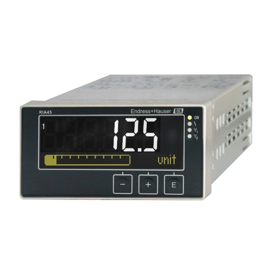
Operation RIA45 Display and device status indicator / LED The process indicator provides an illuminated LC display which is split into two sections. The segment section displays the value of the channel and additional information and alarms. In the dot matrix section, additional channel information, such as the TAG, unit or bar graph, is displayed in the display mode. -
Page 19: Quick Guide To The Operating Matrix
RIA45 Operation Underrange/overrange: The error and the channel identifier (TAG) are specified in the dot matrix section. 6.3.2 Icons in the editing mode The following characters are available for entering customized text: ‘0-9’, ‘a-z’, ‘A-Z’, ‘+’, ‘-’, ‘*’, ‘/’, ‘\’, ‘%’, ‘°’, ‘2’, ‘3’, ‘m’, ‘.’, ‘,’, ‘;’, ‘:’, ‘!’, ‘?’, ‘_’, ‘#’, ‘$’, ‘"’, ‘´’, ‘(’, ‘)’, ‘~’... - Page 20 Operation RIA45 Setup menu Description Application Application selection 1-channel 1-channel application 2-channel 2-channel application Diff-pressure Differential pressure application AI1 Lower range* Lower measuring range limit for Analog in 1 AI1 Upper range* Upper measuring range limit for Analog in 1 ...
- Page 21 RIA45 Operation Setup menu Description Calc value 2 Calculated value 2 See Calc value 1 Analog out 1 Analog output 1 Assignment Analog output assignment Signal type Signal type, analog output Lower range Lower range limit of analog output...
- Page 22 Operation RIA45 Expert menu Description Decimal places Decimal places for analog input Damping Damping Failure mode Failure mode Fixed fail value Fixed value in the event of an error (only if Failure mode = Fixed value) Namur NE43 Error limits according to Namur...
-
Page 23: Commissioning
RIA45 Commissioning Commissioning Post-installation check and switching on the device Make sure that all post-connection checks have been carried out before putting your device into operation: • Checklist for "post-installation check" → 12 • Checklist for "post-connection check" → 15 After the operating voltage is applied, the green LED lights up and the display indicates the device is ready for operation. -
Page 24: Device Configuration
Commissioning RIA45 9. Confirm the last position of the code in order to exit the menu. The full code is displayed. Press + to scroll back to the last item of the x Back submenu and confirm this item. By confirming the point, the value is adopted and the display returns to the Setup level. - Page 25 RIA45 Commissioning Differential pressure application A concise setup is available for differential pressure applications. Once the differential pressure application setup has been completed successfully, the difference between the two inputs is automatically calculated and the signal linearized using the configured parameters of the analog inputs and the linearization points. As a result, the volume is already shown on the display (= calculated value 2).
- Page 26 Commissioning RIA45 ‘Setup’ menu item Setup → Application → ‘Diff pressure’ Preconfigured by application package Submenu Setup analog inputs AI1 Lower range: start of measuring range, analog input 1 Signal: Current (corresponds to 4 mA for example) Range: 4-20 mA AI1 Upper range: end of measuring range, analog input 1 →...
- Page 27 RIA45 Commissioning Current Voltage RTD (resistance TC (thermocouple) Off (deactivate the temperature input) detector) Signal range Signal range (see Technical data); start and end of measuring range defined by the type selected Lower range Connection (RTD Start of measuring range; also enter the...
- Page 28 Commissioning RIA45 7.4.4 Step 4: Configuring the analog output(s) The device has one analog output (optionally two analog outputs). These outputs can be freely assigned to the inputs and channels available in the device. Setup Analog out 1 Analog out 2 Assignment: assignment of the output •...
- Page 29 RIA45 Commissioning Time base: Enter the time base in seconds. Only for the Gradient Time base for calculating the gradient operating mode. Hysteresis: The hysteresis is configured as an absolute value (only Hysteresis. For every set point, the switch point can be positive values) in the unit of the particular channel controlled via a hysteresis.
- Page 30 Commissioning RIA45 Measured value Setpoint Hysteresis Threshold “off” Setpoint “on” Setpoint “off” A0048461 6 Max operating mode Gradient The "Gradient" operating mode is used to monitor the change of the input signal over time. The alarm is triggered if the measured value reaches or exceeds the preset value. If the user configures a positive value, the limit value is monitored for increasing gradients.
- Page 31 RIA45 Commissioning Measured value Hysteresis Setpoint Setpoint Hysteresis Setpoint active Setpoint not active A0048463 8 OutBand operating mode InBand The limit value is violated as soon as the measured value to be checked exceeds or drops below a preset maximum or minimum respectively. The hysteresis must be monitored on the inside of the band.
- Page 32 Commissioning RIA45 Measured Delay Delay value Setpoint Hysteresis Delay time is reset Setpoint active Setpoint not active A0048465 10 Hysteresis and delay active 7.4.6 Step 6: Advanced device configuration (access protection/ operating code, saving the current setup) Access protection Access protection locks all the editable parameters, i.e.
- Page 33 RIA45 Commissioning 7.4.7 Step 7: Configuring the display functions The display is split into a 7-segment display section and a color section. The dot matrix section can be configured separately for each channel. Users can choose from all the active channels (analog inputs and calculated values).
- Page 34 Commissioning RIA45 In addition, the configured limit values for overfill protection must be secured against unintentional modification. The following function must be activated if additional access protection should be provided for the configuration software: Select Setup / Expert → System → Overfill protect: German WHG...
- Page 35 RIA45 Commissioning The damping is specified in seconds (can be configured in steps of 0.1 s , max. 999.9 s). Default values Input type Default value Current and voltage inputs 0.0 s Temperature inputs 1.0 s Once 5 times the filter time has elapsed, 99% of the actual measured value is reached.
-
Page 36: In Operation
Commissioning RIA45 Output → Relay 1/2 Time delay Sets the time delay for switching the relay Operating mode Operating mode of the relay. • norm opened • norm closed Failure mode • norm opened • norm closed NOTICE Setting the limit relay failure mode ‣... - Page 37 RIA45 Commissioning displayed appears in the color section of the display. The maximum and minimum value are provided for each active channel. Press the ‘+’ and ‘-’ simultaneously to exit a menu at any time. Any changes made are not saved.
- Page 38 Commissioning RIA45 Display Display - - - - - - - - - - Measured value - - - - - - - - - - - - - - - Points to note Status Range Under range Displayed and...
- Page 39 RIA45 Commissioning ‘Expert’ → ‘System’ → ‘Reset’ → ‘Factory reset’: reset all the parameters to the as- delivered state; all the configured parameters are overwritten. If a user code has been defined, it is overwritten!!! When operation is locked by a user code, this is indicated by a lock symbol on the display.
-
Page 40: Diagnostics And Troubleshooting
Diagnostics and troubleshooting RIA45 Diagnostics and troubleshooting To help you troubleshoot, the following section is designed to provide an overview of possible causes of errors. NOTICE Device malfunction possible when retrofitting with untested hardware ‣ When retrofitting the device with additional hardware (relay, additional universal input and additional analog output), the device software must perform an internal hardware test). -
Page 41: Maintenance
RIA45 Maintenance Error code Meaning Remedy C482 Info: simulation mode, relay/open collector For information purposes only. Device is working properly. C483 Info: simulation mode, analog output For information purposes only. Device is working properly. C561 Display overrun For information purposes only. Device is working properly. -
Page 42: Repair
Repair RIA45 Repair 10.1 General notes Repairs that are not described in these Operating Instructions must only be carried out directly by the manufacturer or by the service department. If ordering spare parts, specify the serial number of the device. Where necessary, installation instructions are supplied with the spare part. -
Page 43: Return
RIA45 Repair Item No. Designation 4-pin terminals for analog input Analog input terminal, non-Ex (terminals x1, x2, x3, x4 and x5, x6, x7, x8) Analog input terminal, Ex, blue, top (terminals x1, x2, x3, x4) Analog input terminal, Ex, blue, bottom (terminals x5, x6, x7, x8) -
Page 44: Accessories
Various accessories are available for the device, and can be ordered with the device or at a later stage from Endress+Hauser. Detailed information on the specific order code is available from your local Endress+Hauser sales organization or on the product page of the Endress+Hauser website: www.endress.com. -
Page 45: Technical Data
RIA45 Technical data Technical data 12.1 Input 12.1.1 Measured variable Current, voltage, resistance, resistance thermometer, thermocouples 12.1.2 Measuring ranges Current: • 0/4 to 20 mA +10% overrange • Short-circuit current: max. 150 mA • Load: 10 Ω Voltage: • 0 to 10 V, 2 to 10 V, 0 to 5 V, 0 to 1 V, 1 to 5 V, ±1 V, ±10 V, ±30 V, ±100 mV •... - Page 46 Technical data RIA45 Current/voltage output Current output: • 0/4 to 20 mA • Overrange up to 22 mA Voltage: • 0 to 10 V, 2 to 10 V, 0 to 5 V, 1 to 5 V • Overrange: up to 11 V, short-circuit proof, I <...
-
Page 47: Power Supply
RIA45 Technical data 12.3 Power supply 12.3.1 Terminal assignment LPS 4-W LPS 2-W 0/4...20mA 4...20mA 0/4...20mA U<=1V U>1V 25 26 27 28 0...10V 0/1...5V ±10V Typ J,K,T,N... ±100mV...±1V ±30V R12 R11 R13 R22 R21 R23 Analog Out 15 16 17 18 4...20mA... -
Page 48: Performance Characteristics
Technical data RIA45 Interface cable TXU10-AC PC USB interface • Connection: 4-pin socket • Transmission protocol: FieldCare • Order configuration: interface cable with FieldCare Device Setup DVD incl. all Comm DTMs and Device DTMs 12.4 Performance characteristics 12.4.1 Reference operating conditions... -
Page 49: Installation
RIA45 Technical data Accuracy Input: Range: Maximum measured error of measuring range (oMR): Typ T (Cu-CuNi), –270 to 400 °C (–454 to 752 °F) ± (0.10% oMR +0.5 K (0.9 °F)) (IEC60584) from –200 °C (–328 °F) Typ N (NiCrSi-NiSi), ±... -
Page 50: Environment
Technical data RIA45 Max. viewing angle range +/- 45° from the central display axis in every direction. 12.6 Environment 12.6.1 Ambient temperature NOTICE Operation in the upper temperature range reduces the operating life of the display. ‣ To avoid heat buildup, always ensure that the device is sufficiently cooled. -
Page 51: Mechanical Construction
RIA45 Technical data 12.7 Mechanical construction 12.7.1 Design, dimensions 118.6 (4.67) 16.7 96 (3.78) (0.66) 151.8 (5.98) 175 (6.89) A0010208 14 Dimensions of the panel meter in mm (in) Distance piece for terminals (Ex option) 12.7.2 Weight Approximately 300 g (10.6 oz) 12.7.3... -
Page 52: Operability
Technical data RIA45 12.8 Operability 12.8.1 Local operation A0010223 15 Display of the panel meter Channel display: 1: analog input 1; 2: analog input 2; 1M: calculated value 1; 2M: calculated value 2 Dot matrix display for TAG, bar graph and unit Limit value indicators in the bar graph "Operation locked"... -
Page 53: Accessories
Various accessories are available for the device, and can be ordered with the device or at a later stage from Endress+Hauser. Detailed information on the specific order code is available from your local Endress+Hauser sales organization or on the product page of the Endress+Hauser website: www.endress.com. -
Page 54: Appendix
Appendix RIA45 Appendix All the parameters available in the configuration menu are listed in the following tables. The values preconfigured at the factory are marked in bold. 13.1 Further explanations regarding the differential pressure application in level measurement Pressure sensors are connected at both universal inputs. The volume in the CV channels is ultimately calculated with the following calculation steps. - Page 55 RIA45 Appendix • 1 bar = 0.1 N/mm² = 10 N/m² = 10 • 1 mbar = 1 hPa = 100 Pa Conversion factors for various pressure engineering units Pascal Technical Physical Torr Pounds per atmosphere atmosphere square inch [Pa]...
-
Page 56: Display Menu
Appendix RIA45 Medium Density in [kg/m³] Carbon disulfide Diethyl ether 13.1.2 2nd calculation step: calculation of the volumetric content from the height The volume can be calculated using the linearization of the calculated height value. This is done by assigning a certain volume value to every height value, depending on the tank shape. -
Page 57: Setup Menu
RIA45 Appendix Calc value 1/2 Navigation Display → Calc value 1/Calc value 1 Description Configuration of the display for math 1 or math 2. If the parameter is set to ‘Off’, the channel is not displayed. Selection Unit Bar graph... - Page 58 Appendix RIA45 AI1/AI2 Lower range Navigation Setup → AI1 Lower range/AI2 Lower range Description Setting for the measuring range lower limit. User entry Numerical value Factory setting 0.0000 Additional information Only visible if Application → Diff pressure is configured.
- Page 59 RIA45 Appendix Factory setting 100.00 Additional information Only visible if Application → Diff pressure is configured. "Linearization" submenu Navigation Setup → Linearization Description Only visible if Application → Diff pressure is configured. No lin points Navigation Setup → Linearization → No lin points...
- Page 60 Appendix RIA45 Signal range Navigation Setup → Analog in 1/Analog in 2 → Signal range Description Setting for the input signal. The options that are available for selection depend on the "Signal type" that is set. Selection 4-20mA, 4-20mA squar, 0-20mA, 0-20mA squar...
- Page 61 RIA45 Appendix Unit Navigation Setup → Analog in 1/Analog in 2 → Unit Description Unit of the channel. User entry Customized text, max. 5 characters Additional information Only visible for "Signal type" = "Current" or "Voltage" Temperature unit Navigation ...
- Page 62 Appendix RIA45 Description Reset the saved min/max values. Selection Factory setting Submenu "Calc value 1"/"Calc value 2" Navigation Setup → Calc value 1/Calc value 2 Additional information Settings for Math 1 or Math 2 Calculation Navigation Setup → Calc value 1/Calc value 2 → Calculation Description Selection of calculation method.
- Page 63 RIA45 Appendix Description Setting for the 100% value for the bar graph User entry Numerical value Factory setting Factor Navigation Setup → Calc value 1/Calc value 2 → Factor Description Setting for the factor for the calculated value User entry...
- Page 64 Appendix RIA45 Description Reset the saved min/max values. Selection Factory setting Submenu "Analog Out 1"/"Analog Out 2" Navigation Setup → Analog Out 1/Analog Out 2 Additional information Settings for analog output 1 or analog output 2 Assignment Navigation Setup → Analog Out 1/Analog Out 2 → Assignment...
- Page 65 RIA45 Appendix Submenu "Relay 1"/"Relay 2" Navigation Setup → Relay 1/Relay 2 Additional information Settings for relay 1 or relay 2 Source Navigation Setup → Relay 1/Relay 2 → Source Description For selecting the source for the relay...
-
Page 66: Diagnostics Menu
Appendix RIA45 Description Time base for gradient evaluation in seconds. User entry 0-60 Factory setting Additional information Only visible if "Function" = "Gradient". Hysteresis Navigation Setup → Relay 1/Relay 2 → Hysteresis Description Hysteresis for switching threshold(s) User entry... - Page 67 RIA45 Appendix Navigation Diagnostics → Current diagn Description Displays the error code currently active Last diagn Navigation Diagnostics → Last diagn Description Displays the last error code Operating time Navigation Diagnostics → Operating time Description Displays the operating hours up until now Submenu "Diagnost logbook"...
-
Page 68: Expert Menu
Appendix RIA45 Order identifier Navigation Diagnostics → Device information → Order identifier Description Displays the order code Firmware version Navigation Diagnostics → Device information → Firmware version Description Displays the firmware version ENP version Navigation Diagnostics → Device information → ENP Version... - Page 69 RIA45 Appendix Submenu "Analog in 1"/"Analog in 2" Navigation Expert → Input → Analog in 1/Analog in 2 Description Settings for the analog inputs. Additional information The following parameters are available for analog input 1 and for analog input 2.
- Page 70 Appendix RIA45 Description Setting for the failure mode. Selection Invalid Fixed value Factory setting Invalid Additional information Invalid: An invalid value is output in the event of an error. Fixed value: A fixed value is output in the event of an error.
- Page 71 RIA45 Appendix Submenu "Output" Navigation Expert → Output Submenu "Analog Out 1"/"Analog Out 2" Navigation Expert → Output → Analog Out 1/Analog Out 2 Description Settings for the analog outputs. Additional information The following parameters are available for analog output 1 and analog output 2.
- Page 72 Appendix RIA45 Navigation Expert → Output → Relay 1/Relay 2 → Operating mode Description Normally closed = NC contact Normally opened = NO contact Selection Normally closed Normally opened Factory setting Normally closed Failure mode Navigation Expert → Output → Relay 1/Relay 2 → Failure mode...
- Page 73 RIA45 Appendix Navigation Expert → Application → Calc value 1/Calc value 2 → Fixed fail value Description The value set here is output in the event of an error. User entry Numerical value Factory setting Additional information Only visible if Failure mode = Fixed value.
- Page 74 Appendix RIA45 Simu relay 1/2 Navigation Expert → Simulation → Simu relay 1/Simu relay 2 Description Simulation of relay 1 or relay 2. Selection Closed Opened Factory setting 1) Numerical values consist of 6 digits, wherein the decimal point counts as a digit, e.g. +99.999...
-
Page 75: Index
RIA45 Index Index Access protection ......32 Measuring range limits ..... . . 37 Application conditions Min/Max memory . - Page 76 Index RIA45 No. lin points ......63 Submenu Offset ....... 61, 63 Analog in 1/2 .
- Page 80 *71573625* 71573625 www.addresses.endress.com...