Table of Contents
Advertisement
Quick Links
Advertisement
Table of Contents

Related Manuals for TCS IVW2221-015x


Summary of Contents for TCS IVW2221-015x
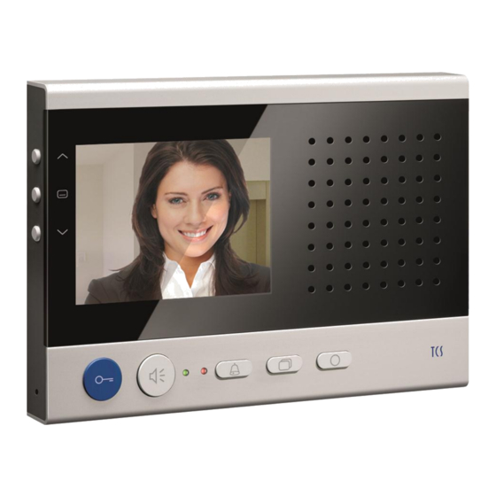
- Page 1 Product information ™ Video indoor station sky IVW2221-015x...
-
Page 2: Table Of Contents
Table of contents Scope of delivery ..................3 Safety instructions ................. 4 General safety regulations ..............4 Installation – protective measures ............4 Terms ....................... 4 Device overview ..................5 Indication and operating elements ............6 Intended use .................... 8 Short description .................. -
Page 3: Scope Of Delivery
Short messages ................... 27 Read short messages ............... 27 Delete short messages ..............28 Technical data ..................28 General to the conduit in TCS video systems ........29 6-wire operation ................... 29 Principle loop resistance ..............30 Measurement loop resistance ............30 Max. -
Page 4: Safety Instructions
When working in systems with 230 V mains voltage, the safety require- ments according to DIN VDE 0100 must be observed. When installing TCS:BUS systems, the general safety regulations for telecommunication systems according to VDE 0800 must be observed: separated cabling of heavy and low current lines, ... -
Page 5: Device Overview
Sub door call Call from a front-door station, with different buttons different ring tones can be generated at an indoor station. Thus the ring tone distinguished by the used serial number. The indoor station occupies an area of five serial numbers: Serial number SN (according to serial number sticker), SN+1, SN+2, SN+3, SN+4. -
Page 6: Indication And Operating Elements
Indication and operating elements Name Function display of the video image Screen indication of ring tone parameters and image parameters via OSD is ON: call OFF is activated Indication LED, flashes OFF: door release automatic or call diversion is activated ... - Page 7 Menu button Shortly press ** call main menu (in stand-by mode) select parameters for modification image (when parameter menu, ring tone parameter menu, time setting are activated) confirm the selection (if main, internal call or control function menu and short message indi- cation are activated) ...
-
Page 8: Intended Use
Navigation Press shortly reduce the value of the selected parameters (if button DOWN the image parameter menu or the ring tone pa- rameter menu is activated) one entry in the list down (if the internal call or control function menu is activated) ... -
Page 9: Short Description
Short description hands-free talking / manually controlled simplex communication can be activated blue door release button button for call acceptance resp. reversing key speak / listen, when simplex communication is activated 1 function key, ex works: allocated with control function / alternative alloca- tion can be activated: internal call, door release automatic, call diversion, light, call up control function menu or internal call menu / can be adjusted with configo™... -
Page 10: Mounting And Installation
Mounting and installation Installation height For an optimal viewing angle, we recommend an installation height of 1.60 m (top edge of the device). Notes Attention! The video indoor stations have to be installed and removed only voltage-free! When mounting the mounting plate on uneven ground, please do not over-tighten the screws as it can cause a deformation of the mounting plate. - Page 11 Setup the indoor station as end device Put the terminating resistor J1 on the two left contacts, if the device is in- (ex works) not plugged stalled at the end of a TCS:BUS vid- eo strand. plugged Install the adaptor plate Adaptor plate ...
-
Page 12: Connection Diagram
Install the device 4 lock bolt Remove the protective foil. Take the device into both hands. Put it on at the adaptor plate. Press the device flat onto the adaptor plate (1) and push the device careful- lock bolt ly vertical downwards (2), until the holes in the back of the device slide over the lock bolts. -
Page 13: Wiring Diagram
Wiring diagram Clip on the termi- nating resistor, if the device is installed at the end of a TCS:BUS video floor push strand. button floor push button 5-wire special operation If only 5 wires are available to connect the device, that the M-wire cannot be connected, it is possible to use the 5- wire special operation. -
Page 14: Commissioning
Commissioning First install the system completely, than connect it to voltage! V1 and V2 must not be connected to the P-, a- or b-wire. When connecting the video wires V1 (+) and V2 (-) the polarity is to be observed. -
Page 15: Configuration Options
blinking period of the green LED, if “video/speech channel is busy“ when pressing the speech button or press- ing the image button 3 x blinking internal stand-by time ca. 30 s floor door release time ca. 30 s timeout menu ring tone parameter 10 s timeout menu image parameter 10 s... -
Page 16: Programming The Function Key With The Service Device
cannot be shown as text in the display Programming the function key with the Service Device The indoor station is acting as a simplex communication device. The commands “9“ have to be used for configuring comfort simplex communi- cation devices (see product information Service Device). A programming with the commands “9“... -
Page 17: Symbols And Their Meaning
The live image is activated by pressing the image button or the speech button or when a door call is received. The OSD menu or the image buffer indication is switched off automatically after 10 s, if no button is pressed. Or: Press the function key to leave the menu. - Page 18 ring tone selection for sub ring menu for time setting of the tone 2 image buffer menu ring tone selection for sub ring main menu tone 3 ring tone selection for sub ring menu short messages tone 4 ...
-
Page 19: Help Function
Help function To simplify the operation of the device, symbols are faded-in in the upper right corner when calling the live image, the main menu and the sub menus. The symbols indicate, which button are available in the respective screen. The fade-in ends automatically after 5 s or at the first keystroke. -
Page 20: Enocean
pendently in front of the list entry, the latest switched status can be seen. Here, the two control function numbers as well as the serial number can be configured, whereby the device-individual serial number can be creat- ed, if required. enocean This function is realised identically to the IMM1100 to make sure that an enocean radio interface FBI4200 can be connected. -
Page 21: Send Internal Call
Send internal call Press the menu button. Select the symbol “Send internal call“. Select the required call destination with the navigation buttons UP or DOWN. Trigger a call by pressing the menu button. An acknowledgement tone sounds. The OSD is switched off (or switch-back to the live image). -
Page 22: Activate / Deactivate The Automatic Image Storage
Activate / deactivate the automatic image storage Activate Press the menu button longer than 4 s. An acknowledgement tone sounds. The main menu is faded-in for 3 s. The symbol image buffer changes its color from red to green. When receiving a door call, an image is stored automatically. -
Page 23: Delete A Stored Image
Delete a stored image To delete the shown image, press the naviga- tion button DOWN for 4 s, until an acknowl- edgement tone sounds. The image will be de- leted. The image stored before is shown. Delete all stored images In the external image buffer, all images allocated to the indoor station can be deleted completely. -
Page 24: Set Ring Tone Volume
Set ring tone volume Press the navigations button RIGHT (or LEFT), the symbol ring tone volume is pre-selected. Press the navigation button UP or DOWN, to regulate the volume. The level of the ring tone volume (1 to 4) is indicated in the display. While selecting the adjusted ring tone is reproducd in the selected volume and stored. -
Page 25: Setting Date And Time Of The Image Buffer
… when internal voice connection exists: After the sender of the internal call was displayed, the menu to set the internal conversation volume is indicated. Press the navigation button UP or DOWN to adjust the value. Setting date and time of the image buffer This dialog only appears, if the use of an external image buffer and the permission to set date and time has been released in the EEPROM. -
Page 26: Set Image Parameter
Set image parameter Symbols in the live image The symbols in the live image are faded- in for 10 s when image activation is ac- tive (after pressing the image button or after receiving a door call) or for 3 s after pressing the speech button. -
Page 27: Reload Factory Setting
Short messages The video indoor station IVW2221 can receive short messages via the TCS:BUS, store those and display them if required. Max. 10 short messages can be stored. The received message can include max. 95 characters. -
Page 28: Delete Short Messages
Select the required message with the navigation buttons UP or DOWN. Confirm the selection by pressing the menu button. You can read the message now. It in- cludes the message text as well as date and time it was sent. ... -
Page 29: General To The Conduit In Tcs Video Systems
1 Vss FBAS, floor input asymmetric 1 Vss FBAS Video 6-wire technique necessary! General to the conduit in TCS video systems 6-wire operation The 6-wire operation is the standard operation mode. Video operation, where two separated masses (b und M) are used. -
Page 30: Principle Loop Resistance
Table 1: Loop resistances Length of the line Line diameter a-b/ M-P in m 0.6 mm 0.8 mm Loop resistance in Ω 1.28 0.71 2.55 1.43 3.83 2.14 5.10 2.86 6.38 3.57 7.65 4.29 5.00 5.71 6.43 7.14 Principle loop resistance Measurement loop resistance ... -
Page 31: Max. Number Of Ivw2221 In 6-Wire Operation
Max. number of IVW2221 in 6-wire operation small /medium- max. num- sized systems ber IVW2221 VBVS05 larger max. num- AS front-door station system ber IVW2221 VS power supply and control unit IS Indoor station Note: The number of the front-door BVS20 + stations that can be connected is NGV1011... - Page 32 The colors of the The color intensity control Reduce the color intensity. video image are too of the video indoor station bright or the image is turned on too much in general is too The brightness control is Reduce the brightness. bright.
- Page 33 Please remove the second video cond image are visi- interfere. source from the line. ble. Connect the second video source, if necessary, via a video switch to the existing TCS:BUS. No image. Image No signal present. Connect the monitor in front of the...
-
Page 34: Cleaning
switch button does not video switch and check whether a respond by pressing. signal is available here. Measure the voltage between P and b. The voltage usually is about 24 V. If this is not the case; please check the BUS-power supply. Not both wires of the Please check the connection of video BUS are con-... -
Page 35: Warranty
We offer a simplified processing in case of warranty for electricians. Please note our conditions of sale and delivery, download from www.tcsag.de, Downloads, trade information and included in our current price list. Please contact the TCS HOTLINE. Spare parts Short text Article number... - Page 36 Hauptsitz TCS TürControlSysteme AG, TCS Hotline Deutschland: 0 4194/ 9 88 11 88 Geschwister-Scholl-Str. 7, 39307 Genthin Mail: hotline@tcsag.de Fon: 03933/879910, FAX: 03933/879911, Subject to technical changes Mail: info@tcs-germany.de, 08/2012 www.tcsag.de IWV2221-015x UK, Version 1A...