Table of Contents
Advertisement
Quick Links
Download this manual
See also:
User Manual
Advertisement
Table of Contents

Related Manuals for TCS IVX9001-0140


Summary of Contents for TCS IVX9001-0140
- Page 1 Product information Video indoor station IVX9001-0140...
-
Page 2: Table Of Contents
Switching lights and send control functions ........21 Automatic function................21 Setup Intercom ................. 22 General information on the conduit in TCS video systems ....23 6-wire operation .................. 23 Max. number of IVX9001-0140 in 6-wire operation ......24 Technical data ..................25 FAQ....................... -
Page 3: Scope Of Delivery
For working on systems with main connection of 230 V alternating volt- age, the safety requirements according to DIN VDE 0100 must be ob- served. When installing TCS:BUS systems, the general safety regulations for telecommunication systems according to VDE 0800 must be observed. Inter alia: ... -
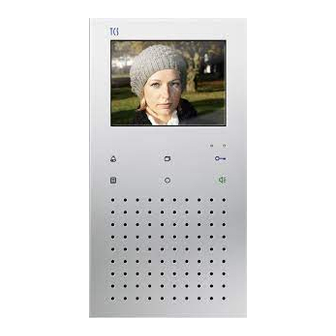
Page 4: Device Overview
Device overview Screen Sensor buttons Image button LED red LED green Call OFF Door release button button Menu button Speech button (sensor button) Function key Loudspeaker Microphone... -
Page 5: Indication And Operating Elements
change parameter in the OSD menu send control function 8 Function key for calling the central, if the IVX9001-0140 is configured for systems with central dwonwards in the OSD menu change parameter in the OSD menu ... -
Page 6: Intended Use
Intended use The video indoor station IVX9001-0140 is a video indoor station with color display for hands-free talking. The IVX9001-0140 is suitable for the operation in building communica- tion systems with combined audio / video systems. The operation is realised via the sensor buttons and the On-Screen- Display (OSD). -
Page 7: Mounting And Installation
Mounting and installation Install the lower cover Attention! The video indoor stations have to (de-)installed only volt- age-free! Ensure not to over-tighten the fastening screws when installing the lower cover on uneven ground. Over-tightened fastening screws can deform the lower cover. Thus, you may not be able to snap on the upper cover or the secure contacting between the lower and upper cover may be affected. -
Page 8: Set Indoor Station As End Device
Connect the lines Minimise the length of the lines above the lower cover to place the lines with- out any problems and to prevent clamping the lines when snapping-on the upper cover. Connect the lines according to the labeling within the lower cover to the connection terminal. -
Page 9: Open The Device
Open the device There is a release mechanism at the underside of the device. Slight- ly press into the opening with a screwdriver. Now the upper cover can be re- moved from the underside and separated from the lower cover. ... -
Page 10: Settings
Settings AS address-dependent image activation If there are also front-door stations without camera in combination with video front-door stations within one systems, the image is not activated if a call from such a front-door station comes in. To guarantee this function the possible AS addresses are separated into two areas: AS address reserved for video front-... -
Page 11: Configuration Options
Internal stand-by time if the indoor station is called 2 min if the indoor station is calling and 30 s waiting for call acceptance Floor door release time 35 s Timeout OSD 10 bis 120 s Timeout video image 10 bis 120 s Configuration options Function... -
Page 12: Settings Via Osd Menus
Settings via OSD menu Setup This level is permitted for the in- authorised persons only. Main menu staller 1 Internal call 2 Light and control Press the menu button (Operat- 3 Automatic function ing level in stand-by mode to open 4 Setup Intercom for the the main menu. - Page 13 Ring In the menu ring tone, the tone ring tones for door calls from Ring tone Door1 Tone: Alpha1 the front-door station (max. Door2 Tone: Alpha2 8), floor calls and internal Door3 Tone: Alpha2 Door4 Tone: Alpha2 calls can be set. Door5 Tone: Alpha1 ...
- Page 14 Parame- Image switch time: The screen switches OFF Parameter after the determined period Image switch time: 60 Length of call: of time (flat= 60 s). Parallel call SN: Length of call: Floor camera: deactivated The indoor station switches Floor door: permitted Call diversion: permitted OFF after the determined...
- Page 15 Enter the room and serial Internal call (des- Internal call number of the indoor station tinations) for internal calls. 01: Ro 10000 SN: 00000 02: Ro 0 SN: 0 Max. 10 internal calls can 02: Ro 0 SN: 0 02: Ro 0 SN: 0 be configured.
-
Page 16: Operation
Operation To accept a call In case of an incoming call Door call Speaking from a from a video front-door video station, the screen is au- front- tomatically activated and door sta- the video image is dis- tion played. ... - Page 17 Internal In case of an incoming call call from from another indoor sta- another tion, a ring tone sounds at indoor the indoor station. No vid- station eo image is displayed. Shortly press the speech button to speak to the person at the other indoor station.
-
Page 18: Sending A Call
Call from In case of an incoming call the cen- from the central, shortly tral press the speech button to speak to the person at the central. Shortly press the speech button to end the voice communication. Sending a call Call a Front door ... - Page 19 Press the menu button Send an Main menu internal 1 Internal call in stand-by mode to open 2 Light and control call the main menu. 3 Automatic function Press the image button 4 Setup Intercom or the function key to select the menu Internal call.
- Page 20 Video surveillance Video Front door Next Press the image button sur- veillance If several video front-door stations or cameras are connected, you can switch between these by pressing the image button again. Press the call-OFF button to switch OFF the im- age.
-
Page 21: Switching Lights And Send Control Functions
Switching lights and send control functions Press the menu button Light and control Main menu in stand-by mode to open 1 Internal call the main menu. 2 Light and control Press the image button 3 Automatic function or the function key 4 Setup Intercom select the menu Light and control. -
Page 22: Setup Intercom
Setup Intercom Press the menu button Setup user Setup Intercom in stand-by mode. (Opera- 1 Setup User 2 Setup Installer tion level Press the image button for the or the function key user) select the menu Setup In- tercom. -
Page 23: General Information On The Conduit In Tcs Video Systems
General information on the conduit in TCS video systems 6-wire operation The 6-wire operation is the standard operation mode. Video operation which is used with two separated earth connections (b and M). The conduit is determined by the structural conditions and is limited only by its length. -
Page 24: Max. Number Of Ivx9001-0140 In 6-Wire Operation
VS power supply and control unit, around 115 m distance AS-VS by 0.8 IS indoor station, FE extended function mm diameter Max. number of IVX9001-0140 in 6-wire operation max. num- small and me- ber of dium-sized IVX9001- systems... -
Page 25: Technical Data
Technical data supply voltage: +24 V ± 8 % (power supply and control unit) housing: plastics, white dimensions (in mm): H 180 mm x W 95 mm x D 19 mm weight: 240 g acceptable ambient temperature: 0 °C to 40 °C input current: I(a) = 0.4 mA, I(P) = 33 mA (stand-by) max. -
Page 26: Faq
Error pattern Possible causes Our suggested solution The video image is The color saturation Adjust the contrast or color satura- black and white. control of the indoor tion control. station is set to a mini- mum. The transmission level of At many components of the video the video BUS is too low. - Page 27 Please check if the number of allowable video indoor stations per line was not exceeded. The matching resistors Remove the terminating resistors are not inserted correctly at the relevant components. Only at the video distributors. the last video component in one strand needs a terminating resis- tor.
-
Page 28: Cleaning
Connect the second video source, if necessary, via a video switch to the existing TCS:BUS. No image. Image No signal present. Connect the monitor in front of the switch button does video switch and check whether a not respond when signal is available here. -
Page 29: Information On Disposal
Dispose the parts of the packaging in collecting tanks for card- board and paper resp. plastics. Warranty We offer a simplified processing in case of warranty for electricians. Please note our conditions of sale and delivery, for download from www.tcsag.de, Downloads, trade information. Please contact the TCS HOTLINE. -
Page 30: Service
Service Please send your questions and inquiries to hotline@tcsag.de Headquarters TCS TürControlSysteme AG, Subject to technical changes. Geschwister-Scholl-Str. 7, 39307 Genthin TCS Hotline Deutschland: Phone: +49 (0) 39 33/87 99 10 Phone: +49 (0) 4194/ 9 88 11 88 FAX: +49 (0) 39 33/87 99 11, FAX: +49 (0) 41 94/ 9 88 129 Mail: info@tcsag.de,...