Table of Contents
Advertisement
Quick Links
User's Guide
Publication Number 33250-90002 (order as 33250-90100 manual set)
Edition 2, March 2003
© Copyright Agilent Technologies, Inc. 2000, 2003
For Safety information, Warranties, and Regulatory information,
see the pages following the Index.
Agilent 33250A
80 MHz Function /
Arbitrary Waveform Generator
Advertisement
Table of Contents

Related Manuals for Agilent Technologies 33250A


Summary of Contents for Agilent Technologies 33250A
- Page 1 User’s Guide Publication Number 33250-90002 (order as 33250-90100 manual set) Edition 2, March 2003 © Copyright Agilent Technologies, Inc. 2000, 2003 For Safety information, Warranties, and Regulatory information, see the pages following the Index. Agilent 33250A 80 MHz Function /...
- Page 2 Agilent 33250A at a Glance The Agilent Technologies 33250A is a high-performance 80 MHz synthesized function generator with built-in arbitrary waveform and pulse capabilities. Its combination of bench-top and system features makes this function generator a versatile solution for your testing requirements now and in the future.
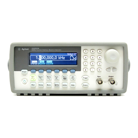
- Page 3 The Front Panel at a Glance 1 Graph Mode/Local Key 7 Utility Menu 2 Menu Operation Softkeys 8 Instrument Help Topic Menu 3 Waveform Selection Keys 9 Output Enable/Disable Key 4 Knob 10 Manual Trigger Key (used for 5 Modulation/Sweep/Burst Menus Sweep and Burst only) 6 State Storage Menu 11 Cursor Keys...
- Page 4 The Front-Panel Display at a Glance Menu Mode Mode Trigger Output Information Information Units Status Display Numeric Icon Readout Softkey Labels Graph Mode To enter the Graph Mode, press the key. Parameter Parameter Name Value Signal Ground The softkey colors correspond to the waveform parameters.
- Page 5 Front-Panel Number Entry You can enter numbers from the front-panel using one of two methods. Use the knob and arrow keys to modify the displayed number. Use the numeric keypad and menu softkeys to select the units.
- Page 6 The Rear Panel at a Glance 1 External 10 MHz Reference Input Terminal 5 Input: External Trig/FSK/Burst Gate 2 Internal 10 MHz Reference Output Terminal Output: Trigger Output 3 RS-232 Interface Connector 6 GPIB Interface Connector 4 External Modulation Input Terminal 7 Chassis Ground Use the menu to:...
- Page 7 Tutorial Chapter 7 discusses the fundamentals of signal generation and modulation techniques. Specifications Chapter 8 lists the function generator’s specifications. If you have questions relating to the operation of the Agilent 33250A, call 1-800-452-4844 in the United States, or contact your nearest Agilent Technologies Office.
-
Page 9: Table Of Contents
Contents Chapter 1 Quick Start To Prepare the Function Generator for Use 15 To Adjust the Carrying Handle 16 To Set the Output Frequency 17 To Set the Output Amplitude 18 To Set a DC Offset Voltage 20 To Set the Duty Cycle 21 To Configure a Pulse Waveform 22 To View a Waveform Graph 23 To Output a Stored Arbitrary Waveform 24... -
Page 10: Table Of Contents
Contents Chapter 4 Remote Interface Reference SCPI Command Summary 131 Simplified Programming Overview 142 Using the APPLy Command 144 Output Configuration Commands 153 Pulse Configuration Commands 166 Amplitude Modulation (AM) Commands 169 Frequency Modulation (FM) Commands 172 Frequency-Shift Keying (FSK) Commands 176 Frequency Sweep Commands 179 Burst Mode Commands 187 Triggering Commands 195... -
Page 11: Table Of Contents
Contents Chapter 7 Tutorial Direct Digital Synthesis 295 Creating Arbitrary Waveforms 298 Square Waveform Generation 300 Pulse Waveform Generation 300 Signal Imperfections 302 Output Amplitude Control 304 Ground Loops 305 Attributes of AC Signals 307 Modulation 309 Frequency Sweep 312 Burst 315 Chapter 8 Specifications Frequency Characteristics 320... - Page 13 Quick Start...
- Page 14 Quick Start One of the first things you will want to do with your function generator is to become acquainted with the front panel. We have written the exercises in this chapter to prepare the instrument for use and help you get familiar with some of its front-panel operations.
-
Page 15: To Prepare The Function Generator For Use
Then, verify that the function generator is turned on. If you need further assistance, refer to the Agilent 33250A Service Guide for instructions on returning the function generator to Agilent for service. -
Page 16: To Adjust The Carrying Handle
Chapter 1 Quick Start To Adjust the Carrying Handle To Adjust the Carrying Handle To adjust the position, grasp the handle by the sides and pull outward. Then, rotate the handle to the desired position. Bench-top viewing positions Carrying position... -
Page 17: To Set The Output Frequency
Chapter 1 Quick Start To Set the Output Frequency To Set the Output Frequency At power-on, the function generator outputs a sine wave at 1 kHz with an amplitude of 100 mV peak-to-peak (into a 50Ω termination). The following steps show you how to change the frequency to 1.2 MHz. 1 Press the “Freq”... -
Page 18: To Set The Output Amplitude
Chapter 1 Quick Start To Set the Output Amplitude To Set the Output Amplitude At power-on, the function generator outputs a sine wave with an amplitude of 100 mV peak-to-peak (into a 50Ω termination). The following steps show you how to change the amplitude to 50 mVrms. 1 Press the “Ampl”... - Page 19 Chapter 1 Quick Start To Set the Output Amplitude You can easily convert the displayed amplitude from one unit to another. For example, the following steps show you how to convert the amplitude from Vrms to Vpp. 4 Enter the numeric entry mode. Press the key to enter the numeric entry mode.
-
Page 20: To Set A Dc Offset Voltage
Chapter 1 Quick Start To Set a DC Offset Voltage To Set a DC Offset Voltage At power-on, the function generator outputs a sine wave with a dc offset of 0 volts (into a 50Ω termination). The following steps show you how to change the offset to –1.5 mVdc. -
Page 21: To Set The Duty Cycle
Chapter 1 Quick Start To Set the Duty Cycle To Set the Duty Cycle Applies only to square waves. At power-on, the duty cycle for square waves is 50%. You can adjust the duty cycle from 20% to 80% for output frequencies up to 25 MHz. -
Page 22: To Configure A Pulse Waveform
Chapter 1 Quick Start To Configure a Pulse Waveform To Configure a Pulse Waveform You can configure the function generator to output a pulse waveform with variable pulse width and edge time. The following steps show you how to configure a 500 ms pulse waveform with a pulse width of 10 ms and edge times of 50 µs. -
Page 23: To View A Waveform Graph
Chapter 1 Quick Start To View a Waveform Graph To View a Waveform Graph In the Graph Mode, you can view a graphical representation of the current waveform parameters. Each softkey parameter is shown in a different color corresponding to the lines above the softkeys at the bottom of the display. -
Page 24: To Output A Stored Arbitrary Waveform
Chapter 1 Quick Start To Output a Stored Arbitrary Waveform To Output a Stored Arbitrary Waveform There are five built-in arbitrary waveforms stored in non-volatile memory. The following steps show you how to output the built-in “exponential fall” waveform from the front panel. For information on creating a custom arbitrary waveform, refer to “To Create and Store an Arbitrary Waveform”... -
Page 25: To Use The Built-In Help System
Chapter 1 Quick Start To Use the Built-In Help System To Use the Built-In Help System The built-in help system is designed to provide context-sensitive assistance on any front-panel key or menu softkey. A list of help topics is also available to assist you with several front-panel operations. 1 View the help information for a function key. - Page 26 Chapter 1 Quick Start To Use the Built-In Help System 3 View the list of help topics. Press the key to view the list of available help topics. To scroll through the list, press the ↑ or ↓ softkey or rotate the knob. Select the third topic “Get HELP on any key”...
-
Page 27: To Rack Mount The Function Generator
To Rack Mount the Function Generator To Rack Mount the Function Generator You can mount the Agilent 33250A in a standard 19-inch rack cabinet using one of two optional kits available. Instructions and mounting hardware are included with each rack-mounting kit. Any Agilent System II instrument of the same size can be rack-mounted beside the Agilent 33250A. - Page 28 Chapter 1 Quick Start To Rack Mount the Function Generator To rack mount a single instrument, order adapter kit 5063-9240. To rack mount two instruments side-by-side, order lock-link kit 5061-9694 and flange kit 5063-9212. Be sure to use the support rails in the rack cabinet. In order to prevent overheating, do not block the flow of air into or out of the instrument.
- Page 29 Front-Panel Menu Operation...
- Page 30 Front-Panel Menu Operation This chapter introduces you to the front-panel keys and menu operation. This chapter does not give a detailed description of every front-panel key or menu operation. It does, however, give you an overview of the front- panel menus and many front-panel operations. See chapter 3 “Features and Functions,”...
-
Page 31: Front-Panel Menu Reference
Chapter 2 Front-Panel Menu Operation Front-Panel Menu Reference Front-Panel Menu Reference This section gives an overview of the front-panel menus. The remainder of this chapter contains examples of using the front-panel menus. Configure the modulation parameters for AM, FM, and FSK. •... - Page 32 Chapter 2 Front-Panel Menu Operation Front-Panel Menu Reference Store and recall instrument states. • Store up to four instrument states in non-volatile memory. • Assign a custom name to each storage location. • Recall stored instrument states. • Restore all instrument settings to their factory default values. •...
-
Page 33: To Select The Output Termination
To Select the Output Termination To Select the Output Termination The Agilent 33250A has a fixed series output impedance of 50 ohms to the front-panel Output connector. If the actual load impedance is different than the value specified, the displayed amplitude and offset levels will be incorrect. -
Page 34: To Output A Modulated Waveform
Chapter 2 Front-Panel Menu Operation To Output a Modulated Waveform To Output a Modulated Waveform A modulated waveform consists of a carrier and a modulating waveform. In AM (amplitude modulation), the amplitude of the carrier is varied by the amplitude of the modulating waveform. For this example, you will output an AM waveform with 80% modulation depth. - Page 35 Chapter 2 Front-Panel Menu Operation To Output a Modulated Waveform 4 Set the modulating frequency. Press the AM Freq softkey and then set the value to 200 Hz using the numeric keypad or the knob and arrow keys. 5 Select the modulating waveform shape. Press the Shape softkey to select the shape of the modulating waveform.
-
Page 36: To Output An Fsk Waveform
Chapter 2 Front-Panel Menu Operation To Output an FSK Waveform To Output an FSK Waveform You can configure the function generator to “shift” its output frequency between two preset values using FSK modulation. The rate at which the output shifts between the two frequencies (called the “carrier frequency” and the “hop frequency”) is determined by the internal rate generator or the signal level on the rear-panel Trig In connector. - Page 37 Chapter 2 Front-Panel Menu Operation To Output an FSK Waveform 3 Set the “hop” frequency. Press the Hop Freq softkey and then set the value to 500 Hz using the numeric keypad or the knob and arrow keys. 4 Set the FSK “shift” rate. Press the FSK Rate softkey and then set the value to 100 Hz using the numeric keypad or the knob and arrow keys.
-
Page 38: To Output A Frequency Sweep
Chapter 2 Front-Panel Menu Operation To Output a Frequency Sweep To Output a Frequency Sweep In the frequency sweep mode, the function generator “steps” from the start frequency to the stop frequency at a sweep rate which you specify. You can sweep up or down in frequency, and with either linear or logarithmic spacing. - Page 39 Chapter 2 Front-Panel Menu Operation To Output a Frequency Sweep 4 Set the stop frequency. Press the Stop softkey and then set the value to 5 kHz using the numeric keypad or the knob and arrow keys. At this point, the function generator outputs a continuous sweep from 50 Hz to 5 kHz (if the output is enabled).
-
Page 40: To Output A Burst Waveform
Chapter 2 Front-Panel Menu Operation To Output a Burst Waveform To Output a Burst Waveform You can configure the function generator to output a waveform with a specified number of cycles, called a burst. You can output the burst at a rate determined by the internal rate generator or the signal level on the rear-panel Trig In connector. - Page 41 Chapter 2 Front-Panel Menu Operation To Output a Burst Waveform 3 Set the burst count. Press the #Cycles softkey and then set the count to “3” using the numeric keypad or knob. 4 Set the burst period. Press the Burst Period softkey and then set the period to 20 ms using the numeric keypad or the knob and arrow keys.
-
Page 42: To Trigger A Sweep Or Burst
Chapter 2 Front-Panel Menu Operation To Trigger a Sweep or Burst To Trigger a Sweep or Burst You can issue triggers from the front panel for sweeps and bursts using a manual trigger or an internal trigger. • Internal or “automatic” triggering is enabled with the default settings of the function generator. -
Page 43: To Store The Instrument State
Chapter 2 Front-Panel Menu Operation To Store the Instrument State To Store the Instrument State You can store the instrument state in one of four non-volatile storage locations. A fifth storage location automatically holds the power-down configuration of the instrument. When power is restored, the instrument can automatically return to its state before power-down. -
Page 44: To Configure The Remote Interface
Chapter 2 Front-Panel Menu Operation To Configure the Remote Interface To Configure the Remote Interface The instrument is shipped with both a GPIB (IEEE-488) interface and an RS-232 interface. Only one interface can be enabled at a time. The GPIB interface is selected when the instrument is shipped from the factory. - Page 45 Chapter 2 Front-Panel Menu Operation To Configure the Remote Interface RS-232 Configuration 1 Select the RS-232 interface. Press and then select the RS-232 softkey from the “I/O” menu. 2 Set the baud rate. Press the Baud Rate softkey and select one of the following: 300, 600, 1200, 2400, 4800, 9600, 19200, 38400, 57600 (factory setting), or 115200 baud.
- Page 47 Features and Functions...
- Page 48 Features and Functions You will find that this chapter makes it easy to look up all the details about a particular feature of the function generator. Whether you are operating the function generator from the front panel or over the remote interface, this chapter will be useful.
-
Page 49: Output Configuration
Chapter 3 Features and Functions Output Configuration Output Configuration This section contains information to help you configure the function generator for outputting waveforms. You may never have to change some of the parameters discussed here, but they are provided to give you the flexibility you might need. - Page 50 Chapter 3 Features and Functions Output Configuration • Function Limitations: If you change to a function whose maximum frequency is less than that of the current function, the frequency is adjusted to the maximum value for the new function. For example, if you are currently outputting an 80 MHz sine wave and then change to the ramp function, the function generator will automatically adjust the output frequency to 1 MHz (the upper limit for ramps).
- Page 51 Chapter 3 Features and Functions Output Configuration Output Frequency As shown below, the output frequency range depends on the function currently selected. The default frequency is 1 kHz for all functions. Function Minimum Frequency Maximum Frequency 1 µHz Sine 80 MHz 1 µHz Square 80 MHz...
- Page 52 Chapter 3 Features and Functions Output Configuration • Front-Panel Operation: To set the output frequency, press the Freq softkey for the selected function. Then use the knob or numeric keypad to enter the desired frequency. To set the waveform period instead, press the Freq softkey again to toggle to the Period softkey.
- Page 53 Chapter 3 Features and Functions Output Configuration • You can set the output amplitude in Vpp, Vrms, or dBm. For more information, see “Output Units” on page 56. • You cannot specify the output amplitude in dBm if the output termination is currently set to “high impedance”.
- Page 54 Chapter 3 Features and Functions Output Configuration • Remote Interface Operation: VOLTage {<amplitude>|MINimum|MAXimum} Or, you can set the amplitude by specifying a high level and low level using the following commands. VOLTage:HIGH {<voltage>|MINimum|MAXimum} VOLTage:LOW {<voltage>|MINimum|MAXimum} You can also use the APPLy command to select the function, frequency, amplitude, and offset with a single command.
- Page 55 Chapter 3 Features and Functions Output Configuration • Arbitrary Waveform Limitations: For arbitrary waveforms, the maximum offset and amplitude will be limited if the waveform data points do not span the full range of the output DAC (Digital-to-Analog Converter). For example, the built-in “Sinc” waveform does not use the full range of values between ±1 and therefore its maximum offset is limited to 4.95 volts (into 50 ohms).
- Page 56 Chapter 3 Features and Functions Output Configuration Output Units Applies to output amplitude only. At power-on, the units for output amplitude are volts peak-to-peak. • Output units: Vpp, Vrms, or dBm. The default is Vpp. • The unit setting is stored in volatile memory; the units are set to “Vpp”...
- Page 57 Chapter 3 Features and Functions Output Configuration Output Termination Applies to output amplitude and offset voltage only. The Agilent 33250A has a fixed series output impedance of 50 ohms to the front-panel Output connector. If the actual load impedance is different than the value specified, the displayed amplitude and offset levels will be incorrect.
- Page 58 Chapter 3 Features and Functions Output Configuration Duty Cycle Applies to square waves only. Duty cycle represents the amount of time per cycle that the square wave is at a high level (assuming that the waveform polarity is not reversed). 20% Duty Cycle 80% Duty Cycle •...
- Page 59 Chapter 3 Features and Functions Output Configuration Symmetry Applies to ramp waves only. Symmetry represents the amount of time per cycle that the ramp wave is rising (assuming that the waveform polarity is not reversed). 0% Symmetry 100% Symmetry • The symmetry is stored in volatile memory; the symmetry is set to 100% when power has been off or after a remote interface reset.
- Page 60 Chapter 3 Features and Functions Output Configuration Voltage Autoranging In the default mode, autoranging is enabled and the function generator automatically selects the optimal settings for the output amplifier and attenuators. With autoranging disabled, the function generator uses the current amplifier and attenuator settings. •...
- Page 61 Chapter 3 Features and Functions Output Configuration Waveform Polarity In the normal mode (default), the waveform goes positive during the first part of the cycle. In the inverted mode, the waveform goes negative during the first part of the cycle. •...
- Page 62 Chapter 3 Features and Functions Output Configuration Sync Output Signal A sync output is provided on the front-panel Sync connector. All of the standard output functions (except dc and noise) have an associated Sync signal. For certain applications where you may not want to output the Sync signal, you can disable the Sync connector.
- Page 63 Chapter 3 Features and Functions Output Configuration • For FSK, the Sync signal is referenced to the “hop” frequency and is a square waveform with a 50% duty cycle. The Sync signal is a TTL “high” on the transition to the “hop” frequency. •...
-
Page 64: Pulse Waveforms
Chapter 3 Features and Functions Pulse Waveforms Pulse Waveforms A shown below, a pulse waveform consists of a period, a pulse width, a rising edge, and a falling edge. Pulse Width Rise Time Fall Time Period Pulse Period • Pulse period: 20 ns to 2000 seconds. The default is 1 ms. •... - Page 65 Chapter 3 Features and Functions Pulse Waveforms • Front-Panel Operation: After selecting the pulse function, press the Freq softkey again to toggle to the Period softkey. Then use the knob or numeric keypad to enter the desired pulse period. • Remote Interface Operation: PULSe:PERiod {<seconds>|MINimum|MAXimum} Pulse Width The pulse width represents the time from the 50% threshold of the...
- Page 66 Chapter 3 Features and Functions Pulse Waveforms Edge Time The edge time represents the time from the 10% threshold to the 90% threshold of both the rising and falling edges. • Edge time: 5 ns to 1 ms (see restrictions below). The default edge time is 5 ns.
-
Page 67: Amplitude Modulation (Am)
Chapter 3 Features and Functions Amplitude Modulation (AM) Amplitude Modulation (AM) A modulated waveform consists of a carrier waveform and a modulating waveform. In AM, the amplitude of the carrier is varied by the instantaneous voltage of the modulating waveform. The function generator will accept an internal or external modulation source. - Page 68 Chapter 3 Features and Functions Amplitude Modulation (AM) Carrier Waveform Shape • AM carrier shape: Sine, Square, Ramp, or Arbitrary waveform. The default is Sine. You cannot use pulse, noise, or dc as the carrier waveform. • Front-Panel Operation: Press any of the front-panel function keys except .
- Page 69 Chapter 3 Features and Functions Amplitude Modulation (AM) Modulating Waveform Shape The function generator will accept an internal or external modulation source for AM. • Modulating waveform shape (internal source): Sine, Square, Ramp, Negative Ramp, Triangle, Noise, or Arb waveform. The default is Sine. •...
- Page 70 Chapter 3 Features and Functions Amplitude Modulation (AM) Modulation Depth The modulation depth is expressed as a percentage and represents the extent of the amplitude variation. At 0% depth, the output amplitude is half of the selected value. At 100% depth, the output amplitude equals the selected value.
- Page 71 Chapter 3 Features and Functions Amplitude Modulation (AM) Modulating Source The function generator will accept an internal or external modulation source for AM. • Modulating source: Internal or External. The default is Internal. • If you select the External source, the carrier waveform is modulated with an external waveform.
-
Page 72: Frequency Modulation (Fm)
Chapter 3 Features and Functions Frequency Modulation (FM) Frequency Modulation (FM) A modulated waveform consists of a carrier waveform and a modulating waveform. In FM, the frequency of the carrier is varied by the instantaneous voltage of the modulating waveform. For more information on the fundamentals of Frequency Modulation, refer to chapter 7, “Tutorial”. - Page 73 Chapter 3 Features and Functions Frequency Modulation (FM) Carrier Waveform Shape • FM carrier shape: Sine, Square, Ramp, or Arbitrary waveform. The default is Sine. You cannot use pulse, noise, or dc as the carrier waveform. • Front-Panel Operation: Press any of the front-panel function keys except .
- Page 74 Chapter 3 Features and Functions Frequency Modulation (FM) Carrier Frequency The maximum carrier frequency depends on the function selected as shown below. The default is 1 kHz for all functions. Function Minimum Frequency Maximum Frequency Sine 5 Hz 80 MHz Square 5 Hz 80 MHz...
- Page 75 Chapter 3 Features and Functions Frequency Modulation (FM) Modulating Waveform Shape The function generator will accept an internal or external modulation source for FM. • Modulating waveform shape (internal source): Sine, Square, Ramp, Negative Ramp, Triangle, Noise, or Arb waveform. The default is Sine. •...
- Page 76 Chapter 3 Features and Functions Frequency Modulation (FM) Peak Frequency Deviation The peak frequency deviation represents the variation in frequency of the modulating waveform from the carrier frequency. • Peak frequency deviation: 5 Hz to 40.05 MHz (limited to 550 kHz for ramps and 12.55 MHz for arbitrary waveforms).
- Page 77 Chapter 3 Features and Functions Frequency Modulation (FM) Modulating Source The function generator will accept an internal or external modulation source for FM. • Modulating source: Internal or External. The default is Internal. • If you select the External source, the carrier waveform is modulated with an external waveform.
-
Page 78: Frequency-Shift Keying (Fsk) Modulation
Chapter 3 Features and Functions Frequency-Shift Keying (FSK) Modulation Frequency-Shift Keying (FSK) Modulation You can configure the function generator to “shift” its output frequency between two preset values using FSK modulation. The rate at which the output shifts between the two frequencies (called the “carrier frequency” and the “hop frequency”) is determined by the internal rate generator or the signal level on the rear-panel Trig In connector. - Page 79 Chapter 3 Features and Functions Frequency-Shift Keying (FSK) Modulation Carrier Waveform Shape • FSK carrier shape: Sine, Square, Ramp, or Arbitrary waveform. The default is Sine. You cannot use pulse, noise, or dc as the carrier waveform. • Front-Panel Operation: Press any of the front-panel function keys except .
- Page 80 Chapter 3 Features and Functions Frequency-Shift Keying (FSK) Modulation FSK “Hop” Frequency The maximum alternate (or “hop”) frequency depends on the function selected as shown below. The default is 100 Hz for all functions. Function Minimum Frequency Maximum Frequency 1 µHz Sine 80 MHz 1 µHz...
- Page 81 Chapter 3 Features and Functions Frequency-Shift Keying (FSK) Modulation FSK Source • FSK source: Internal or External. The default is Internal. • When the Internal source is selected, the rate at which the output frequency “shifts” between the carrier frequency and hop frequency is determined by the FSK rate specified.
-
Page 82: Frequency Sweep
Chapter 3 Features and Functions Frequency Sweep Frequency Sweep In the frequency sweep mode, the function generator “steps” from the start frequency to the stop frequency at a sweep rate which you specify. You can sweep up or down in frequency, and with either linear or logarithmic spacing. - Page 83 Chapter 3 Features and Functions Frequency Sweep Start Frequency and Stop Frequency The start frequency and stop frequency set the upper and lower frequency bounds for the sweep. The function generator begins at the start frequency, sweeps to the stop frequency, and then resets back to the start frequency. •...
- Page 84 Chapter 3 Features and Functions Frequency Sweep Center Frequency and Frequency Span If desired, you can set the frequency boundaries of the sweep using a center frequency and frequency span. These parameters are similar to the start frequency and stop frequency (see the previous page) and are included to give you added flexibility.
- Page 85 Chapter 3 Features and Functions Frequency Sweep Sweep Mode You can sweep with either linear or logarithmic spacing. For a linear sweep, the function generator varies the output frequency in a linear fashion during the sweep. For a logarithmic sweep, the function generator varies the output frequency in a logarithmic fashion.
- Page 86 Chapter 3 Features and Functions Frequency Sweep Marker Frequency If desired, you can set the frequency at which the signal on the front- panel Sync connector goes to a logic low during the sweep. The Sync signal always goes from low to high at the beginning of the sweep. •...
- Page 87 Chapter 3 Features and Functions Frequency Sweep Sweep Trigger Source In the sweep mode, the function generator outputs a single sweep when a trigger signal is received. After one sweep from the start frequency to the stop frequency, the function generator waits for the next trigger while outputting the start frequency.
- Page 88 Chapter 3 Features and Functions Frequency Sweep Trigger Out Signal A “trigger out” signal is provided on the rear-panel Trig Out connector (used with sweep and burst only). When enabled, a TTL-compatible square waveform with either a rising edge (default) or falling edge is output from the Trig Out connector at the beginning of the sweep.
-
Page 89: Burst Mode
Chapter 3 Features and Functions Burst Mode Burst Mode You can configure the function generator to output a waveform with a specified number of cycles, called a burst. The function generator can produce a burst using sine, square, ramp, pulse, or arbitrary waveforms (noise is allowed only in the gated burst mode and dc is not allowed). - Page 90 Chapter 3 Features and Functions Burst Mode Burst Type You can use burst in one of two modes as described below. The function generator enables one burst mode at a time based on the trigger source and burst source that you select (see the table below). •...
- Page 91 Chapter 3 Features and Functions Burst Mode • When the gated mode is selected, the burst count, burst period, and trigger source are ignored (these parameters are used for the triggered burst mode only). If a manual trigger is received, it is ignored and no error will be generated.
- Page 92 Chapter 3 Features and Functions Burst Mode Waveform Frequency The waveform frequency defines the repetition rate of the burst waveform in the triggered and external gated modes. In the triggered mode, the number of cycles specified by the burst count is output at the waveform frequency.
- Page 93 Chapter 3 Features and Functions Burst Mode Burst Count The burst count defines the number of cycles to be output per burst. Used in the triggered burst mode only (internal or external source). • Burst count: 1 to 1,000,000 cycles, in 1 cycle increments. You can also select an infinite burst count.
- Page 94 Chapter 3 Features and Functions Burst Mode Burst Period The burst period defines time from the start of one burst to the start of the next burst. Used in the internal triggered burst mode only. Keep in mind that burst period is different than the “waveform frequency” which specifies the frequency of the bursted signal.
- Page 95 Chapter 3 Features and Functions Burst Mode Burst Phase The burst phase defines the starting phase of the burst. • Burst phase: -360 degrees to +360 degrees. The default is 0 degrees. • From the remote interface, you can set the starting phase in degrees or radians using the UNIT:ANGL command (see page 192).
- Page 96 Chapter 3 Features and Functions Burst Mode Burst Trigger Source In the triggered burst mode, the function generator outputs a burst with the specified number of cycles (burst count) each time a trigger is received. After the specified number of cycles have been output, the function generator stops and waits for the next trigger.
- Page 97 Chapter 3 Features and Functions Burst Mode • Remote Interface Operation: TRIGger:SOURce {IMMediate|EXTernal|BUS} Use the following command to insert a trigger delay. TRIGger:DELay {<seconds>|MINimum|MAXimum} Use the following command to specify whether the function generator triggers on the rising or falling edge of the Trig In connector. TRIGger:SLOPe {POSitive|NEGative} See “Triggering”...
-
Page 98: Triggering
Chapter 3 Features and Functions Triggering Triggering Applies to sweep and burst only. You can issue triggers for sweeps or bursts using internal triggering, external triggering, or manual triggering. • Internal or “automatic” triggering is enabled when you turn on the function generator. - Page 99 Chapter 3 Features and Functions Triggering • The trigger source setting is stored in volatile memory; the source is set to internal trigger (front panel) or immediate (remote interface) when power has been off or after a remote interface reset. •...
- Page 100 Chapter 3 Features and Functions Triggering External Triggering In the external trigger mode, the function generator will accept a hardware trigger applied to the rear-panel Trig In connector. The function generator initiates one sweep or outputs one burst each time Trig In receives a TTL pulse with the specified edge. See also “Trigger Input Signal,”...
- Page 101 Chapter 3 Features and Functions Triggering Trigger Input Signal Trig In / Out INPUT FSK /Burst +5 V >100 ns Rising edge shown. This rear-panel connector is used in the following modes: • Triggered Sweep Mode: To select the external source, press the Trigger Setup softkey and then select the Source Ext softkey or execute the TRIG:SOUR EXT command from the remote interface (sweep must be enabled).
- Page 102 Chapter 3 Features and Functions Triggering Trigger Output Signal A “trigger out” signal is provided on the rear-panel Trig Out connector (used with sweep and burst only). When enabled, a TTL-compatible square waveform with either a rising edge (default) or falling edge is output from the rear-panel Trig Out connector at the beginning of the sweep or burst.
-
Page 103: Arbitrary Waveforms
Chapter 3 Features and Functions Arbitrary Waveforms Arbitrary Waveforms There are five built-in arbitrary waveforms stored in non-volatile memory. You can also store up to four user-defined waveforms in non-volatile memory in addition to one in volatile memory. Each waveform can contain between 1 (a dc voltage) and 65,536 (64K) data points. - Page 104 Chapter 3 Features and Functions Arbitrary Waveforms 3 Set the waveform period. Press the Cycle Period softkey to set the time boundaries for the waveform. The time value of the last point that can be defined in the waveform must be less than the specified cycle period. For this example, set the period of the waveform to 10 ms.
- Page 105 Chapter 3 Features and Functions Arbitrary Waveforms 6 Set the initial number of waveform points. You can create an arbitrary waveform with up to 65,536 (64K) points. The waveform editor initially builds a waveform with two points and automatically connects the last point of the waveform to the voltage level of the first point to create a continuous waveform.
- Page 106 Chapter 3 Features and Functions Arbitrary Waveforms 9 Define the next waveform point. Press the Point # softkey and then turn the knob to move to Point #2. Press the Time softkey to set the time for the current point (this softkey is not available for Point #1).
- Page 107 Chapter 3 Features and Functions Arbitrary Waveforms 11 Store the arbitrary waveform in memory. Press the End / Store softkey to store the new waveform in memory. Then press the DONE softkey to store the waveform in volatile memory or press the Store in Non-Vol softkey to store the waveform in one of four non-volatile memory locations.
- Page 108 Chapter 3 Features and Functions Arbitrary Waveforms Additional Information on Arbitrary Waveforms • As a shortcut to determine which arbitrary waveform is selected, press . A temporary message is displayed on the front panel. • In addition to creating a new arbitrary waveform from the front panel, you can also edit any existing user-defined waveforms.
-
Page 109: System-Related Operations
Chapter 3 Features and Functions System-Related Operations System-Related Operations This section gives information on topics such as instrument state storage, power-down recall, error conditions, self test, and front-panel display control. This information is not directly related to waveform generation but is an important part of operating the function generator. Instrument State Storage The function generator has five storage locations in non-volatile memory to store instrument states. - Page 110 Chapter 3 Features and Functions System-Related Operations • You can assign a custom name to each of the storage locations (however, you cannot name location “0” from the front panel). You can name a location from the front panel or over the remote interface, but you can only recall a state by name from the front panel.
- Page 111 Chapter 3 Features and Functions System-Related Operations • Front-Panel Operation: Press and then select the Store State or Recall State softkey. To delete a stored state, select the Delete State softkey (also removes the custom name for this memory location). To configure the function generator to recall the factory default state at power-on, press and then select the Pwr-On Default softkey.
- Page 112 Chapter 3 Features and Functions System-Related Operations Error Conditions A record of up to 20 command syntax or hardware errors can be stored in the function generator’s error queue. See chapter 5 for a complete listing of the errors. • Errors are retrieved in first-in-first-out (FIFO) order. The first error returned is the first error that was stored.
- Page 113 Chapter 3 Features and Functions System-Related Operations Beeper Control Normally, the function generator will emit a tone when an error is generated from the front-panel or over the remote interface. You may want to disable the front-panel beeper for certain applications. •...
- Page 114 • If the complete self-test is successful, “Self-Test Passed” is displayed on the front panel. If the self-test fails, “Self-Test Failed” is displayed and an error number is shown. See the Agilent 33250A Service Guide for instructions on returning the instrument to Agilent for service.
- Page 115 Chapter 3 Features and Functions System-Related Operations Display Control For security reasons, or to speed up the rate at which the function generator can execute commands from the remote interface, you may want to turn off the front-panel display. From the remote interface, you can also display a 12-character message on the front panel.
- Page 116 Chapter 3 Features and Functions System-Related Operations • Remote Interface Operation: The following command turns off the front-panel display. DISP OFF The following command displays a message on the front panel and turns on the display if currently disabled. DISP:TEXT ’Test in Progress...’ To clear the message displayed on the front panel (without changing the display state), send the following command.
- Page 117 50 characters). *IDN? This command returns a string in the form: Agilent Technologies,33250A,0,m.mm-l.ll-f.ff-gg-p SCPI Language Version Query The function generator complies with the rules and conventions of the present version of SCPI (Standard Commands for Programmable Instruments).
-
Page 118: Remote Interface Configuration
Chapter 3 Features and Functions Remote Interface Configuration Remote Interface Configuration This section gives information on configuring the function generator for remote interface communication. For information on configuring the instrument from the front panel, see “To Configure the Remote Interface” starting on page 44. - Page 119 “I/O” menu. See also “To Configure the Remote Interface,” on page 44. • Remote Interface Operation: SYSTem:INTerface {GPIB|RS232} Refer to “RS-232 Interface Configuration” on page 219 for information on connecting the 33250A to a computer over the RS-232 interface.
- Page 120 Chapter 3 Features and Functions Remote Interface Configuration Baud Rate Selection (RS-232) You can select one of several baud rates for RS-232 operation. When shipped from the factory, the baud rate is set to 57,600 baud. You can set the baud rate from the front panel only. •...
- Page 121 Chapter 3 Features and Functions Remote Interface Configuration Handshake Selection (RS-232) You can select one of several handshake (or “flow control”) methods to coordinate the transfer of data between the function generator and your computer or modem. The method that you select will be determined by the handshake mode used by your computer or modem.
- Page 122 Chapter 3 Features and Functions Remote Interface Configuration • XON/XOFF: This mode uses special characters embedded in the data stream to control the flow. If the function generator is addressed to send data, it continues sending data until the “XOFF” character (13H) is received.
-
Page 123: Calibration Overview
If you forget your security code, you can disable the security feature by adding a jumper inside the instrument. See the Agilent 33250A Service Guide for more information. • The security code is set to “AT33250A” when the function generator is shipped from the factory. - Page 124 Chapter 3 Features and Functions Calibration Overview To Unsecure for Calibration You can unsecure the function generator either from the front panel or over the remote interface. The function generator is secured when shipped from the factory and the security code is set to “AT33250A”. •...
- Page 125 Chapter 3 Features and Functions Calibration Overview To Change the Security Code To change the security code, you must first unsecure the function generator, and then enter a new code. Make sure you have read the security code rules described on page 123 before attempting to change the security code.
- Page 126 Chapter 3 Features and Functions Calibration Overview Calibration Message The function generator allows you to store one message in calibration memory in the mainframe. For example, you can store such information as the date when the last calibration was performed, the date when the next calibration is due, the function generator’s serial number, or the name and phone number of the person to contact for a new calibration.
-
Page 127: Factory Default Settings
Chapter 3 Features and Functions Factory Default Settings Factory Default Settings Output Configuration Factory Setting Function Sine wave Frequency 1 kHz Amplitude / Offset 100 mVpp / 0.000 Vdc Output Units Output Termination 50Ω Autorange Modulation (AM, FM, FSK) Factory Setting Carrier Waveform 1 kHz Sine wave Modulating Waveform... - Page 129 Remote Interface Reference...
- Page 130 Remote Interface Reference • SCPI Command Summary, on page 131 • Simplified Programming Overview, on page 142 SCPI • Using the APPLy Command, on page 144 • Output Configuration Commands, on page 153 • Pulse Configuration Commands, on page 166 •...
-
Page 131: Scpi Command Summary
Chapter 4 Remote Interface Reference SCPI Command Summary SCPI Command Summary Throughout this manual, the following conventions are used for SCPI command syntax for remote interface programming: • Square brackets ( [ ] ) indicate optional keywords or parameters. • Braces ( { } ) enclose parameters within a command string. •... - Page 132 Chapter 4 Remote Interface Reference SCPI Command Summary Output Configuration Commands (see page 153 for more information) FUNCtion {SINusoid|SQUare|RAMP|PULSe|NOISe|DC|USER} FUNCtion? frequency FREQuency {< >|MINimum|MAXimum} FREQuency? [MINimum|MAXimum] amplitude VOLTage {< >|MINimum|MAXimum} VOLTage? [MINimum|MAXimum] offset VOLTage:OFFSet {< >|MINimum|MAXimum} VOLTage:OFFSet? [MINimum|MAXimum] VOLTage voltage :HIGH {<...
- Page 133 Chapter 4 Remote Interface Reference SCPI Command Summary Pulse Configuration Commands (see page 166 for more information) seconds PULSe:PERiod {< >|MINimum|MAXimum} PULSe:PERiod? [MINimum|MAXimum] PULSe 50% to 50% Thresholds seconds :WIDTh {< >|MINimum|MAXimum} :WIDTh? [MINimum|MAXimum] seconds >|MINimum|MAXimum} 10% to 90% Thresholds :TRANsition {<...
- Page 134 Chapter 4 Remote Interface Reference SCPI Command Summary FM Commands FM:INTernal :FUNCtion {SINusoid|SQUare|RAMP|NRAMp|TRIangle|NOISe|USER} :FUNCtion? FM:INTernal frequency :FREQuency {< >|MINimum|MAXimum} :FREQuency? [MINimum|MAXimum] peak deviation in Hz FM:DEViation {< >|MINimum|MAXimum} FM:DEViation? [MINimum|MAXimum] FM:SOURce {INTernal|EXTernal} FM:SOURce? FM:STATe {OFF|ON} FM:STATe? FSK Commands frequency FSKey:FREQuency {< >|MINimum|MAXimum} FSKey:FREQuency? [MINimum|MAXimum] rate in Hz...
- Page 135 Chapter 4 Remote Interface Reference SCPI Command Summary Sweep Commands (see page 181 for more information) FREQuency frequency :STARt {< >|MINimum|MAXimum} :STARt? [MINimum|MAXimum] frequency :STOP {< >|MINimum|MAXimum} :STOP? [MINimum|MAXimum] FREQuency frequency :CENTer {< >|MINimum|MAXimum} :CENTer? [MINimum|MAXimum] frequency :SPAN {< >|MINimum|MAXimum} :SPAN? [MINimum|MAXimum] SWEep :SPACing {LINear|LOGarithmic}...
- Page 136 Chapter 4 Remote Interface Reference SCPI Command Summary Burst Commands (see page 187 for more information) BURSt:MODE {TRIGgered|GATed} BURSt:MODE? # cycles BURSt:NCYCles {< >|INFinity|MINimum|MAXimum} BURSt:NCYCles? [MINimum|MAXimum] seconds BURSt:INTernal:PERiod {< >|MINimum|MAXimum} BURSt:INTernal:PERiod? [MINimum|MAXimum] angle BURSt:PHASe {< >|MINimum|MAXimum} BURSt:PHASe? [MINimum|MAXimum] BURSt:STATe {OFF|ON} BURSt:STATe? UNIT:ANGLe {DEGree|RADian} UNIT:ANGLe?
- Page 137 Chapter 4 Remote Interface Reference SCPI Command Summary Arbitrary Waveform Commands (see page 198 for more information) value value DATA VOLATILE, < >, < >, . . . binary block value value DATA:DAC VOLATILE, {< >|< >, < >, . . . } Specify Byte Order FORMat:BORDer {NORMal|SWAPped} FORMat:BORDer?
- Page 138 Chapter 4 Remote Interface Reference SCPI Command Summary Triggering Commands (see page 195 for more information) These commands are used for Sweep and Burst only. TRIGger:SOURce {IMMediate|EXTernal|BUS} TRIGger:SOURce? TRIGger *TRG seconds Triggered Burst Mode TRIGger:DELay {< >|MINimum|MAXimum} TRIGger:DELay? [MINimum|MAXimum] “Trig In” Connector TRIGger:SLOPe {POSitive|NEGative} TRIGger:SLOPe? External Gated Burst...
- Page 139 Chapter 4 Remote Interface Reference SCPI Command Summary System-Related Commands (see page 213 for more information) SYSTem:ERRor? *IDN? DISPlay {OFF|ON} DISPlay? DISPlay quoted string :TEXT < > :TEXT? :TEXT:CLEar *RST *TST? SYSTem:VERSion? SYSTem :BEEPer :BEEPer:STATe {OFF|ON} :BEEPer:STATe? *LRN? *OPC *OPC? *WAI Interface Configuration Commands (see page 218 for more information)
- Page 140 Chapter 4 Remote Interface Reference SCPI Command Summary Phase-Lock Commands (see page 223 for more information) angle PHASe {< >|MINimum|MAXimum} PHASe? [MINimum|MAXimum] PHASe:REFerence PHASe:UNLock:ERRor:STATe {OFF|ON} PHASe:UNLock:ERRor:STATe? UNIT:ANGLe {DEGree|RADian} UNIT:ANGLe? Status Reporting Commands (see page 235 for more information) *STB? enable value *SRE <...
- Page 141 Chapter 4 Remote Interface Reference SCPI Command Summary Calibration Commands (see page 239 for more information) CALibration? CALibration code :SECure:STATe {OFF|ON},< > :SECure:STATe? new code :SECure:CODE < > :SETup <0|1|2|3| . . . |115> :SETup? value :VALue < > :VALue? :COUNt? quoted string :STRing <...
-
Page 142: Simplified Programming Overview
Chapter 4 Remote Interface Reference Simplified Programming Overview Simplified Programming Overview This section gives an overview of the basic techniques used to program the function generator over the remote interface. This section is only an overview and does not give all of the details you will need to write your own application programs. - Page 143 Chapter 4 Remote Interface Reference Simplified Programming Overview Reading a Query Response Only the query commands (commands that end with “?”) will instruct the function generator to send a response message. Queries return internal instrument settings. For example, the following command string sent from your computer will read the function generator’s error queue and retrieve the response from the most recent error.
-
Page 144: Using The Apply Command
Chapter 4 Remote Interface Reference Using the APPLy Command Using the APPLy Command See also “Output Configuration” starting on page 49 in chapter 3. The APPLy command provides the most straightforward method to program the function generator over the remote interface. You can select the function, frequency, amplitude, and offset all in one command as shown in the syntax statement below. - Page 145 Chapter 4 Remote Interface Reference Using the APPLy Command Output Frequency • For the frequency parameter of the APPLy command, the output frequency range depends on the function specified. You can substitute “MINimum”, “MAXimum”, or “DEFault” in place of a specific value for the frequency parameter.
- Page 146 Chapter 4 Remote Interface Reference Using the APPLy Command Output Amplitude • For the amplitude parameter of the APPLy command, the output amplitude range depends on the function specified and the output termination. You can substitute “MINimum”, “MAXimum”, or “DEFault” in place of a specific value for the amplitude parameter.
- Page 147 Chapter 4 Remote Interface Reference Using the APPLy Command • You cannot specify the output amplitude in dBm if the output termination is currently set to “high impedance”. The units are automatically converted to Vpp. See the VOLT:UNIT command on page 165 for more information.
- Page 148 Chapter 4 Remote Interface Reference Using the APPLy Command DC Offset Voltage • For the offset parameter of the APPLy command, you can substitute “MINimum”, “MAXimum”, or “DEFault” in place of a specific value for the parameter. MIN selects the most negative dc offset voltage for the function and amplitude specified.
- Page 149 Chapter 4 Remote Interface Reference Using the APPLy Command APPLy Command Syntax • Because of the use of optional parameters in the APPLy commands (enclosed in square brackets), you must specify frequency to use the amplitude parameter, and you must specify both frequency and amplitude to use the offset parameter.
- Page 150 Chapter 4 Remote Interface Reference Using the APPLy Command APPLy:SINusoid [<frequency> [,<amplitude> [,<offset>] ]] Output a sine wave with the specified frequency, amplitude, and dc offset. The waveform is output as soon as the command is executed. APPLy:SQUare [<frequency> [,<amplitude> [,<offset>] ]] Output a square wave with the specified frequency, amplitude, and dc offset.
- Page 151 Chapter 4 Remote Interface Reference Using the APPLy Command APPLy:NOISe [<frequency|DEFault> [,<amplitude> [,<offset>] ]] Output Gaussian noise with the specified amplitude and dc offset. The waveform is output as soon as the command is executed. • The frequency parameter has no effect for this command but you must specify a value or “DEFault”...
- Page 152 Chapter 4 Remote Interface Reference Using the APPLy Command APPLy? Query the function generator’s current configuration and return a quoted string. The purpose of this command is to allow you to append this query response to an APPL: command in your programming application and use the result to place the function generator in the specified state.
-
Page 153: Output Configuration Commands
Chapter 4 Remote Interface Reference Output Configuration Commands Output Configuration Commands See also “Output Configuration” starting on page 49 in chapter 3. This section describes the low-level commands used to program the function generator. Although the APPLy command provides the most straightforward method to program the function generator, the low-level commands give you more flexibility to change individual parameters. - Page 154 Chapter 4 Remote Interface Reference Output Configuration Commands • Function Limitations: If you change to a function whose maximum frequency is less than that of the current function, the frequency is adjusted to the maximum value for the new function. For example, if you are currently outputting an 80 MHz sine wave and then change to the ramp function, the function generator will automatically adjust the output frequency to 1 MHz (the upper limit for ramps).
- Page 155 Chapter 4 Remote Interface Reference Output Configuration Commands FREQuency {<frequency>|MINimum|MAXimum} FREQuency? [MINimum|MAXimum] Set the output frequency. MIN selects the lowest frequency allowed for the selected function and MAX selects the highest frequency allowed. The default is 1 kHz for all functions. The FREQ? query returns the frequency setting in hertz for the function currently selected.
- Page 156 Chapter 4 Remote Interface Reference Output Configuration Commands VOLTage {<amplitude>|MINimum|MAXimum} VOLTage? [MINimum|MAXimum] Set the output amplitude. The default amplitude is 100 mVpp (into 50Ω) for all functions. MIN selects the smallest amplitude (1 mVpp into 50Ω). MAX selects the largest amplitude for the selected function (at most 10 Vpp into 50Ω...
- Page 157 Chapter 4 Remote Interface Reference Output Configuration Commands • Limits Due to Units Selection: In some cases, the amplitude limits are determined by the output units selected. This may occur when the units are Vrms or dBm due to the differences in crest factor for the various output functions.
- Page 158 Chapter 4 Remote Interface Reference Output Configuration Commands VOLTage:OFFSet {<offset>|MINimum|MAXimum} VOLTage:OFFSet? [MINimum|MAXimum] Set the dc offset voltage. The default offset is 0 volts for all functions. MIN selects the most negative dc offset voltage for the selected function and amplitude. MAX selects the largest dc offset for the selected function and amplitude.
- Page 159 Chapter 4 Remote Interface Reference Output Configuration Commands • You can also set the offset by specifying a high level and low level. For example, if you set the high level to +2 volts and the low level to -3 volts, the resulting amplitude is 5 Vpp (with an associated offset voltage of -500 mV).
- Page 160 Chapter 4 Remote Interface Reference Output Configuration Commands • Note that when you set the high and low levels, you are also setting the amplitude of the waveform. For example, if you set the high level to +2 volts and the low level to -3 volts, the resulting amplitude is 5 Vpp (with an offset voltage of -500 mV).
- Page 161 Chapter 4 Remote Interface Reference Output Configuration Commands FUNCtion:SQUare:DCYCle {<percent>|MINimum|MAXimum} FUNCtion:SQUare:DCYCle? [MINimum|MAXimum] Set the duty cycle percentage for square waves. Duty cycle represents the amount of time per cycle that the square wave is at a high level (assuming that the waveform polarity is not inverted). The default is 50%. MIN selects the minimum duty cycle for the selected frequency and MAX selects the maximum duty cycle (see restrictions below).
- Page 162 Chapter 4 Remote Interface Reference Output Configuration Commands FUNCtion:RAMP:SYMMetry {<percent>|MINimum|MAXimum} FUNCtion:RAMP:SYMMetry? [MINimum|MAXimum] Set the symmetry percentage for ramp waves. Symmetry represents the amount of time per cycle that the ramp wave is rising (assuming that the waveform polarity is not inverted). You can set the symmetry to any value from 0% to 100%.
- Page 163 OUTPut:LOAD? [MINimum|MAXimum] Select the desired output termination (i.e., the impedance of the load attached to the output of the Agilent 33250A). The specified value is used for amplitude, offset, and high/low level settings. You can set the load to any value from 1Ω to 10 kΩ. MIN selects 1Ω. MAX selects 10 kΩ. INF sets the output termination to “high impedance”...
- Page 164 Chapter 4 Remote Interface Reference Output Configuration Commands OUTPut:POLarity {NORMal|INVerted} OUTPut:POLarity? Invert the waveform relative to the offset voltage. In the normal mode (default), the waveform goes positive during the first part of the cycle. In the inverted mode, the waveform goes negative during the first part of the cycle.
- Page 165 Chapter 4 Remote Interface Reference Output Configuration Commands VOLTage:UNIT {VPP|VRMS|DBM} VOLTage:UNIT? Select the units for output amplitude (does not affect offset voltage or high/low levels). The default is VPP. The :UNIT? query returns “VPP”, “VRMS”, or “DBM”. • The function generator uses the current units selection for both front panel and remote interface operations.
-
Page 166: Pulse Configuration Commands
Chapter 4 Remote Interface Reference Pulse Configuration Commands Pulse Configuration Commands See also “Pulse Waveforms” starting on page 64 in chapter 3. This section describes the low-level commands used to program the function generator to output a pulse waveform. To select the pulse function, use the FUNC PULS command (see page 153). - Page 167 Chapter 4 Remote Interface Reference Pulse Configuration Commands • This command affects the period (and frequency) for all waveform functions (not just pulse). For example, if you select a period using the PULS:PER command and then change the function to sine wave, the specified period will be used for the new function.
- Page 168 Chapter 4 Remote Interface Reference Pulse Configuration Commands PULSe:TRANsition {<seconds>|MINimum|MAXimum} PULSe:TRANsition? [MINimum|MAXimum] Set the edge time in seconds for both the rising and falling edges. The edge time represents the time from the 10% threshold to the 90% threshold of each edge. You can vary the edge time from 5 ns to 1 ms (see restrictions below).
-
Page 169: Amplitude Modulation (Am) Commands
Chapter 4 Remote Interface Reference Amplitude Modulation (AM) Commands Amplitude Modulation (AM) Commands See also “Amplitude Modulation” starting on page 67 in chapter 3. AM Overview The following is an overview of the steps required to generate an AM waveform. The commands used for AM are listed on the next page. 1 Configure the carrier waveform. - Page 170 Chapter 4 Remote Interface Reference Amplitude Modulation (AM) Commands AM Commands Use the APPLy command or the equivalent FUNC, FREQ, VOLT, and VOLT:OFFS commands to configure the carrier waveform. AM:SOURce {INTernal|EXTernal} AM:SOURce? Select the source of the modulating signal. The function generator will accept an internal or external modulation source.
- Page 171 Chapter 4 Remote Interface Reference Amplitude Modulation (AM) Commands AM:INTernal:FREQuency {<frequency>|MINimum|MAXimum} AM:INTernal:FREQuency? [MINimum|MAXimum] Set the frequency of the modulating waveform. Used only when the Internal modulation source is selected (AM:SOUR INT command). Select from 2 mHz to 20 kHz. The default is 100 Hz. MIN = 2 mHz. MAX = 20 kHz.
-
Page 172: Frequency Modulation (Fm) Commands
Chapter 4 Remote Interface Reference Frequency Modulation (FM) Commands Frequency Modulation (FM) Commands See also “Frequency Modulation” starting on page 72 in chapter 3. FM Overview The following is an overview of the steps required to generate an FM waveform. The commands used for FM are listed on the next page. 1 Configure the carrier waveform. - Page 173 Chapter 4 Remote Interface Reference Frequency Modulation (FM) Commands FM Commands Use the APPLy command or the equivalent FUNC, FREQ, VOLT, and VOLT:OFFS commands to configure the carrier waveform. FM:SOURce {INTernal|EXTernal} FM:SOURce? Select the source of the modulating signal. The function generator will accept an internal or external modulation source.
- Page 174 Chapter 4 Remote Interface Reference Frequency Modulation (FM) Commands FM:INTernal:FREQuency {<frequency>|MINimum|MAXimum} FM:INTernal:FREQuency? [MINimum|MAXimum] Set the frequency of the modulating waveform. Used only when the Internal modulation source is selected (FM:SOUR INT command). Select from 2 mHz to 20 kHz. The default is 10 Hz. MIN = 2 mHz. MAX = 20 kHz.
- Page 175 Chapter 4 Remote Interface Reference Frequency Modulation (FM) Commands • If the deviation causes the carrier waveform to exceed a frequency boundary for the current duty cycle (square waveform only), the function generator will automatically adjust the duty cycle to the maximum value allowed with the present carrier frequency.
-
Page 176: Frequency-Shift Keying (Fsk) Commands
Chapter 4 Remote Interface Reference Frequency-Shift Keying (FSK) Commands Frequency-Shift Keying (FSK) Commands See also “FSK Modulation” starting on page 78 in chapter 3. FSK Overview The following is an overview of the steps required to generate an FSK modulated waveform. The commands used for FSK are listed on the next page. - Page 177 Chapter 4 Remote Interface Reference Frequency-Shift Keying (FSK) Commands FSK Commands Use the APPLy command or the equivalent FUNC, FREQ, VOLT, and VOLT:OFFS commands to configure the carrier waveform. FSKey:SOURce {INTernal|EXTernal} FSKey:SOURce? Select an internal or external FSK source. The default is INT. The :SOUR? query returns “INT”...
- Page 178 Chapter 4 Remote Interface Reference Frequency-Shift Keying (FSK) Commands FSKey:FREQuency {<frequency>|MINimum|MAXimum} FSKey:FREQuency? [MINimum|MAXimum] Set the FSK alternate (or “hop”) frequency. Select from 1 µHz to 80 MHz (limited to 1 MHz for ramps and 25 MHz for arbitrary waveforms). The default is 100 Hz. MIN = 1 µHz. MAX = 80 MHz. The :FREQ? query returns the “hop”...
-
Page 179: Frequency Sweep Commands
Chapter 4 Remote Interface Reference Frequency Sweep Commands Frequency Sweep Commands See also “Frequency Sweep” starting on page 82 in chapter 3. Sweep Overview The following is an overview of the steps required to generate a sweep. The commands used for sweep are listed on page 181. 1 Select the waveform shape, amplitude, and offset. - Page 180 Chapter 4 Remote Interface Reference Frequency Sweep Commands 4 Set the sweep time. Use the SWE:TIME command to set the number of seconds required to sweep from the start frequency to the stop frequency. 5 Select the sweep trigger source. Use the TRIG:SOUR command to select the source from which the sweep will be triggered.
- Page 181 Chapter 4 Remote Interface Reference Frequency Sweep Commands Sweep Commands FREQuency:STARt {<frequency>|MINimum|MAXimum} FREQuency:STARt? [MINimum|MAXimum] Set the start frequency (used in conjunction with the stop frequency). Select from 1 µHz to 80 MHz (limited to 1 MHz for ramps and 25 MHz for arbitrary waveforms).
- Page 182 Chapter 4 Remote Interface Reference Frequency Sweep Commands FREQuency:CENTer {<frequency>|MINimum|MAXimum} FREQuency:CENTer? [MINimum|MAXimum] Set the center frequency (used in conjunction with the frequency span). Select from 1 µHz to 80 MHz (limited to 1 MHz for ramps and 25 MHz for arbitrary waveforms).
- Page 183 Chapter 4 Remote Interface Reference Frequency Sweep Commands SWEep:SPACing {LINear|LOGarithmic} SWEep:SPACing? Select linear or logarithmic spacing for the sweep. The default is Linear. The :SPAC? query returns “LIN” or “LOG”. • For a linear sweep, the function generator varies the output frequency in a linear fashion during the sweep.
- Page 184 Chapter 4 Remote Interface Reference Frequency Sweep Commands TRIGger:SOURce {IMMediate|EXTernal|BUS} TRIGger:SOURce? Select the source from which the function generator will accept a trigger. The function generator will accept an immediate internal trigger, a hardware trigger from the rear-panel Trig In connector, or a software (bus) trigger.
- Page 185 Chapter 4 Remote Interface Reference Frequency Sweep Commands TRIGger:SLOPe {POSitive|NEGative} TRIGger:SLOPe? Select whether the function generator uses the rising edge or falling edge of the trigger signal on the rear-panel Trig In connector for an externally-triggered sweep. The default is POS (rising edge). The :SLOP? query returns “POS”...
- Page 186 Chapter 4 Remote Interface Reference Frequency Sweep Commands MARKer:FREQuency {<frequency>|MINimum|MAXimum} MARKer:FREQuency? [MINimum|MAXimum] Set the marker frequency. This is the frequency at which the signal on the front-panel Sync connector goes to a logic low during the sweep. The Sync signal always goes from low to high at the beginning of the sweep.
-
Page 187: Burst Mode Commands
Chapter 4 Remote Interface Reference Burst Mode Commands Burst Mode Commands See also “Burst Mode” starting on page 89 in chapter 3. Burst Mode Overview The following is an overview of the steps required to generate a burst. You can use burst in one of two modes as described below. The function generator enables one burst mode at a time based on the trigger source and burst source that you select (see the table below). - Page 188 Chapter 4 Remote Interface Reference Burst Mode Commands 1 Configure the burst waveform. Use the APPLy command or the equivalent FUNC, FREQ, VOLT, and VOLT:OFFS commands to select the function, frequency, amplitude, and offset of the waveform. You can select a sine, square, ramp, pulse, or arbitrary waveform (noise is allowed only in the gated burst mode and dc is not allowed).
- Page 189 Chapter 4 Remote Interface Reference Burst Mode Commands Burst Mode Commands Use the APPLy command or the equivalent FUNC, FREQ, VOLT, and VOLT:OFFS commands to configure the waveform. For internally- triggered bursts, the minimum frequency is 2 mHz. For sine and square waveforms, frequencies above 25 MHz are allowed only with an “infinite”...
- Page 190 Chapter 4 Remote Interface Reference Burst Mode Commands BURSt:NCYCles {<# cycles>|INFinity|MINimum|MAXimum} BURSt:NCYCles? [MINimum|MAXimum] Set the number of cycles to be output per burst (triggered burst mode only). Select from 1 cycle to 1,000,000 cycles, in 1 cycle increments (see the restrictions below).
- Page 191 Chapter 4 Remote Interface Reference Burst Mode Commands BURSt:INTernal:PERiod {<seconds>|MINimum|MAXimum} BURSt:INTernal:PERiod? [MINimum|MAXimum] Set the burst period for internally-triggered bursts. The burst period defines time from the start of one burst to the start of the next burst. Select from 1 µs to 500 seconds. The default is 10 ms. MIN = 1 µs. MAX = based on the burst count and waveform frequency as shown below.
- Page 192 Chapter 4 Remote Interface Reference Burst Mode Commands BURSt:STATe {OFF|ON} BURSt:STATe? Disable or enable the burst mode. To avoid multiple waveform changes, you can enable the burst mode after you have set up the other burst parameters. The default is OFF. The :STAT? query returns “0” (OFF) or “1”...
- Page 193 Chapter 4 Remote Interface Reference Burst Mode Commands • When the Bus (software) source is selected, the function generator outputs one burst each time a bus trigger command is received. To trigger the function generator from the remote interface (either GPIB or RS-232), send the TRIG or *TRG (trigger) command. The front-panel key is illuminated when the function generator is waiting for a bus trigger.
- Page 194 Chapter 4 Remote Interface Reference Burst Mode Commands BURSt:GATE:POLarity {NORMal|INVerted} BURSt:GATE:POLarity? Select whether the function generator uses true-high or true-low logic levels on the rear-panel Trig In connector for an externally-gated burst. The default is NORM (true-high logic). The :POL? query returns “NORM”...
-
Page 195: Triggering Commands
Chapter 4 Remote Interface Reference Triggering Commands Triggering Commands Applies to Sweep and Burst only. See also “Triggering” starting on page 98 in chapter 3. TRIGger:SOURce {IMMediate|EXTernal|BUS} TRIGger:SOURce? Select the source from which the function generator will accept a trigger. The function generator will accept an immediate internal trigger, a hardware trigger from the rear-panel Trig In connector, or a software (bus) trigger. - Page 196 Chapter 4 Remote Interface Reference Triggering Commands • To ensure synchronization when the Bus source is selected, send the *WAI (wait) command. When the *WAI command is executed, the function generator waits for all pending operations to complete before executing any additional commands. For example, the following command string guarantees that the first trigger is accepted and the operation is executed before the second trigger is recognized.
- Page 197 Chapter 4 Remote Interface Reference Triggering Commands BURSt:GATE:POLarity {NORMal|INVerted} BURSt:GATE:POLarity? Select whether the function generator uses true-high or true-low logic levels on the rear-panel Trig In connector for an externally-gated burst. The default is NORM (true-high logic). The :POL? query returns “NORM”...
-
Page 198: Arbitrary Waveform Commands
Chapter 4 Remote Interface Reference Arbitrary Waveform Commands Arbitrary Waveform Commands See also “Arbitrary Waveforms” starting on page 103 in chapter 3. Arbitrary Waveform Overview The following is an overview of the steps required to download and output an arbitrary waveform over the remote interface. The commands used for arbitrary waveforms are listed on page 200. - Page 199 Chapter 4 Remote Interface Reference Arbitrary Waveform Commands 3 Copy the arbitrary waveform to non-volatile memory. You can output the arbitrary waveform directly from volatile memory or you can copy the waveform to non-volatile memory using the DATA:COPY command. 4 Select the arbitrary waveform to output. You can select one of the five built-in arbitrary waveforms, one of four user-defined waveforms, or the waveform currently downloaded to volatile memory.
- Page 200 Chapter 4 Remote Interface Reference Arbitrary Waveform Commands Arbitrary Waveform Commands DATA VOLATILE, <value>, <value>, . . . Download floating-point values from -1 to +1 into volatile memory. You can download from 1 to 65,536 (64K) points per waveform. The function generator takes the specified number of points and expands them to fill waveform memory.
- Page 201 Chapter 4 Remote Interface Reference Arbitrary Waveform Commands DATA:DAC VOLATILE, {<binary block>|<value>, <value>, . . . } Download binary or decimal integer values from -2047 to +2047 into volatile memory. You can download from 1 to 65,536 (64K) points per waveform in IEEE-488.2 binary block format or as a list of values.
- Page 202 Chapter 4 Remote Interface Reference Arbitrary Waveform Commands • The following statement shows how to use the DATA:DAC command to download seven integer points using the binary block format (see also “Using the IEEE-488.2 Binary Block Format” below). Binary Data DATA:DAC VOLATILE, #214 •...
- Page 203 Chapter 4 Remote Interface Reference Arbitrary Waveform Commands FORMat:BORDer {NORMal|SWAPped} FORMat:BORDer? Used for binary block transfers only. Select the byte order for binary transfers in the block mode using the DATA:DAC command. The default is NORM. The :BORD? query returns “NORM” or “SWAP”. •...
- Page 204 Chapter 4 Remote Interface Reference Arbitrary Waveform Commands • If you copy to a waveform name that already exists, the previous waveform is overwritten (and no error will be generated). However, you cannot overwrite any of the five built-in waveforms. •...
- Page 205 Chapter 4 Remote Interface Reference Arbitrary Waveform Commands • The function generator does not distinguish between upper- and lower-case letters. Therefore, ARB_1 and arb_1 are the same name. All characters are converted to upper case. • Use the DATA:CAT? command to list the names of the five built-in waveforms (non-volatile), “VOLATILE”...
- Page 206 Chapter 4 Remote Interface Reference Arbitrary Waveform Commands DATA:CATalog? List the names of all waveforms currently available for selection. Returns the names of the five built-in waveforms (non-volatile memory), “VOLATILE” if a waveform is currently downloaded to volatile memory, and all user-defined waveforms downloaded to non-volatile memory. •...
- Page 207 Chapter 4 Remote Interface Reference Arbitrary Waveform Commands DATA:DELete <arb name> Delete the specified arbitrary waveform from memory. You can delete the waveform in volatile memory or any of the four user-defined waveforms in non-volatile memory. • You cannot delete the arbitrary waveform that is currently being output.
- Page 208 Chapter 4 Remote Interface Reference Arbitrary Waveform Commands DATA:ATTRibute:AVERage? [<arb name>] Query the arithmetic average of all data points for the specified arbitrary waveform (-1 ≤ average ≤ +1). The default arb name is the arbitrary waveform currently active (selected with FUNC:USER command). •...
-
Page 209: State Storage Commands
Chapter 4 Remote Interface Reference State Storage Commands State Storage Commands The function generator has five storage locations in non-volatile memory to store instrument states. The locations are numbered 0 through 4. The function generator automatically uses location “0” to hold the state of the instrument at power down. - Page 210 Chapter 4 Remote Interface Reference State Storage Commands • When power is turned off, the function generator automatically stores its state in storage location “0”. You can configure the function generator to automatically recall the power-down state when power is restored. See the MEM:STAT:REC:AUTO command on page 212 for more information.
- Page 211 Chapter 4 Remote Interface Reference State Storage Commands MEMory:STATe:NAME {0|1|2|3|4} [,<name>] MEMory:STATe:NAME? {0|1|2|3|4} Assign a custom name to the specified storage location. You can name a location from the front panel or over the remote interface, but you can only recall a state by name from the front panel (the *RCL command requires a numeric parameter).
- Page 212 Chapter 4 Remote Interface Reference State Storage Commands MEMory:STATe:RECall:AUTO {OFF|ON} MEMory:STATe:RECall:AUTO? Disable or enable the automatic recall of the power-down state from storage location “0” when power is turned on. Select “ON” to automatically recall the power-down state when power is turned on. Select “OFF” (default) to issue a reset (*RST command) when power is turned on (state “0”...
-
Page 213: System-Related Commands
Chapter 4 Remote Interface Reference System-Related Commands System-Related Commands See also “System-Related Operations” starting on page 109 in chapter 3. SYSTem:ERRor? Read and clear one error from the function generator’s error queue. A record of up to 20 command syntax or hardware errors can be stored in the error queue. - Page 214 “0”), and the fourth field is a revision code which contains five numbers separated by dashes. • The command returns a string with the following format (be sure to dimension a string variable with at least 50 characters). Agilent Technologies,33250A,0,m.mm-l.ll-f.ff-gg-p m.mm = Main firmware revision number l.ll = Loader firmware revision number f.ff...
- Page 215 Chapter 4 Remote Interface Reference System-Related Commands DISPlay:TEXT <quoted string> DISPlay:TEXT? Display a text message on the function generator’s front-panel display. Sending a text message to the display overrides the display state as set by the DISP command. The :TEXT? query reads the message sent to the front-panel display and returns a quoted string.
- Page 216 Chapter 4 Remote Interface Reference System-Related Commands *RST Reset the function generator to its factory default state (see “Factory Default Settings” on page 127) independent of the MEM:STAT:REC:AUTO command setting. This command will abort a sweep or burst in progress and will re-enable the front-panel display if it was previously disabled (DISP OFF command).
- Page 217 Chapter 4 Remote Interface Reference System-Related Commands *OPC Set the “Operation Complete” bit (bit 0) in the Standard Event register after the previous commands have been executed. Other commands may be executed before the bit is set. This command is used in the triggered sweep or triggered burst modes to provide a way to poll or interrupt the computer when the sweep or burst is complete.
-
Page 218: Interface Configuration Commands
Chapter 4 Remote Interface Reference Interface Configuration Commands Interface Configuration Commands See also “Remote Interface Configuration” on page 118 in chapter 3. SYSTem:INTerface {GPIB|RS232} Select the remote interface. Only one interface can be enabled at a time. The GPIB interface is selected when the function generator is shipped from the factory. -
Page 219: Rs-232 Interface Configuration
Chapter 4 Remote Interface Reference RS-232 Interface Configuration RS-232 Interface Configuration See also “Remote Interface Configuration” on page 118 in chapter 3. This section contains information to help you use the function generator over the RS-232 interface. The programming commands for RS-232 operation are listed on the previous page. - Page 220 Chapter 4 Remote Interface Reference RS-232 Interface Configuration RS-232 Handshake Methods You can select one of several handshake (or “flow control”) methods to coordinate the transfer of data between the function generator and your computer or modem. The default handshake is DTR/DSR. •...
- Page 221 Chapter 4 Remote Interface Reference RS-232 Interface Configuration RS-232 Data Frame Format A character frame consists of all the transmitted bits that make up a single character. The frame is defined as the bits from the start bit to the stop bit, inclusively.
- Page 222 Make sure that your computer is set up for 1 start bit and 1 stop bit (these values are fixed on the 33250A). • Verify that you have connected the correct interface cable and adapters.
-
Page 223: Phase-Lock Commands
Chapter 4 Remote Interface Reference Phase-Lock Commands Phase-Lock Commands The rear-panel 10 MHz In and 10 MHz Out connectors allow synchronization between multiple Agilent 33250As (see connection diagram below) or to an external 10 MHz clock signal. You can also control the phase offset from the front panel or over the remote interface. - Page 224 Chapter 4 Remote Interface Reference Phase-Lock Commands UNIT:ANGLe {DEGree|RADian} UNIT:ANGLe? Select degrees or radians to set the phase offset value using the PHAS command (remote interface only). The default is DEG. The :ANGL? query returns “DEG” or “RAD”. • From the front panel, the phase offset is always displayed in degrees (radians are not available).
-
Page 225: The Scpi Status System
Chapter 4 Remote Interface Reference The SCPI Status System The SCPI Status System This section describes the structure of the SCPI status system used by the function generator. The status system records various conditions and states of the instrument in several register groups as shown on the following page. - Page 226 Chapter 4 Remote Interface Reference The SCPI Status System Agilent 33250A Status System Questionable Data Register NOTES: C = Condition Register EV = Event Register Volt Ovld EN = Enable Register Ovld = Overload Over Temp Loop Unlock Ext Mod Ovld “OR”...
- Page 227 Chapter 4 Remote Interface Reference The SCPI Status System The Status Byte Register The Status Byte summary register reports conditions from the other status registers. Data that is waiting in the function generator’s output buffer is immediately reported on the “Message Available” bit (bit 4). Clearing an event register from one of the other register groups will clear the corresponding bits in the Status Byte condition register.
- Page 228 Chapter 4 Remote Interface Reference The SCPI Status System The Status Byte condition register is cleared when: • You execute the *CLS (clear status) command. • You read the event register from one of the other register groups (only the corresponding bits are cleared in the condition register). The Status Byte enable register is cleared when: •...
- Page 229 Chapter 4 Remote Interface Reference The SCPI Status System Using Service Request (SRQ) and Serial Poll You must configure your computer to respond to the IEEE-488 service request (SRQ) interrupt to use this capability. Use the Status Byte enable register (*SRE command) to select which condition bits will assert the IEEE-488 SRQ line.
- Page 230 Chapter 4 Remote Interface Reference The SCPI Status System Using the Message Available Bit (MAV) You can use the Status Byte “Message Available” bit (bit 4) to determine when data is available to read into your computer. The instrument subsequently clears bit 4 only after all messages have been read from the output buffer.
- Page 231 Chapter 4 Remote Interface Reference The SCPI Status System The Questionable Data Register The Questionable Data register group provides information about the quality or integrity of the function generator. Any or all of these conditions can be reported to the Questionable Data summary bit through the enable register.
- Page 232 Chapter 4 Remote Interface Reference The SCPI Status System The Questionable Data event register is cleared when: • You execute the *CLS (clear status) command. • You query the event register using the STAT:QUES:EVEN? command. The Questionable Data enable register is cleared when: •...
- Page 233 Chapter 4 Remote Interface Reference The SCPI Status System The Standard Event Register The Standard Event register group reports the following types of events: power-on detected, command syntax errors, command execution errors, self-test or calibration errors, query errors, or the *OPC command has been executed.
- Page 234 Chapter 4 Remote Interface Reference The SCPI Status System The Standard event register is cleared when: • You execute the *CLS command. • You query the event register using the *ESR? command. The Standard Event enable register is cleared when: •...
-
Page 235: Status Reporting Commands
Chapter 4 Remote Interface Reference Status Reporting Commands Status Reporting Commands An application program is included in chapter 6 which shows the use of the Status System Registers. See page 275 for more information. Status Byte Register Commands See the table on page 227 for the register bit definitions. *STB? Query the summary (condition) register in this register group. - Page 236 Chapter 4 Remote Interface Reference Status Reporting Commands Questionable Data Register Commands See the table on page 231 for the register bit definitions. STATus:QUEStionable:CONDition? Query the condition register in this group. This is a read-only register and bits are not cleared when you read the register. A query of this register returns a decimal value which corresponds to the binary- weighted sum of all bits set in the register.
- Page 237 Chapter 4 Remote Interface Reference Status Reporting Commands Standard Event Register Commands See the table on page 233 for the register bit definitions. *ESR? Query the Standard Event Status Register. Once a bit is set, it remains set until cleared by a *CLS (clear status) command or queried by this command.
- Page 238 Chapter 4 Remote Interface Reference Status Reporting Commands Miscellaneous Status Register Commands *CLS Clear the event register in all register groups. This command also clears the error queue and cancels a *OPC operation. STATus:PRESet Clear all bits in the Questionable Data enable register and the Standard Operation enable register.
-
Page 239: Calibration Commands
For an overview of the calibration features of the function generator, refer to “Calibration Overview” in chapter 3 starting on page 123. For a detailed discussion of the function generator’s calibration procedures, refer to chapter 4 in the Agilent 33250A Service Guide. CALibration:SECure:STATe {OFF|ON},<code> CALibration:SECure:STATe? Unsecure or secure the instrument for calibration. - Page 240 Chapter 4 Remote Interface Reference Calibration Commands CALibration:SECure:CODE <new code> Enter a new security code. To change the security code, you must first unsecure the function generator using the old security code, and then enter a new code. The security code is stored in non-volatile memory. •...
-
Page 241: An Introduction To The Scpi Language
Chapter 4 Remote Interface Reference An Introduction to the SCPI Language An Introduction to the SCPI Language SCPI (Standard Commands for Programmable Instruments) is an ASCII-based instrument command language designed for test and measurement instruments. Refer to “Simplified Programming Overview” starting on page 142, for an introduction to the basic techniques used to program the function generator over the remote interface. - Page 242 Chapter 4 Remote Interface Reference An Introduction to the SCPI Language Command Format Used in This Manual The format used to show commands in this manual is illustrated below: FREQuency {<frequency>|MINimum|MAXimum} The command syntax shows most commands (and some parameters) as a mixture of upper- and lower-case letters.
- Page 243 Chapter 4 Remote Interface Reference An Introduction to the SCPI Language Command Separators A colon ( : ) is used to separate a command keyword from a lower-level keyword. You must insert a blank space to separate a parameter from a command keyword.
- Page 244 Chapter 4 Remote Interface Reference An Introduction to the SCPI Language Querying Parameter Settings You can query the current value of most parameters by adding a question mark (“?”) to the command. For example, the following command sets the output frequency to 5 kHz: "FREQ 5000"...
- Page 245 Chapter 4 Remote Interface Reference An Introduction to the SCPI Language SCPI Parameter Types The SCPI language defines several different data formats to be used in program messages and response messages. Numeric Parameters Commands that require numeric parameters will accept all commonly used decimal representations of numbers including optional signs, decimal points, and scientific notation.
-
Page 246: Using Device Clear
Chapter 4 Remote Interface Reference Using Device Clear Using Device Clear Device Clear is an IEEE-488 low-level bus message that you can use to return the function generator to a responsive state. Different programming languages and IEEE-488 interface cards provide access to this capability through their own unique commands. - Page 247 Error Messages...
-
Page 248: Error Messages
Error Messages • Errors are retrieved in first-in-first-out (FIFO) order. The first error returned is the first error that was stored. Errors are cleared as you read them. The function generator beeps once each time an error is generated (unless you have disabled the beeper). •... -
Page 249: Command Errors
Chapter 5 Error Messages Command Errors Command Errors -101 Invalid character An invalid character was found in the command string. You may have used an invalid character such as #, $, or % in the command header or within a parameter. Example: TRIG:SOUR BUS# Syntax error -102 Invalid syntax was found in the command string. - Page 250 Chapter 5 Error Messages Command Errors Program mnemonic too long -112 A command header was received which contained more than the maximum 12 characters allowed. This error is also reported when a character-type parameter is too long. Example: OUTP:SYNCHRONIZATION ON -113 Undefined header A command was received that is not valid for this instrument.
- Page 251 Chapter 5 Error Messages Command Errors String data not allowed -158 A character string was received but is not allowed for this command. Check the list of parameters to verify that you have used a valid parameter type. Example: BURS:NCYC ’TEN’ -161 Invalid block data Applies only to the DATA:DAC VOLATILE command.
-
Page 252: Execution Errors
Chapter 5 Error Messages Execution Errors Execution Errors -211 Trigger ignored A Group Execute Trigger (GET) or *TRG was received but the trigger was ignored. Make sure that you have selected the proper trigger source and verify that the sweep or burst mode is enabled. Too much data -223 An arbitrary waveform was specified that contains more than 65,536... - Page 253 Chapter 5 Error Messages Execution Errors Settings conflict; -221 burst count reduced Since the burst period is currently at its maximum, the function generator has reduced the burst count to allow the specified waveform frequency. -221 Settings conflict; trigger delay reduced to fit entire burst The function generator has reduced the trigger delay in order to maintain the current burst period and burst count.
- Page 254 Chapter 5 Error Messages Execution Errors Settings conflict; -221 trigger output connector used by burst gate If you have selected the gated burst mode (BURS:MODE GAT command) with burst enabled, the “trigger out” signal cannot be enabled (OUTP:TRIG ON command). The rear-panel Trig connector cannot be used for both operations at the same time.
- Page 255 Chapter 5 Error Messages Execution Errors Settings conflict; -221 frequency made compatible with burst mode For an internally-triggered burst, the output frequency is limited to a minimum of 2 mHz. The function generator has adjusted the frequency to be compatible with the current settings. -221 Settings conflict;...
- Page 256 Chapter 5 Error Messages Execution Errors Settings conflict; -221 sweep turned off by selection of other mode or modulation The function generator will allow only one modulation, sweep, or burst mode to be enabled at the same time. When you enable a modulation, sweep, or burst mode, all other modes are turned off.
- Page 257 Chapter 5 Error Messages Execution Errors Settings conflict; -221 not able to sweep dc, modulation turned off The function generator cannot generate a sweep using the dc voltage function. The sweep mode has been turned off. -221 Settings conflict; not able to burst dc, burst turned off The function generator cannot generate a burst using the dc voltage function.
- Page 258 Chapter 5 Error Messages Execution Errors Settings conflict; -221 edge time decreased due to pulse width For a pulse waveform, the function generator will automatically adjust the waveform parameters in the following order as needed to generate a valid pulse: (1) edge time, (2) pulse width, and then (3) period. In this case, the function generator has decreased the edge time to accommodate the specified pulse width.
- Page 259 Chapter 5 Error Messages Execution Errors Settings conflict; -221 FM deviation cannot exceed carrier The carrier frequency must always be greater than or equal to the frequency deviation. If you attempt to set the deviation to a value greater than the carrier frequency (with FM enabled), the function generator will automatically adjust the deviation to the maximum value allowed with the present carrier frequency.
- Page 260 Chapter 5 Error Messages Execution Errors Settings conflict; -221 offset changed due to amplitude The relationship between offset voltage and output amplitude is shown below. Vmax is the maximum peak voltage for the selected output termination (5 volts for a 50Ω load or 10 volts for a high-impedance load). If the specified offset voltage is not valid, the function generator will automatically adjust it to the maximum dc voltage allowed with the amplitude specified.
- Page 261 Chapter 5 Error Messages Execution Errors Data out of range; -222 value clipped to upper limit The specified parameter is outside of the function generator’s capability. The function generator has adjusted the parameter to the maximum value allowed. Example: PHAS 1000 -222 Data out of range;...
- Page 262 Chapter 5 Error Messages Execution Errors Data out of range; -222 period; value clipped to ... This generic message indicates that the waveform period has been limited to an upper or lower boundary. -222 Data out of range; frequency; value clipped to ... This generic message indicates that the waveform frequency has been limited to an upper or lower boundary.
- Page 263 Chapter 5 Error Messages Execution Errors Data out of range; -222 burst period limited by length of burst; value clipped to upper limit It is not possible to specify a burst period which is too short for the function generator to output with the specified burst count and frequency (see below).
- Page 264 Chapter 5 Error Messages Execution Errors Data out of range; -222 marker confined to sweep span; value clipped to ... This generic message indicates that the specified marker frequency is outside the range of the start frequency and stop frequency. The marker frequency must be between the specified start frequency and stop frequency.
- Page 265 Chapter 5 Error Messages Execution Errors Data out of range; -222 duty cycle; value clipped to ... The duty cycle is limited to values between 20% and 80% when the frequency is less than 25 MHz. Duty Cycle: 20% to 80% (frequency < 25 MHz) 40% to 60% (25 MHz <...
- Page 266 RS-232 interface. This error typically occurs when you have selected no handshaking of data between the computer and the function generator. To avoid this error, select one of the handshake modes available for the 33250A (see “Remote Interface Configuration” on page 118 for more information).
-
Page 267: Query Errors
Chapter 5 Error Messages Query Errors Query Errors -410 Query INTERRUPTED A command was received but the output buffer contained data from a previous command (the previous data is lost). Query UNTERMINATED -420 The function generator was addressed to talk (i.e., to send data over the interface) but a command has not been received which sends data to the output buffer. -
Page 268: Instrument Errors
Chapter 5 Error Messages Instrument Errors Instrument Errors 501 to 504 501: Cross-isolation UART framing error 502: Cross-isolation UART overrun error 503: Cross-isolation UART parity error 504: Cross-isolation UART noise error These errors indicate either an internal hardware failure or a defect in the firmware controlling interactions with the GPIB and RS-232 logic circuits. -
Page 269: Self-Test Errors
Self-Test Errors Self-Test Errors The following errors indicate failures that may occur during a self-test. Refer to the Agilent 33250A Service Guide for more information. Self-test failed; system logic This error indicates that the main CPU (U202) cannot communicate with the main logic FPGA (U302). - Page 270 Chapter 5 Error Messages Self-Test Errors Self-test failed; primary phase locked loop This error indicates that the primary PLL (U901, U903) has failed to lock. Self-test failed; secondary phase locked loop at 200 MHz This error indicates that the secondary PLL (U904-U907), which is used for the pulse function, has failed to lock at 200 MHz.
-
Page 271: Calibration Errors
Calibration error; setup is out of order Certain calibration setups must be performed in a specific sequence in order to be valid. Refer to the Agilent 33250A Service Guide for more information on the calibration procedures. -
Page 272: Arbitrary Waveform Errors
Chapter 5 Error Messages Arbitrary Waveform Errors Arbitrary Waveform Errors The following errors indicate failures that may occur during arbitrary waveform operation. Refer to “Arbitrary Waveform Commands” on page 198 for more information. Nonvolatile arb waveform memory corruption detected The non-volatile memory used to store arbitrary waveforms has detected a checksum error. - Page 273 Chapter 5 Error Messages Arbitrary Waveform Errors Not able to delete a built-in arb waveform You cannot delete any of the five built-in waveforms: “EXP_RISE”, “EXP_FALL”, “NEG_RAMP”, “SINC”, and “CARDIAC”. Not able to delete the currently selected active arb waveform You cannot delete the arbitrary waveform that is currently being output (FUNC:USER command).
- Page 275 Application Programs...
-
Page 276: Introduction
• Using the 33250A status registers. The example programs are also included on the CD-ROM shipped with the Agilent 33250A (see the “examples” directory). The examples are placed in their own sub-directory based on programming language. The “Basic” directory contains one ASCII file and you can use the BASIC command GET “filename”... - Page 277 Chapter 6 Application Programs Introduction The installation procedure on the CD-ROM gives you the option to install the ActiveX components for instrument control. These components are required for Visual Basic and Visual C++. All of the required hardware- level drivers, such as the SICL (Standard Instrument Control Language) libraries or the NI-488.2 libraries, should have been loaded when you installed your GPIB interface card.
-
Page 278: Example: Basic For Windows
! useful, provided that you agree that Agilent has no warranty, ! obligations, or liability for any sample programs. ! """""""""""""""""""""""""""""""""""""""""""""""""""""""""""""""""""""""""! ! Agilent 33250A 80MHz Function/Arb Waveform Generator Examples ! Examples include Modulation, Pulse, Sweeping, and Burst. ! Examples illustrate various uses of short/long form SCPI. - Page 279 Chapter 6 Application Programs Example: BASIC for Windows PRINT "AM Modulation - press CONTinue" OUTPUT @Fgen;"OUTPut:LOAD INFinity" ! Configure for Hi Z load OUTPUT @Fgen;"APPLy:SINusoid 1e6,1,0" ! 1MHz Sine, 1Vpp, 0Vdc Offset OUTPUT @Fgen;"AM:INTernal:FUNCtion RAMP" ! Modulating signal: Ramp OUTPUT @Fgen;"AM:INTernal:FREQuency 10e3" ! Modulating frequency: 10kHz OUTPUT @Fgen;"AM:DEPTh 80"...
- Page 280 Chapter 6 Application Programs Example: BASIC for Windows PRINT "Triggered Burst - press CONTinue" 1000 1010 OUTPUT @Fgen;"output:state off" ! Turn OFF Output BNC 1020 OUTPUT @Fgen;"output:sync off" ! Disable Sync BNC 1030 OUTPUT @Fgen;"func square" ! Select square wave 1040 OUTPUT @Fgen;"frequency 20e3"...
- Page 281 Chapter 6 Application Programs Example: BASIC for Windows 1440 PRINT "Using the Status Registers" 1450 1460 OUTPUT @Fgen;"appl:sin 10e3,1,0" ! 10kHz Sine wave; 1Vpp 1470 OUTPUT @Fgen;"trig:sour bus" ! Bus Trigger in Burst 1480 OUTPUT @Fgen;"burst:ncycles 50000" ! 50000 cycles x 0.1ms = 5s 1490 OUTPUT @Fgen;"burst:stat on"...
-
Page 282: Example: Microsoft Visual Basic For Windows
’ obligations, or liability for any sample programs. ’ ’ """""""""""""""""""""""""""""""""""""""""""""""""""""""""""""""""""""""""’ ’ ’ Agilent 33250A 80 MHz Function/Arbitrary Waveform Generator Examples ’ ’ Examples include Modulation, Pulse, Sweeping, Burst, and Status checking. ’ Examples illustrate various uses of short/long form SCPI. - Page 283 For i = 1 To 20 ’ Vary edge by 1usec steps Arb.Output "puls:tran " & (0.00001 + i * 0.000001) Sleep 300 ’ Wait 300msec Next i Check_Errors ’ Routine checks for errors MsgBox "Pulse Waveform with variable Edge Times", vbOKOnly, "33250A Example" Continued...
- Page 284 ’ Select downloaded waveform Arb.Output "apply:user 10e3,1,0" ’ Output waveform: 10kHz, 1Vpp Check_Errors ’ Routine checks for errors MsgBox "Download a 20 point Arb waveform using ASCII.", vbOKOnly, "33250A Example" ’ ’ Download a 6 point Arbitrary waveform using Binary. ’...
- Page 285 ’ Read status byte If Stats And 64 Then ’ Test Master Summary bit Done = True End If Wend MsgBox "Done", vbOKOnly, "33250A " cmdStart.Enabled = True End Sub Private Sub Form_Load() Dim IdStr As String m_Count = 1 Arb.Output "*IDN?"...
- Page 286 Chapter 6 Application Programs Example: Microsoft Visual Basic for Windows Sub WaitForOPC() Dim Stats As Byte With Arb Stats = .IO.Query("*STB?") ’ Read Status Byte Do While (Stats And 64) = 0 ’ Test for Master Summary Bit Sleep 100 ’...
-
Page 287: Example: Microsoft Visual C++ For Windows
//’ obligations, or liability for any sample programs. ’ //’"""""""""""""""""""""""""""""""""""""""""""""""""""""""""""""""""""""""""’ // Agilent 33250A 80 MHz Function/Arb Waveform Generator Examples // Examples include Modulation, Pulse, Sweeping, Burst, and Status Checking. // Examples illustrate various uses of short/long form SCPI. // Examples also illustrate enabling/disabling output BNCs. - Page 288 Chapter 6 Application Programs Example: Microsoft Visual C++ for Windows void Check_Errors(IIO *pIOObj) _variant_t ErrNum, ErrStr; while (1) ErrNum = ""; // Initialize variants ErrStr = ""; pIOObj->Output(":SYST:ERR?"); pIOObj->Enter(&ErrNum, "#,K"); // Read number; don’t flush input buffer pIOObj->Enter(&ErrStr, "K"); // Read the string ErrNum.ChangeType(VT_I4);...
- Page 289 IOMgr.CreateInstance(__uuidof(AgtIOManager)); // RS-232 Configuration: uncomment line - comment out GPIB line // IOObj = IOMgr->ConnectToInstrument(L"COM1::Baud=57600,Handshake=DTR_DSR"); // GPIB Configuration IOObj = IOMgr->ConnectToInstrument(L"GPIB0::10"); // Return 33250A to turn-on conditions IOObj->Output("*RST"); // Default state of instrument IOObj->Output("*CLS"); // Clear errors and status // AM Modulation printf ("AM Modulation\n");...
- Page 290 Chapter 6 Application Programs Example: Microsoft Visual C++ for Windows // Linear Sweep printf ("Linear Sweep\n"); IOObj->Output("sweep:time 1"); // 1 second sweep time IOObj->Output("freq:start 100"); // Start frequency 100Hz IOObj->Output("freq:stop 20000"); // Stop frequency 20kHz IOObj->Output("sweep:stat on"); // Turn ON sweeping Check_Errors(IOObj);...
- Page 291 Chapter 6 Application Programs Example: Microsoft Visual C++ for Windows // Download a 20 point Arbitrary waveform using ASCII. printf ("Download a 20 point Arbitrary waveform using ASCII\n"); // Download 20 point waveform double Real_array[20]; Fill_array(Real_array); IWritePtr pWrite = IOObj->Write(); pWrite->Command ("data volatile, ", VARIANT_FALSE);...
- Page 292 Chapter 6 Application Programs Example: Microsoft Visual C++ for Windows // Using the Status Registers printf ("Using the Status Registers\n"); IOObj->Output("apply:sin 10e3,1,0"); // 10kHz Sine wave; 1Vpp IOObj->Output("trig:sour bus"); // Bus Trigger in Burst IOObj->Output("burst:ncycles 50000"); // 50000 cycles x 0.1 = 5s IOObj->Output("burst:stat on");...
- Page 293 Tutorial...
- Page 294 Tutorial In order to achieve the best performance from the Agilent 33250A, it may be helpful for you to gain a better understanding of the internal operations of the instrument. This chapter describes basic signal-generation concepts and gives specific details on the internal operations of the function generator.
-
Page 295: Direct Digital Synthesis
Data Waveform Direct Digital Synthesis Circuitry The 33250A uses two anti-aliasing filters. A ninth-order elliptical filter is used for continuous sine waves because of its nearly flat passband and sharp cutoff above 80 MHz. Since elliptical filters exhibit severe ringing for waveforms other than continuous sine waves, a seventh-order linear- phase filter is used for all other waveforms functions. - Page 296 Chapter 7 Tutorial Direct Digital Synthesis The 33250A represents amplitude values by 4,096 discrete voltage levels (or 12-bit vertical resolution). The specified waveform data is divided into samples such that one waveform cycle exactly fills waveform memory (see the illustration below for a sine wave). If you create an arbitrary waveform that does not contain exactly 16K or 64K points, the waveform is automatically “stretched”...
- Page 297 “aliasing” will occur and the waveform output will become somewhat distorted. The Nyquist Sampling Theorem states that in order to prevent aliasing, the highest frequency component of the desired output waveform must be less than half of the sampling frequency (100 MHz for the 33250A).
-
Page 298: Creating Arbitrary Waveforms
(or interpolate) as necessary to fill waveform memory. For example, if you specify 100 points, each waveform point will be repeated an average of 16,384 / 100 or 163.84 times. For the 33250A, you do not have to change the length of the waveform to change its output frequency. - Page 299 Chapter 7 Tutorial Creating Arbitrary Waveforms Leakage error is caused when the waveform record does not include an integral number of cycles of the fundamental frequency. Power from the fundamental frequency, and its harmonics, is transferred to the spectral components of the rectangular sampling function. You can reduce leakage errors by adjusting the window length to include an integer number of cycles or by including more cycles within the window to reduce the residual end-point discontinuity size.
-
Page 300: Square Waveform Generation
Chapter 7 Tutorial Square Waveform Generation Square Waveform Generation To eliminate distortion due to aliasing at higher frequencies, the 33250A uses a different waveform generation technique to create square waves. For frequencies above 2 MHz, square waveforms are created by routing a DDS-generated sine wave into a comparator. - Page 301 Chapter 7 Tutorial Pulse Waveform Generation Period Counter Edge-Time Leading Edge Circuit 100-200 MHz Load Clear Flip/Flop Width Counter Delay Trailing Edge Load 0-10 ns Pulse Waveform Generation Circuitry Pulse Width Rise Time Fall Time Period Pulse Waveform Parameters...
-
Page 302: Signal Imperfections
Harmonic Imperfections Harmonic components always appear at multiples of the fundamental frequency and are created by non-linearities in the waveform DAC and other elements of the signal path. The 33250A uses a 100 MHz low-pass filter to attenuate very-high-frequency harmonics. At lower frequencies and low amplitudes, another possible source of harmonic distortion is due to the current flowing through the cable connected to the function generator’s Sync output connector. - Page 303 (“jitter”). It is seen as an elevation of the apparent noise floor near the fundamental frequency and increases at 6 dBc / octave with the carrier frequency. The 33250A’s phase noise specification represents the sum of all noise components in a 30 kHz band centered on the fundamental frequency.
-
Page 304: Output Amplitude Control
Output Amplitude Control Output Amplitude Control The 33250A uses an analog multiplier to control the signal amplitude over a 10 dB range. As shown below, one of the multiplier’s inputs is routed from the output of an anti-aliasing filter. The other input is routed from a dc control voltage which is the sum of the outputs from two DACs. -
Page 305: Ground Loops
Chapter 7 Tutorial Ground Loops As shown below, the 33250A has a fixed series output impedance of 50Ω, forming a voltage divider with the load resistance. Agilent 33250A 50Ω As a convenience, you can specify the load impedance as seen by the function generator and thereby display the correct load voltage. - Page 306 Chapter 7 Tutorial Ground Loops Agilent 33250A 50Ω Shield – (I Shield 45 nF 1 MΩ Ground Loop Effects At frequencies above a few kilohertz, a coaxial cable’s shield becomes inductive, rather than resistive, and the cable acts as a transformer.
-
Page 307: Attributes Of Ac Signals
Chapter 7 Tutorial Attributes of AC Signals Attributes of AC Signals The most common ac signal is a sine wave. In fact, any periodic signal can be represented as the sum of different sine waves. The magnitude of a sine wave is usually specified by its peak, peak-to-peak, or root-mean- square (RMS) value. - Page 308 Chapter 7 Tutorial Attributes of AC Signals You may occasionally see ac levels specified in “decibels relative to 1 milliwatt” (dBm). Since dBm represents a power level, you will need to know the signal’s RMS voltage and the load resistance in order to make the calculation.
-
Page 309: Modulation
Chapter 7 Tutorial Modulation Modulation Modulation is the process of modifying a high-frequency signal (called the carrier signal) with low-frequency information (called the modulating signal). The carrier and modulating signals can have any waveshape, but the carrier is usually a sine waveform. The two most common types of modulation are amplitude modulation (AM) and frequency modulation (FM). - Page 310 Chapter 7 Tutorial Modulation Amplitude Modulation (AM) For AM, the DSP routes modulation samples to a digital-to-analog converter (DAC) which then controls the output amplitude via an analog multiplier. The DAC and multiplier are the same as those used to set the function generator’s output level (see “Output Amplitude Control”...
- Page 311 PIR (see “Direct Digital Synthesis” on page 295). Note that since the rear-panel Modulation In connector is dc-coupled, you can use the 33250A to emulate a voltage-controlled oscillator (VCO). The variation in frequency of the modulating waveform from the carrier frequency is called the frequency deviation.
- Page 312 Chapter 7 Tutorial Frequency Sweep Frequency-Shift Keying (FSK) FSK is similar to FM except the frequency alternates between two preset values. The rate at which the output shifts between the two frequencies (called the “carrier frequency” and the “hop frequency”) is determined by the internal rate generator or the signal level on the rear-panel Trig In connector.
- Page 313 This connector accepts TTL-compatible levels and is referenced to chassis ground (not floating ground). When not used as an input, the Trig In connector can be configured as an output to enable the 33250A to trigger other instruments at the same time as its internal trigger occurs.
- Page 314 Adjust the marker frequency until the falling edge of the Sync signal lines up with the interesting feature in the device’s response. You can then read the frequency from the front-panel display of the 33250A. Sync Output DUT Output...
-
Page 315: Burst
This connector accepts TTL-compatible levels and is referenced to chassis ground (not floating ground). When not used as an input, the Trig In connector can be configured as an output to enable the 33250A to trigger other instruments at the same time as its internal trigger occurs. - Page 316 As an example, suppose that your application requires two 5 MHz sine waveforms that are exactly 90° out of phase from one another. You can use two 33250A’s as described below. First, designate one function generator as the “master” and the other as the “slave”. As shown below, connect the master’s 10 MHz Out connector to the slave’s 10 MHz In...
- Page 317 Chapter 7 Tutorial Burst 4 On the “slave”, select the External trigger source and enable triggering on the rising edge of the trigger signal. 5 Using an oscilloscope, verify that both instruments are now generating a three-cycle burst waveform. Then, adjust the trigger delay parameter of one instrument to bring the two bursts into alignment with each other.
- Page 319 Specifications...
-
Page 320: Frequency Characteristics
Chapter 8 Specifications Agilent 33250A Function / Arbitrary Waveform Generator WAVEFORMS SIGNAL CHARACTERISTICS Standard Waveforms: Sine, Square, Ramp, Square Wave Pulse, Noise, Sin(x)/x, Rise / Fall Time: < 8 ns Exponential Rise, Overshoot: < 5% Exponential Fall, Asymmetry: 1% of period + 1 ns... -
Page 321: Output Characteristics
Chapter 8 Specifications Agilent 33250A Function / Arbitrary Waveform Generator OUTPUT CHARACTERISTICS BURST Amplitude (into 50Ω): 10 mVpp to 10 Vpp Waveforms: Sine, Square, Ramp, Pulse, Noise, Arb Accuracy (at 1 kHz, >10 mVpp, Autorange On): Frequency: 1 µHz to 80 MHz ±... -
Page 322: System Characteristics
Chapter 8 Specifications Agilent 33250A Function / Arbitrary Waveform Generator SYSTEM CHARACTERISTICS CLOCK REFERENCE Configuration TImes (typical) Phase Offset Range: -360° to +360° Function Change Resolution: 0.001° Standard: 102 ms Pulse: 660 ms External Reference Input Built-In Arb: 240 ms Lock Range: 10 MHz ±... -
Page 323: General Specifications
Chapter 8 Specifications Agilent 33250A Function / Arbitrary Waveform Generator GENERAL SPECIFICATIONS Power Supply: 100-240 V (±10%) Safety Designed to: EN61010-1, CSA1010.1, for 50-60 Hz operation, UL-3111-1 100-127 V (±10%) for 50-400 Hz operation. EMC Tested to: IEC-61326-1 IEC 60664 CAT II... -
Page 324: Product Dimensions
Chapter 8 Specifications Agilent 33250A Function / Arbitrary Waveform Generator PRODUCT DIMENSIONS 103.6 mm 254.4 mm 374.0 mm 88.5 mm 216.6 mm 348.3 mm All dimensions are shown in millimeters. -
Page 325: Index
Index If you have questions relating to the operation of the Agilent 33250A, call 1-800-452-4844 in the United States, or contact your nearest Agilent Technologies Office. 10 MHz In connector, 223 AM:SOURce command, 170 arbitrary waveforms 10 MHz Out connector, 223... - Page 326 Index BNC connectors burst phase command 10 MHz In, 223 degrees vs. radians, 192 errors, 112, 213, 247 10 MHz Out, 223 bus, interface configuration, 118 libraries, 277 Modulation In, 71, 77, 81 bus (software) trigger, 100, 195 parameter types, 245 Output, 60, 162 byte order, binary transfers, 203 reference, 129...
- Page 327 (DSP), 309 Visual Basic, 282 FM:DEV command, 174 digits separator, 116 Visual C++, 287 FM:INT:FREQ command, 174 dimensions (33250A), 322 exchange instrument, 7 FM:INT:FUNC command, 173 direct digital synthesis (DDS), 295 exponential fall waveform, 199 FM:SOURce command, 173...
- Page 328 Index frequency modulation (FM) front panel carrier waveform, 73 connectors, 3 gate polarity (burst), 194, 197 deviation, 76, 174, 311 creating arb waveforms, 103 gated burst, 90, 187, 317 example in BASIC, 279 display overview, 4 gaussian noise, 151, 153 example in Visual Basic, 283 enable/disable, 115, 214 GPIB interface (IEEE-488)
- Page 329 Index instrument state storage, 109, 209 default names, 211 ID string (*IDN? command), 214 manual trigger, 99 deleting from memory, 211 IEEE-488 interface (GPIB) marker frequency, 86, 186, 314 naming states, 43, 110 address, 118 MARKer:FREQ command, 186 power-down recall, 109, 212 connector, 6 MAV (message available), 230 storing state, 43, 109, 209...
- Page 330 Index output frequency period burst limits, 51, 189 burst mode, 94 naming duty cycle limits, 51, 155 front-panel selection, 17 arbitrary waveforms, 107, 203 front-panel selection, 17 pulse waveform, 64, 166 stored states, 43, 110, 211 function limits, 51, 145, 155 phase (burst), 95, 191 narrowband FM, 311 output function...
- Page 331 Index pulse remote errors, 112, 213, 247 edge time, 66, 168 arb waveform, 272 sample programs example in BASIC, 279 calibration, 271 BASIC for Windows, 278 example in Visual Basic, 283 “data out of range”, 261 Visual Basic, 282 example in Visual C++, 290 execution, 252 Visual C++, 287 front-panel configuration, 22...
- Page 332 Index security, calibration, 123 standard event register strings, error, 247 self test, 114, 216 bit definitions, 233 support, technical, 7 error messages, 269 commands, 237 swapped byte order, 203 serial interface (RS-232) operation, 233 sweep arb limits, 201, 219 start frequency (sweep), 181 center frequency, 84, 182 baud rate selection, 45, 120 starting phase (burst), 95, 191...
- Page 333 60, 162 front-panel display, 115, 215 polarity, 61 time delay (trigger), 193, 196 waveform tutorial, 293 time (sweep), 183 weight (33250A), 322, 323 version, SCPI, 117, 216 tone, enable/disable, 216 wideband FM, 311 Visual Basic examples, 282 transition time (pulse), 168...
- Page 334 ✰...
-
Page 335: Copyright Agilent Technologies, Inc
Return the product to an and any information contained States and international copyright laws. Agilent Technologies Sales and Service herein, including but not limited to Office for service and repair to ensure the implied warranties of mer- Manual Part Number that safety features are maintained. -
Page 336: Declaration Of Conformity
Cet appareil ISM est conforme à la norme NMB-001-1998 du Canada. Safety IEC 61010-1:1990+A1:1992+A2:1995 / EN 61010-1:1993+A2:1995 Canada: CSA C22.2 No. 1010.1:1992 UL 3111-1: 1994 March 12, 2001 Date Ray Corson Product Regulations Program Manager For further information, please contact your local Agilent Technologies sales office, agent or distributor.