Agilent Technologies 33120A User Manual
15 mhz function / arbitrary waveform generator
Hide thumbs
Also See for 33120A:
- Service manual (146 pages) ,
- Quick manual (12 pages) ,
- Installation instructions manual (6 pages)
Table of Contents
Advertisement
Quick Links
Download this manual
See also:
Quick Manual
User's Guide
Publication Number 33120-90006 (order as 33120-90104 manual set)
Edition 6, March 2002
© Copyright Agilent Technologies, Inc. 1994-2002
For Safety information, Warranties, and Regulatory information,
see the pages following the Index.
Agilent 33120A
15 MHz Function /
Arbitrary Waveform Generator
Advertisement
Table of Contents

Related Manuals for Agilent Technologies 33120A


Summary of Contents for Agilent Technologies 33120A
- Page 1 User’s Guide Publication Number 33120-90006 (order as 33120-90104 manual set) Edition 6, March 2002 © Copyright Agilent Technologies, Inc. 1994-2002 For Safety information, Warranties, and Regulatory information, see the pages following the Index. Agilent 33120A 15 MHz Function / Arbitrary Waveform Generator...
- Page 3 Note: Unless otherwise indicated, this manual applies to all Serial Numbers. The Agilent Technologies 33120A is a high-performance 15 MHz synthesized function generator with built-in arbitrary waveform capability. Its combination of bench-top and system features makes this function generator a versatile solution for your testing requirements now and in the future.
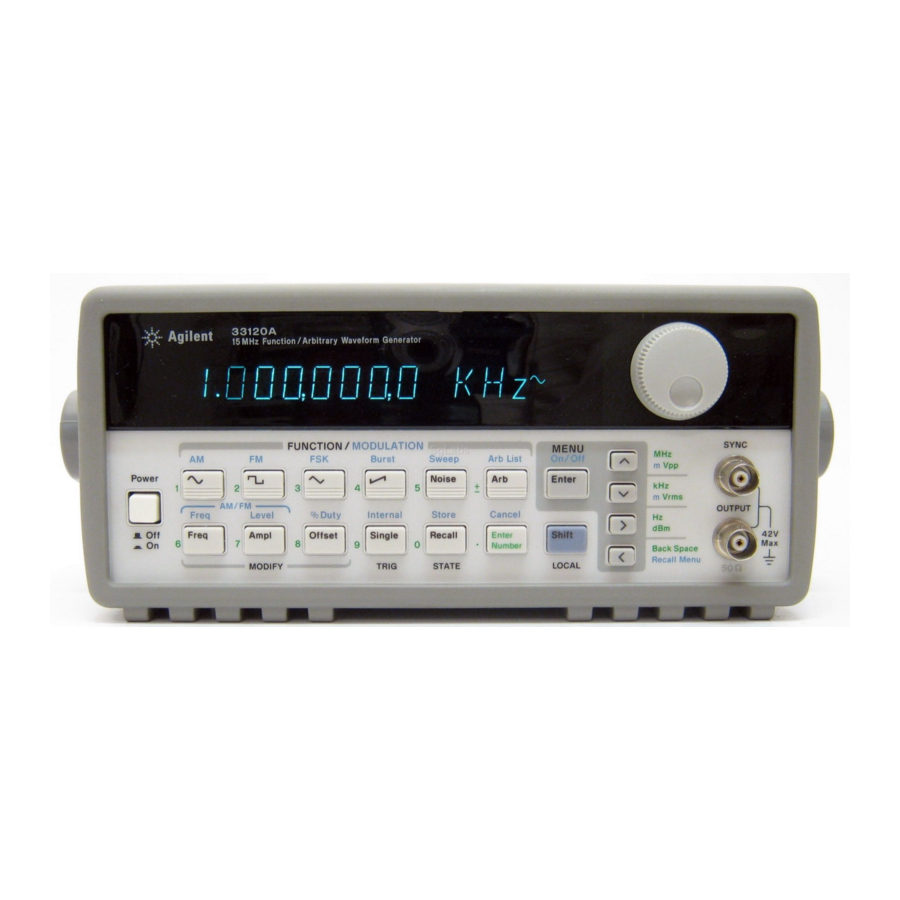
- Page 4 The Front Panel at a Glance 1 Function / Modulation keys 5 Recall / Store instrument state key 2 Menu operation keys 6 Enter Number key 3 Waveform modify keys 7 Shift / Local key 4 Single / Internal Trigger key 8 Enter Number “units”...
- Page 5 Front-Panel Number Entry You can enter numbers from the front-panel using one of three methods. Use the knob and the arrow keys to modify the displayed number. Use the arrow keys to edit individual digits. the flashing digit. Increments the flashing digit. Decrements Moves the flashing digit to the right...
- Page 6 The Front-Panel Menu at a Glance T he menu is organized in a top-down tree structure with three levels. A: MODulation MENU Õ Õ Õ Õ Õ 1: AM SHAPE 2: AM SOURCE 3: FM SHAPE 4: BURST CNT 5: BURST RATE Õ...
- Page 7 Display Annunciators Adrs Function generator is addressed to listen or talk over a remote interface. Function generator is in remote mode (remote interface). Trig Function generator is waiting for a single trigger or external trigger (Burst, Sweep). AM modulation is enabled. FM modulation is enabled.
- Page 8 The Rear Panel at a Glance 1 Chassis ground 5 External Trigger / FSK / Burst modulation input terminal 2 Power-line fuse-holder assembly 3 Power-line voltage setting 6 GPIB (IEEE-488) interface connector 4 AM modulation input terminal 7 RS-232 interface connector Use the front-panel Input / Output Menu to: œ...
- Page 9 Specifications Chapter 8 lists the function generator’s specifications. For information on using the Phase-Lock Option for the 33120A, refer to the User’s and Service Guide included with the Option 001. If you have questions relating to the operation of the 33120A, call 1-800-452-4844 in the United States, or contact your nearest Agilent Technologies Sales Office.
-
Page 11: Table Of Contents
Contents Chapter 1 Quick Start To prepare the function generator for use 15 If the function generator does not turn on 16 To adjust the carrying handle 18 To set the output frequency 19 To set the output amplitude 20 To set a dc offset voltage 21 To set the duty cycle 22 To output a stored arbitrary waveform 23... -
Page 12: Table Of Contents
Contents Chapter 4 Remote Interface Reference SCPI Command Summary 127 Simplified Programming Overview 136 Using the APPLy Command 138 Output Configuration Commands 145 AM Modulation Commands 154 FM Modulation Commands 157 Burst Modulation Commands 160 Frequency-Shift Keying (FSK) Commands 167 Frequency Sweep Commands 170 Arbitrary Waveform Commands 174 Triggering 186... -
Page 13: Table Of Contents
Contents Chapter 6 Application Programs BASIC Programs 244 C Language Programs 244 QuickBASIC Language Programs 247 Using the APPLy Command 248 Using the Low-Level Commands 252 Downloading an Arbitrary Waveform over GPIB 255 Using the Status Registers 261 Downloading an Arbitrary Waveform over RS-232 267 Chapter 7 Tutorial Direct Digital Synthesis 273 Signal Imperfections 276... - Page 14 Contents...
- Page 15 Quick Start...
-
Page 16: Quick Start
Quick Start One of the first things you will want to do with your function generator is to become acquainted with its front panel. We have written the exercises in this chapter to prepare the function generator for use and help you get familiar with some of the front-panel operations. -
Page 17: To Prepare The Function Generator For Use
1 Check the list of supplied items. Verify that you have received the following items with your function generator. If anything is missing, contact your nearest Agilent Technologies Sales Office. One power cord. One RS-232 serial cable. -
Page 18: If The Function Generator Does Not Turn On
The function generator is shipped from the factory with a 500 mAT fuse installed. This is the correct fuse for all line voltages. See the next page if you need to change the power-line fuse. To replace the 500 mAT fuse, order Agilent part number 2110-0458. - Page 19 Chapter 1 Quick Start If the function generator does not turn on Remove the line-voltage selector from . Remove the Remove the power cord the assembly. fuse-holder assembly from the rear panel. Fuse: 500 mAT (for all line voltages) Part Number: 2110-0458 Rotate the line-voltage selector until the Replace the fuse-holder assembly in correct voltage appears in the window.
-
Page 20: To Adjust The Carrying Handle
Chapter 1 Quick Start To adjust the carrying handle To adjust the carrying handle To adjust the position, grasp the handle by the sides and pull outward. Then, rotate the handle to the desired position. Bench-top viewing positions Carrying position... -
Page 21: To Set The Output Frequency
Chapter 1 Quick Start To set the output frequency To set the output frequency At power-on, the function generator outputs a sine wave at 1 kHz with an amplitude of 100 mV peak-to-peak (into a 50 W termination). The following steps show you how to change the frequency to 1.2 MHz. Freq 1 Enable the frequency modify mode. -
Page 22: To Set The Output Amplitude
Chapter 1 Quick Start To set the output amplitude To set the output amplitude At power-on, the function generator outputs a sine wave with an amplitude of 100 mV peak-to-peak (into a 50 W termination). The following steps show you how to change the amplitude to 50 mVrms. Ampl 1 Enable the amplitude modify mode. -
Page 23: To Set A Dc Offset Voltage
Chapter 1 Quick Start To set a dc offset voltage To set a dc offset voltage At power-on, the function generator outputs a sine wave with a dc offset voltage of 0 volts (into a 50 W termination). The following steps show you how to change the offset to –1.5 mVdc. -
Page 24: To Set The Duty Cycle
Chapter 1 Quick Start To set the duty cycle To set the duty cycle Applies only to square waves. At power-on, the duty cycle for square waves is 50%. You can adjust the duty cycle for a square waveform from 20% to 80%, in increments of 1% (for frequencies above 5 MHz, the range is 40% to 60%). -
Page 25: To Output A Stored Arbitrary Waveform
Chapter 1 Quick Start To output a stored arbitrary waveform To output a stored arbitrary waveform There are five built-in arbitrary waveforms stored in non-volatile memory for your use. You can output these waveforms directly from non-volatile memory. The following steps show you how to output an “exponential rise”... -
Page 26: To Output A Dc Voltage
Chapter 1 Quick Start To output a dc voltage To output a dc voltage In addition to generating waveforms, you can also output a dc voltage in the range – 5 Vdc (into a 50 W termination). The following steps show you how to output +155 mVdc. -
Page 27: To Store The Instrument State
Chapter 1 Quick Start To store the instrument state To store the instrument state You can store up to three different instrument states in non-volatile memory. This enables you to recall the entire instrument configuration with just a few key presses from the front panel. The following steps show you how to store and recall a state. - Page 28 Chapter 1 Quick Start To store the instrument state To verify that the state was stored properly, you can turn the power off before recalling the state. Recall 5 Recall the stored instrument state. To recall the stored state, you must use the same memory location used previously to store the state.
-
Page 29: To Rack Mount The Function Generator
Instructions and mounting hardware are included with each rack-mounting kit. Any Agilent System II instrument of the same size can be rack-mounted beside the 33120A Function Generator. Remove the carrying handle, and the front and rear rubber bumpers, before rack-mounting the function generator. - Page 30 Chapter 1 Quick Start To rack mount the function generator To rack mount a single instrument, order adapter kit 5063-9240. To rack mount two instruments side-by-side, order lock-link kit 5061-9694 and flange kit 5063-9212. To install one or two instruments in a sliding support shelf, order shelf 5063-9255, and slide kit 1494-0015 (for a single instrument, also order filler panel 5002-3999).
- Page 31 Front-Panel Menu Operation...
- Page 32 See chapter 3 “Features and Functions,” starting on page 53, for a complete discussion of the function generator’s capabilities and operation. If you purchased the Phase-Lock Option for the 33120A, an additional menu is available from the front panel.
-
Page 33: Front-Panel Menu Reference
Chapter 2 Front-Panel Menu Operation Front-panel menu reference Front-panel menu reference A: MODulation MENU Õ Õ Õ Õ Õ 1: AM SHAPE 2: AM SOURCE 3: FM SHAPE 4: BURST CNT 5: BURST RATE Õ Õ Õ Õ Õ 6: BURST PHAS 7: BURST SRC 8: FSK FREQ 9: FSK RATE... - Page 34 Chapter 2 Front-Panel Menu Operation Front-panel menu reference D: SYStem MENU Õ Õ Õ Õ Õ 1: OUT TERM 2: POWER ON 3: ERROR 4: TEST 5: COMMA 6: REVISION 1: OUT TERM Selects the output termination (50 or high impedance). 2: POWER ON Enables or disables automatic recall of the power-down state.
-
Page 35: A Front-Panel Menu Tutorial
Chapter 2 Front-Panel Menu Operation A front-panel menu tutorial A front-panel menu tutorial This section is a step-by-step tutorial which shows you how to use the front-panel menu. We recommend that you spend a few minutes with this tutorial to get comfortable with the structure and operation of the menu. - Page 36 Chapter 2 Front-Panel Menu Operation A front-panel menu tutorial Messages Displayed During Menu Use ¾ You pressed while on the “ ” level; this is the top level of the TOP OF MENU MENUS menu and you cannot go any higher. To turn off the menu, press Shift Menu On/Off...
- Page 37 Chapter 2 Front-Panel Menu Operation A front-panel menu tutorial Menu Example 1 The following steps show you how to turn on the menu, move up and down between levels, move across the choices on each level, and turn off the menu. In this example, you will enable the function generator to automatically recall the power-down state when power is turned on.
- Page 38 Chapter 2 Front-Panel Menu Operation A front-panel menu tutorial ¿ 5 Move down a level to the “ ” choices. PARAMETER The first parameter choice is “ ” for the command DEFAULT POWER ON (“ ” is the factory setting and is stored in non-volatile memory). DEFAULT DEFAULT >...
- Page 39 Chapter 2 Front-Panel Menu Operation A front-panel menu tutorial Menu Example 2 The following example shows how to use the recall menu feature as a shortcut to set the command back to its original setting. POWER ON You must perform the steps in Example 1 before you start this example. Shift 1 Use recall menu to return to the command.
- Page 40 Chapter 2 Front-Panel Menu Operation A front-panel menu tutorial Menu Example 3 Some commands in the menu require that you enter a numeric parameter value. The following steps show you how to enter a number in the menu. For this example, you will set the number of cycles for the burst modulation mode.
- Page 41 Chapter 2 Front-Panel Menu Operation A front-panel menu tutorial ¿ 4 Move down a level to edit the parameter. BURST CNT The number of cycles should be “1” when you come to this point in the menu for the first time. For this example, you will set the number of cycles to “4”.
-
Page 42: To Select The Output Termination
Chapter 2 Front-Panel Menu Operation To select the output termination To select the output termination The function generator has a fixed output impedance of 50 ohms on the OUTPUT terminal. You can specify whether you are terminating the output into a 50 load or an open circuit. -
Page 43: To Output A Modulated Waveform
Chapter 2 Front-Panel Menu Operation To output a modulated waveform To output a modulated waveform A modulated waveform consists of a carrier and a modulating waveform. In (amplitude modulation), the amplitude of the carrier is varied by the amplitude of the modulating waveform. For this example, you will output an AM waveform with 80% modulation depth. - Page 44 Chapter 2 Front-Panel Menu Operation To output a modulated waveform ¿ 4 Move down a level and verify that “ ” is selected. SINE For the modulating waveform, you can select a sine, square, triangle, ramp, noise, or arbitrary waveform. For this example, you will modulate the carrier with a sine waveform.
- Page 45 Chapter 2 Front-Panel Menu Operation To output a modulated waveform Level 7 Set the modulation depth to 80%. Shift Notice that the annunciator flashes, indicating that the displayed percentage is the depth (also called percent modulation). DEPTH This message appears on the display for approximately 10 seconds. Repeat this step as needed.
-
Page 46: To Output An Fsk Waveform
Chapter 2 Front-Panel Menu Operation To output an FSK waveform To output an FSK waveform You can configure the function generator to “shift” its output frequency between two preset values using (frequency-shift keying) modulation. The rate at which the output shifts between the two frequencies (called the “carrier frequency”... - Page 47 Chapter 2 Front-Panel Menu Operation To output an FSK waveform ¿ 4 Move down a level and set the “hop” frequency to 500 Hz. Notice that the annunciator flashes, indicating that the displayed parameter is for the mode. Also notice that the hop frequency is displayed with fewer digits than the carrier frequency.
- Page 48 Chapter 2 Front-Panel Menu Operation To output an FSK waveform 7 Move across to the command. FSK RATE > 9: FSK RATE ¿ 8 Move down a level and set the “shift” rate to 100 Hz. Notice that the annunciator flashes, indicating that the displayed parameter is for the mode.
-
Page 49: To Output A Burst Waveform
Chapter 2 Front-Panel Menu Operation To output a burst waveform To output a burst waveform You can configure the function generator to output a waveform with a specified number of cycles, called a burst. You can output the burst at a rate determined by the internal rate generator or the signal level on the rear-panel Ext Trig terminal. - Page 50 Chapter 2 Front-Panel Menu Operation To output a burst waveform ¿ 4 Move down to the parameter level and set the count to “3”. Notice that the annunciator flashes, indicating that the displayed Burst parameter is for the burst mode. For more information on editing numbers in the menu, refer to “Menu Example 3”...
-
Page 51: To Output A Frequency Sweep
Chapter 2 Front-Panel Menu Operation To output a frequency sweep To output a frequency sweep In the frequency sweep mode, the function generator “steps” from the start frequency to the stop frequency at a sweep rate which you specify. You can sweep up or down in frequency, and with either linear or logarithmic spacing. - Page 52 Chapter 2 Front-Panel Menu Operation To output a frequency sweep ¿ 4 Move down a level and set the start frequency to 50 Hz. Notice that the annunciator flashes, indicating that the displayed parameter is for the sweep mode. For more information on editing numbers in the menu, refer to “Menu Example 3”...
-
Page 53: To Trigger A Burst Or Sweep
Chapter 2 Front-Panel Menu Operation To trigger a burst or sweep To trigger a burst or sweep You can issue triggers from the front-panel for burst modulation and frequency sweeps using single trigger or internal trigger. Enables single trigger and triggers the generator. -
Page 54: To Turn Off The Comma Separator
Chapter 2 Front-Panel Menu Operation To turn off the comma separator To turn off the comma separator The function generator can display values on the front panel with or without a comma separator. The following steps show how to turn off the comma separator. - Page 55 Features and Functions...
-
Page 56: Features And Functions
Features and Functions You will find that this chapter makes it easy to look up all the details about a particular feature of the function generator. Whether you are operating the function generator from the front panel or over the remote interface, this chapter will be useful. -
Page 57: Output Configuration
Chapter 3 Features and Functions Output Configuration Output Configuration This section contains information to help you configure the function generator for outputting waveforms. You may never have to change some of the parameters discussed here, but they are provided to give you the flexibility you might need. - Page 58 Chapter 3 Features and Functions Output Configuration œ The following matrix shows which output functions are allowed with Output Function each modulation mode. Each “ ” indicates a valid combination. If you (continued) change to a function that is not allowed with the selected modulation, the modulation mode is turned off.
- Page 59 Chapter 3 Features and Functions Output Configuration Output Frequency As shown below, the output frequency range depends on the function currently selected. The default frequency is 1 kHz for all functions. Function Minimum Frequency Maximum Frequency 100 m Hz Sine 15 MHz 100 m Hz Square...
- Page 60 Chapter 3 Features and Functions Output Configuration œ Possible Conflict with Function Change: The output frequency is Output Frequency automatically adjusted if you select a function whose maximum (continued) frequency is less than that of the currently active function. For example, if you output a 1 MHz sine wave and then change the function to triangle wave, the function generator will adjust the output to 100 kHz (the upper limit for triangle waves).
- Page 61 Chapter 3 Features and Functions Output Configuration Output Amplitude As shown below, the output amplitude range depends on the function currently selected and the output termination. The default amplitude is 100 mVpp (into 50 ohms) for all functions. Output Minimum Maximum Function Termination...
- Page 62 Chapter 3 Features and Functions Output Configuration œ Output Amplitude and Output Termination: The output amplitude is Output Amplitude automatically adjusted (and no error is generated) if you change the (continued) output termination. For example, if you set the amplitude to 10 Vpp and then change the termination from 50 ohms to “high impedance”, the displayed amplitude will double to 20 Vpp.
- Page 63 Chapter 3 Features and Functions Output Configuration œ You can set the units for output amplitude to Vpp, Vrms, or dBm. See “Output Units” on page 64 for more information. œ For dc volts, the output level is actually controlled by setting the –...
- Page 64 Chapter 3 Features and Functions Output Configuration DC Offset Voltage At power-on, the dc offset is set to 0 volts. You can set the offset to a positive or negative number with the restrictions shown below. If the specified offset voltage is not valid, the function generator will automatically adjust it to the maximum dc voltage allowed with the present amplitude.
- Page 65 Chapter 3 Features and Functions Output Configuration œ For arbitrary waveforms, the annunciator will turn on if the Offset waveform data has an inherent offset present (if the average is not equal to zero). The function generator calculates the average of the data points and compares the average to zero volts.
- Page 66 Chapter 3 Features and Functions Output Configuration Output Units Applies only to output amplitude (does not affect offset). At power-on, the units for output amplitude are volts peak-to-peak. œ Output units: Vpp , Vrms, or dBm. The default is Vpp. œ...
- Page 67 Chapter 3 Features and Functions Output Configuration Output Termination Applies only to output amplitude and offset voltage. The function generator has a fixed output impedance of 50 ohms on the OUTPUT terminal. You can specify whether you are terminating the output into a 50 ohm load or an open circuit.
- Page 68 Chapter 3 Features and Functions Output Configuration Duty Cycle Applies only to square waves. Duty cycle is specified as a percentage and represents the amount of time per cycle that the square wave is high. Duty Cycle = (where T = frequency œ...
- Page 69 Chapter 3 Features and Functions Output Configuration œ Possible Conflict with Output Frequency: The duty cycle is auto- matically adjusted if you select a frequency that is not valid with the present duty cycle. For example, if you set the duty cycle to 70% and then change the frequency to 8 MHz, the function generator will automatically adjust the duty cycle to 60% (the upper limit for this frequency).
- Page 70 Chapter 3 Features and Functions Output Configuration SYNC Signal A sync signal output is provided on the front-panel SYNC terminal. All of the standard output functions (except dc and noise) have an associated sync signal. For certain applications where you may not want to output the sync signal, you can disable the SYNC terminal.
- Page 71 Chapter 3 Features and Functions Output Configuration Instrument State Storage You can store up to three different instrument states in non-volatile memory. This enables you to recall the entire instrument configuration with a single command from the remote interface or with just a few key presses from the front panel.
- Page 72 Chapter 3 Features and Functions Output Configuration œ When power is turned off, the function generator automatically stores State Storage its state in memory location “0”. You can configure the function (continued) generator to automatically recall the power-down state when power is restored.
-
Page 73: Amplitude Modulation (Am)
Chapter 3 Features and Functions Amplitude Modulation (AM) Amplitude Modulation (AM) A modulated waveform consists of a carrier waveform and a modulating waveform. In , the amplitude of the carrier is varied by the amplitude of the modulating waveform. The function generator will accept an internal modulating signal, an external modulating signal, or both. - Page 74 Chapter 3 Features and Functions Amplitude Modulation (AM) Carrier Waveform Shape œ AM carrier shape: Sine , Square, Triangle, Ramp, or Arbitrary waveform. The default is Sine. œ You cannot use the noise function or dc volts as the carrier waveform. œ...
- Page 75 Chapter 3 Features and Functions Amplitude Modulation (AM) Modulating Waveform Shape The function generator will accept an internal modulating signal, an external modulating signal, or both. œ Modulating waveform shape (internal source): Sine , Square, Triangle, Ramp, Noise, or Arbitrary waveform. The default is Sine. œ...
- Page 76 Chapter 3 Features and Functions Amplitude Modulation (AM) Modulating Waveform Frequency The function generator will accept an internal modulating signal, an external modulating signal, or both. œ Modulating frequency (internal source): 10 mHz to 20 kHz. The default is 100 Hz. œ...
- Page 77 Chapter 3 Features and Functions Amplitude Modulation (AM) Modulating Source The function generator will accept an internal modulating signal, an external modulating signal, or both. œ Modulating source: Internal-External (both) or External only. The default is Both (internal-external). œ The External modulating source is always enabled. œ...
-
Page 78: Frequency Modulation (Fm)
Chapter 3 Features and Functions Frequency Modulation (FM) Frequency Modulation (FM) A modulated waveform consists of a carrier waveform and a modulating waveform. In , the frequency of the carrier is varied by the frequency of the modulating waveform. The function generator will accept only an internal modulating signal (no external source is available). - Page 79 Chapter 3 Features and Functions Frequency Modulation (FM) Carrier Waveform Shape œ FM carrier shape: Sine , Square, Triangle, Ramp, or Arbitrary waveform. The default is Sine. œ You cannot use the noise function or dc volts as the carrier waveform. œ...
- Page 80 Chapter 3 Features and Functions Frequency Modulation (FM) Carrier Frequency œ Carrier frequency: 10 mHz to 15 MHz (100 kHz for triangle and ramp). The default is 1 kHz. œ For arbitrary waveforms, the maximum carrier frequency depends on the number of points specified in the waveform. The five built-in arbitrary waveforms can be output at a maximum of 5 MHz.
- Page 81 Chapter 3 Features and Functions Frequency Modulation (FM) Modulating Waveform Shape The function generator will accept only an internal modulating signal. œ Modulating waveform shape (internal source): Sine , Square, Triangle, Ramp, Noise, or Arbitrary waveform. The default is Sine. œ...
- Page 82 Chapter 3 Features and Functions Frequency Modulation (FM) Peak Frequency Deviation The peak frequency deviation represents the variation in frequency of the modulating waveform from the carrier frequency. œ Peak frequency deviation: 10 mHz to 7.5 MHz. The default is 100 Hz. œ...
-
Page 83: Burst Modulation
Chapter 3 Features and Functions Burst Modulation Burst Modulation You can configure the function generator to output a waveform with a specified number of cycles, called a burst. You can output the burst at a rate determined by the internal rate generator or an external signal applied to the rear-panel connector. - Page 84 Chapter 3 Features and Functions Burst Modulation Burst Trigger Source In the triggered burst mode, the function generator outputs a waveform with the specified number of cycles (burst count) each time a trigger is received. After the specified number of cycles has been output, the function generator waits for the next trigger while outputting no signal (zero volts or the dc offset level).
- Page 85 Chapter 3 Features and Functions Burst Modulation Burst Source In the external gated burst mode, the output waveform is either “on” or “off ” based on the level of the external signal applied to the rear-panel Ext Trig terminal. When the gate signal is true, the function generator outputs a continuous waveform.
- Page 86 Chapter 3 Features and Functions Burst Modulation To Select Burst Modulation œ annunciator turns on when burst modulation is enabled. Burst œ Only one modulation mode can be enabled at a time. When you enable the burst mode, the previous modulation mode is turned off. œ...
- Page 87 Chapter 3 Features and Functions Burst Modulation œ For arbitrary waveforms used as the carrier waveform, the maximum frequency depends on the number of points specified in the waveform. The five built-in arbitrary waveforms can be output at a maximum of 5 MHz (be sure to note the restrictions below).
- Page 88 Chapter 3 Features and Functions Burst Modulation œ For all waveforms used with burst, if the carrier frequency is set Carrier Frequency less than or equal to 100 Hz, the following relationship applies. (continued) Burst Count ˆ 500 seconds For Carrier ˆ 100 Hz Carrier Frequency If you attempt to set the carrier frequency to a value that is not valid, the function generator will automatically adjust the frequency to the...
- Page 89 Chapter 3 Features and Functions Burst Modulation Burst Count The burst count defines the number of cycles to be output per burst. Used only in the triggered burst mode (internal or external source). Certain combinations of burst count and carrier frequency are not allowed.
- Page 90 Chapter 3 Features and Functions Burst Modulation Burst Rate The burst rate defines the frequency at which internally triggered bursts are generated. The burst rate frequency defines the interval between bursts. Used only in the internal triggered burst mode. Keep in mind that the burst rate is different than the “carrier frequency” which specifies the frequency of the bursted signal.
- Page 91 Chapter 3 Features and Functions Burst Modulation Burst Phase The burst phase defines the starting phase of the burst. œ Burst phase: -360 degrees to +360 degrees, in 0.001 degree increments. The default is 0 degrees. œ For sine, square, triangle, and ramp waveforms, 0 degrees is the point at which the waveform crosses zero volts (or the dc offset value), in a positive-going direction.
-
Page 92: Frequency-Shift Keying (Fsk) Modulation
Chapter 3 Features and Functions Frequency-Shift Keying (FSK) Modulation Frequency-Shift Keying (FSK) Modulation You can configure the function generator to “shift” its output frequency between two preset values using modulation. The rate at which the output shifts between the two frequencies (called the “carrier frequency” and the “hop frequency”) is determined by the internal rate generator or the signal level on the rear-panel FSK terminal. - Page 93 Chapter 3 Features and Functions Frequency-Shift Keying (FSK) Modulation FSK Carrier Frequency œ Carrier frequency: 10 mHz to 15 MHz (100 kHz for triangle and ramp). The default is 1 kHz. You can use sine, square, ramp, triangle, or arbitrary waveforms for the carrier waveform. œ...
- Page 94 Chapter 3 Features and Functions Frequency-Shift Keying (FSK) Modulation FSK “Hop” Frequency œ Hop frequency: 10 mHz to 15 MHz (100 kHz for triangle and ramp). The default is 100 Hz. You can use sine, square, ramp, triangle, or arbitrary waveforms for the hop frequency waveshape. œ...
- Page 95 Chapter 3 Features and Functions Frequency-Shift Keying (FSK) Modulation FSK Rate The FSK rate is the rate at which the output frequency “shifts” between the carrier frequency and the hop frequency when you select the internal source. œ FSK rate (internal source): 10 mHz to 50 kHz. The default is 10 Hz. œ...
-
Page 96: Frequency Sweep
Chapter 3 Features and Functions Frequency Sweep Frequency Sweep In the frequency sweep mode, the function generator “steps” from the start frequency to the stop frequency at a sweep rate which you specify. You can sweep up or down in frequency, and with either linear or logarithmic spacing. - Page 97 Chapter 3 Features and Functions Frequency Sweep Start Frequency and Stop Frequency The start frequency and stop frequency set the upper and lower frequency bounds for the sweep. The function generator begins at the start frequency, sweeps to the stop frequency, and then resets back to the start frequency.
- Page 98 Chapter 3 Features and Functions Frequency Sweep Sweep Time The sweep time specifies the number of seconds required to sweep from the start frequency to the stop frequency. The number of frequency points in the sweep depends on the sweep time you select and is automatically calculated by the function generator.
- Page 99 Chapter 3 Features and Functions Frequency Sweep Sweep Trigger Source In the triggered sweep mode, the function generator outputs a single sweep each time a trigger is received. After one sweep from the start frequency to the stop frequency, the function generator waits for the next trigger while outputting the start frequency.
-
Page 100: Triggering
Chapter 3 Features and Functions Triggering Triggering Applies only to bursts and frequency sweep. You can issue triggers for bursts and sweeps using internal triggering, single triggering, or external triggering. œ Internal or “automatic” triggering is enabled when you turn on the function generator. - Page 101 Chapter 3 Features and Functions Triggering Trigger Source Choices Applies only to burst and sweep. You must specify the source from which the function generator will accept a trigger. œ From the front panel, the function generator will accept a single trigger, a hardware trigger from the Ext Trig terminal, or continuously output bursts or sweeps using the internal trigger.
- Page 102 Chapter 3 Features and Functions Triggering Single Triggering In the single trigger mode (front panel only), you can manually trigger the function generator by pressing the front-panel key. The function generator outputs one burst or Single initiates one sweep each time you press the key. The Trig annunciator turns on when the function generator is waiting for a single trigger.
- Page 103 Chapter 3 Features and Functions Triggering Software (Bus) Triggering The bus trigger mode is available only from the remote interface. This mode is similar to the single trigger mode from the front panel, but you trigger the function generator by sending a bus trigger command.
- Page 104 Chapter 3 Features and Functions Triggering Ext Trig / FSK / Burst Input Terminal INPUT > 1 This terminal is used in the following modes: œ Triggered Sweep Mode: Press or execute TRIG:SOUR EXT Single from the remote interface to enable the triggered sweep mode (sweeps must be enabled).
-
Page 105: Arbitrary Waveforms
Chapter 3 Features and Functions Arbitrary Waveforms Arbitrary Waveforms There are five built-in arbitrary waveforms stored in non-volatile memory. You can also download up to four user-defined waveforms into non-volatile memory. Each waveform can contain between 8 and 16,000 data points. Refer to chapter 7, “Tutorial”, for more information on the internal operation of downloading and outputting an arbitrary waveform. - Page 106 Chapter 3 Features and Functions Arbitrary Waveforms ¿ 4 Move down a level to the “ ” choices. PARAMETER The first parameter choice is “ ” for the command. CLEAR MEM NEW ARB If you have previously downloaded any user-defined waveforms, you will also see commands like “...
- Page 107 Chapter 3 Features and Functions Arbitrary Waveforms 9 Save the change and turn off the menu. Enter The function generator beeps and displays a message to show that the change is now in effect. You are then exited from the menu. COMPUTING Shift 10 Use Recall Menu to return to the...
- Page 108 Chapter 3 Features and Functions Arbitrary Waveforms 14 Increment to point “299” and set the end point to a value of “1”. Use the left/right arrow keys to move between the point field (left) and the floating-point value (right). As you modify the value, the end point is output.
- Page 109 Chapter 3 Features and Functions Arbitrary Waveforms ¿ 19 Move down a level to save the waveform in non-volatile memory. At this point, the pulse waveform is being output from volatile memory. You can store up to four user-defined waveforms in non-volatile memory. From the front panel, you can save the waveform using one of the following names: ARB1, ARB2, ARB3, or ARB4.
- Page 110 Chapter 3 Features and Functions Arbitrary Waveforms Additional Information on Arbitrary Waveforms œ Press the key to output the arbitrary waveform currently selected (to scroll through the waveform choices and make a selection, press Arb List œ In addition to creating a new arbitrary waveform from the front panel, you can also edit any existing user-defined waveforms.
-
Page 111: System-Related Operations
Chapter 3 Features and Functions System-Related Operations System-Related Operations This section gives information on topics such as power-down recall, self-test, error conditions, and front-panel display control. This information is not directly related to waveform generation but is an important part of operating the function generator. Power-Down Recall Mode When power is turned off, the function generator automatically stores its state in memory location “0”. - Page 112 Chapter 3 Features and Functions System-Related Operations Error Conditions When the front-panel annunciator turns on, one or more ERROR command syntax or hardware errors have been detected. A record of up to 20 errors can be stored in the function generator’s error queue. See chapter 5, “Error Messages,”...
- Page 113 ” is displayed and the FAIL ERROR annunciator turns on. See the Service Guide for instructions on returning the function generator to Agilent for service. œ Front-Panel Operation: 4: TEST (SYS MENU) Another way to perform the complete self-test from the front panel...
- Page 114 Chapter 3 Features and Functions System-Related Operations Display Control To speed up the rate at which the function generator can make configuration changes, or for security reasons, you may want to turn off the front-panel display. From the remote interface, you can also display a message containing up to 11 characters on the front panel.
- Page 115 œ Front-Panel Operation: 6: REVISION (SYS MENU) X.X-X.X-X.X œ Remote Interface Operation: Returns “HEWLETT-PACKARD,33120A,0,X.X-X.X-X.X” *IDN? Be sure to dimension a string variable with at least 40 characters.
-
Page 116: Remote Interface Configuration
œ Your bus controller has its own address. Be sure to avoid using GPIB the bus controller’s address for any instrument on the interface bus. Agilent controllers generally use address “21”. œ Front-Panel Operation: 1: HPIB ADDR (I/O MENU) See also “To set the address,”... - Page 117 Chapter 3 Features and Functions Remote Interface Configuration Remote Interface Selection The function generator is shipped with both an -488) GPIB IEEE interface and an -232 interface. Only one interface can be enabled at a time. The GPIB interface is selected when the function generator is shipped from the factory.
- Page 118 Chapter 3 Features and Functions Remote Interface Configuration Baud Rate Selection ( -232) You can select one of six baud rates for -232 operation. The rate is set to 9600 baud when the function generator is shipped from the factory. The baud rate can be set from the front-panel only.
- Page 119 Chapter 3 Features and Functions Remote Interface Configuration Programming Language Query The function generator complies with the rules and conventions of the present version of (Standard Commands for Programmable SCPI Instruments). You can verify from the front-panel that the SCPI language is selected.
-
Page 120: Calibration Overview
Chapter 3 Features and Functions Calibration Overview Calibration Overview This section gives an overview of the calibration features of the function generator. For a more detailed discussion of the calibration procedures, see chapter 4 in the Service Guide. Calibration Security This feature allows you to enter a security code to prevent accidental or unauthorized calibrations of the function generator. - Page 121 Chapter 3 Features and Functions Calibration Overview To Unsecure for Calibration You can unsecure the function generator for calibration either from the front panel or over the remote interface. The function generator is secured when shipped from the factory and the security code is set to “HP033120”. œ...
- Page 122 Chapter 3 Features and Functions Calibration Overview To Secure Against Calibration You can secure the function generator against accidental calibration either from the front panel or over the remote interface. The function generator is secured when shipped from the factory and the security code is set to “HP033120”. Be sure to read the security code rules on page 118 before attempting to secure the function generator.
- Page 123 Chapter 3 Features and Functions Calibration Overview To Change the Security Code To change the security code, you must first unsecure the function generator, and then enter a new code. Be sure to read the security code rules on page 118 before changing the security code.
- Page 124 Chapter 3 Features and Functions Calibration Overview Calibration Message You can use the calibration message feature to record calibration information about your function generator. For example, you can store such information as the last calibration date, the next calibration due date, the instrument serial number, or even the name and phone number of the person to contact for a new calibration.
-
Page 125: Power-On And Reset State
Chapter 3 Features and Functions Power-On and Reset State Power-On and Reset State œ The parameters marked with a bullet ( ) are stored in memory. non-volatile The factory settings are shown. Output Configuration Power-On/Reset State Function Sine wave Frequency 1 kHz Amplitude (into 50 ohms) 100 mV peak-to-peak... - Page 127 Remote Interface Reference...
- Page 128 Remote Interface Reference œ SCPI Command Summary, starting on page 127 Õ œ Simplified Programming Overview, starting on page 136 œ Using the APPLy Command, starting on page 138 œ Output Configuration Commands, starting on page 145 œ AM Modulation Commands, starting on page 154 œ...
-
Page 129: Scpi Command Summary
Chapter 4 Remote Interface Reference SCPI Command Summary SCPI Command Summary This section summarizes the (Standard Commands for SCPI Programmable Instruments) commands available to program the function generator over the remote interface. Refer to the later sections in this chapter for more complete details on each command. Throughout this manual, the following conventions are used for command syntax. - Page 130 Chapter 4 Remote Interface Reference SCPI Command Summary Output Configuration Commands (see page 145 for more information) [SOURce:] FUNCtion:SHAPe { SINusoid |SQUare|TRIangle|RAMP|NOISe|DC|USER} FUNCtion:SHAPe? [SOURce:] FREQuency {< frequency >|MINimum|MAXimum} FREQuency? [MINimum|MAXimum] [SOURce:] percent PULSe:DCYCle {< >|MINimum|MAXimum} PULSe:DCYCle? [MINimum|MAXimum] [SOURce:] VOLTage {< amplitude >|MINimum|MAXimum} VOLTage? [MINimum|MAXimum]...
- Page 131 Chapter 4 Remote Interface Reference SCPI Command Summary Modulation Commands (see page 154 for more information) [SOURce:] depth in percent AM:DEPTh {< >|MINimum|MAXimum} AM:DEPTh? [MINimum|MAXimum] AM:INTernal:FUNCtion { SINusoid |SQUare|TRIangle|RAMP|NOISe|USER} AM:INTernal:FUNCtion? frequency AM:INTernal:FREQuency {< >|MINimum|MAXimum} AM:INTernal:FREQuency? [MINimum|MAXimum] AM:SOURce { BOTH |EXTernal} AM:SOURce? AM:STATe {OFF|ON} AM:STATe?
- Page 132 Chapter 4 Remote Interface Reference SCPI Command Summary Frequency-Shift Keying (FSK) Commands (see page 167 for more information) [SOURce:] FSKey:FREQuency {< frequency >|MINimum|MAXimum} FSKey:FREQuency? [MINimum|MAXimum] rate in Hz FSKey:INTernal:RATE {< >|MINimum|MAXimum} FSKey:INTernal:RATE? [MINimum|MAXimum] INTernal FSKey:SOURce { |EXTernal} FSKey:SOURce? FSKey:STATe {OFF|ON} FSKey:STATe? Sweep Commands (see page 170 for more information)
- Page 133 Chapter 4 Remote Interface Reference SCPI Command Summary Arbitrary Waveform Commands (see page 174 for more information) [SOURce:] arb name > |VOLATILE} FUNCtion:USER {< FUNCtion:USER? FUNCtion:SHAPe USER FUNCtion:SHAPe? Specify 1 of the 5 built-in waveforms or a user-defined waveform name. >, .
- Page 134 Chapter 4 Remote Interface Reference SCPI Command Summary Triggering Commands (see page 186 for more information) IMMediate TRIGger:SOURce { |EXTernal|BUS} TRIGger:SOURce? TRIGger:SLOPe { POSitive |NEGative} TRIGger:SLOPe? *TRG System-Related Commands (see page 188 for more information) DISPlay {OFF| DISPlay? quoted string DISPlay:TEXT <...
- Page 135 Chapter 4 Remote Interface Reference SCPI Command Summary Calibration Commands (see page 193 for more information) CALibration? CALibration:COUNt? new code CALibration:SECure:CODE < > CALibration:SECure:STATe {OFF| },< code > CALibration:SECure:STATe? . . . CALibration:SETup <0|1|2|3| |84> CALibration:SETup? quoted string CALibration:STRing < >...
- Page 136 Chapter 4 Remote Interface Reference SCPI Command Summary Status Reporting Commands (see page 209 for more information) SYSTem:ERRor? *CLS *ESE < enable value > *ESE? *ESR? *OPC *OPC? *PSC {0| *PSC? enable value *SRE < > *SRE? *STB? *WAI Default parameters are shown in bold.
- Page 137 Chapter 4 Remote Interface Reference SCPI Command Summary IEEE-488.2 Common Commands (see page 209 for more information) *CLS *ESE < enable value > *ESE? *ESR? *IDN? *OPC *OPC? *PSC {0| *PSC? *RST State 0 is the instrument state at power down. *SAV {0|1|2|3} States 1, 2, and 3 are user-defined instrument states.
-
Page 138: Simplified Programming Overview
Chapter 4 Remote Interface Reference Simplified Programming Overview Simplified Programming Overview This section gives an overview of the basic techniques used to program First-time the function generator over the remote interface. This section is only an SCPI users, see page 211. overview and does not give all of the details you will need to write your own application programs. - Page 139 Chapter 4 Remote Interface Reference Simplified Programming Overview Reading a Query Response Only the query commands (commands that end with “ ? ”) will instruct the function generator to send a response message. Queries return either output values or internal instrument settings. For example, the following statements executed from your computer will read the function generator’s error queue and print the most recent error: Dimension string array (80 elements)
-
Page 140: Using The Apply Command
Chapter 4 Remote Interface Reference Using the APPLy Command Using the APPLy Command See also “Output Configuration,” starting on page 55 in chapter 3. The APPLy command provides the most straightforward method to program the function generator over the remote interface. You can select the function, frequency, amplitude, and offset all in one command. - Page 141 Chapter 4 Remote Interface Reference Using the APPLy Command œ For arbitrary waveforms that you create and download to memory, the maximum frequency depends on the number of points specified in the waveform. As shown below, the maximum output frequency decreases as you specify more points in the waveform.
- Page 142 Chapter 4 Remote Interface Reference Using the APPLy Command Output Amplitude œ For the amplitude parameter of the APPLy command, the output amplitude range depends on the function currently selected and the output termination. You can substitute “ imum”, “ imum”, or “...
- Page 143 Chapter 4 Remote Interface Reference Using the APPLy Command œ Possible Conflict with Function Change: The output amplitude is automatically adjusted if you select a function whose maximum amplitude is less than that of the currently active function. This conflict may arise when the output units are Vrms or dBm due to the differences in crest factor for the output functions.
- Page 144 Chapter 4 Remote Interface Reference Using the APPLy Command DC Offset Voltage œ For the offset parameter of the APPLy command, you can substitute “ imum”, “ imum”, or “ ault” in place of a specific value for the parameter. selects the smallest dc offset voltage for the selected function (0 volts).
- Page 145 Chapter 4 Remote Interface Reference Using the APPLy Command APPLy Command Syntax œ Because of the use of optional parameters in the APPLy commands (enclosed in square brackets), you must specify frequency to use the amplitude parameter, and you must specify both frequency and amplitude to use the offset parameter.
- Page 146 Chapter 4 Remote Interface Reference Using the APPLy Command frequency amplitude offset APPLy:NOISe [< |DEFault> [,< > [,< >] ]] Output noise with the specified amplitude and dc offset. The waveform is output as soon as the command is executed. œ...
-
Page 147: Output Configuration Commands
Chapter 4 Remote Interface Reference Output Configuration Commands Output Configuration Commands See also “Output Configuration,” starting on page 55 in chapter 3. This section describes the low-level commands used to program the function generator. Although the APPLy command provides the most straightforward method to program the function generator, the low-level commands give you more flexibility to change individual parameters. - Page 148 Chapter 4 Remote Interface Reference Output Configuration Commands frequency FREQuency {< >|MINimum|MAXimum} Set the output frequency. selects the lowest frequency allowed for the currently active function. selects the highest frequency allowed for the currently active function. The default frequency is 1 kHz for all functions.
- Page 149 Chapter 4 Remote Interface Reference Output Configuration Commands percent PULSe:DCYCle {< >|MINimum|MAXimum} Set the duty cycle in percent for square waves only. Duty cycle represents the amount of time per cycle that the square wave is high. The default is 50%. [ Stored in volatile memory ] œ...
- Page 150 Chapter 4 Remote Interface Reference Output Configuration Commands amplitude VOLTage {< >|MINimum|MAXimum} Set the output amplitude for the currently active function. selects the smallest amplitude allowed for the selected function (50 mVpp into 50 ohms). selects the largest amplitude allowed (10 Vpp into 50 ohms).
- Page 151 Chapter 4 Remote Interface Reference Output Configuration Commands œ Possible Conflict with Function Change: The output amplitude is automatically adjusted if you select a function whose maximum amplitude is less than that of the currently active function. This conflict may arise when the output units are Vrms or dBm due to the differences in crest factor for the output functions.
- Page 152 Chapter 4 Remote Interface Reference Output Configuration Commands œ DC Offset and Output Termination: The offset voltage is auto- VOLTage:OFFSet matically adjusted (and no error is generated) if you change the (continued) output termination. For example, if you set the offset to 100 mVdc and then change the termination from 50 ohms to “high impedance”, the displayed offset will double to 200 mVdc.
- Page 153 Chapter 4 Remote Interface Reference Output Configuration Commands OUTPut:LOAD {50|INFinity|MINimum|MAXimum} Select the output termination for output amplitude and offset voltage. The function generator has a fixed output impedance of 50 ohms on the OUTPUT terminal. You can specify whether you are terminating the output into a 50 ohm load or an open circuit.
- Page 154 Chapter 4 Remote Interface Reference Output Configuration Commands *SAV {0|1|2|3} Store up to four different instrument configurations. [ Stored in non-volatile memory ] œ Four memory locations (numbered 0, 1, 2, and 3) are available to store instrument configurations. The state storage feature “remembers” the function (including arbitrary waveforms), frequency, amplitude, dc offset, duty cycle, as well as any modulation parameters.
- Page 155 Chapter 4 Remote Interface Reference Output Configuration Commands *RCL {0|1|2|3} Recall a previously stored state. To recall a stored state, you must use the same memory location used previously to store the state. œ You cannot recall the instrument state from a memory location that was not previously specified as a storage location.
-
Page 156: Am Modulation Commands
Chapter 4 Remote Interface Reference AM Modulation Commands AM Modulation Commands See also “Amplitude Modulation,” starting on page 71 in chapter 3. AM Overview The following is an overview of the steps required to generate an waveform. The commands used for are listed on the next page. - Page 157 Chapter 4 Remote Interface Reference AM Modulation Commands AM Commands Use the APPLy command or the equivalent FUNC:SHAP, FREQ, VOLT, and VOLT:OFFS commands to configure the carrier waveform. Set the carrier frequency between 100 Hz and 15 MHz (100 kHz for triangle and ramp).
- Page 158 Chapter 4 Remote Interface Reference AM Modulation Commands AM:SOURce {BOTH|EXTernal} Select the source of the modulating signal. The function generator will accept an internal modulating signal, an external modulating signal, or both. The default is BOTH. [ Stored in volatile memory ] œ...
-
Page 159: Fm Modulation Commands
Chapter 4 Remote Interface Reference FM Modulation Commands FM Modulation Commands See also “Frequency Modulation,” starting on page 76 in chapter 3. FM Overview The following is an overview of the steps required to generate an waveform. The commands used for are listed on the next page. - Page 160 Chapter 4 Remote Interface Reference FM Modulation Commands FM Commands Use the APPLy command or the equivalent FUNC:SHAP, FREQ, VOLT, and VOLT:OFFS commands to configure the carrier waveform. Set the carrier frequency between 10 mHz and 15 MHz (100 kHz for triangle and ramp).
- Page 161 Chapter 4 Remote Interface Reference FM Modulation Commands FM:INTernal:FUNCtion {SINusoid|SQUare|TRIangle|RAMP|NOISe|USER} Select the shape of the modulating waveform. You can use the noise function as the modulating waveform. However, you cannot use the noise function or dc volts as the carrier waveform. The default is SIN. [ Stored in volatile memory ] FM:INTernal:FUNCtion? Query the shape of the modulating waveform.
-
Page 162: Burst Modulation Commands
Chapter 4 Remote Interface Reference Burst Modulation Commands Burst Modulation Commands See also “Burst Modulation,” starting on page 81 in chapter 3. Burst Modulation Overview The following is an overview of the steps required to generate a burst-modulated waveform. The commands used for burst modulation are listed on page 162. - Page 163 Chapter 4 Remote Interface Reference Burst Modulation Commands 1 Set up the burst carrier waveform. Use the APPLy command or the equivalent FUNC:SHAP, FREQ, VOLT, and VOLT:OFFS commands to select the function, frequency, amplitude, and offset of the carrier waveform. You can select a sine, square, triangle, ramp, or arbitrary waveform for the carrier.
- Page 164 Chapter 4 Remote Interface Reference Burst Modulation Commands Burst Modulation Commands Use the APPLy command or the equivalent FUNC:SHAP, FREQ, VOLT, and VOLT:OFFS commands to configure the carrier waveform. Set the carrier frequency between 10 mHz and 5 MHz (100 kHz for triangle and ramp).
- Page 165 Chapter 4 Remote Interface Reference Burst Modulation Commands œ For all waveforms used with burst, if the carrier frequency is set less than or equal to 100 Hz, the following relationship applies. Count Burst ˆ 500 seconds For Carrier ˆ 100 Hz Carrier Frequency If you attempt to set the carrier frequency to a value that is not valid, the function generator will automatically adjust the frequency to the...
- Page 166 Chapter 4 Remote Interface Reference Burst Modulation Commands frequency BM:INTernal:RATE {< >|MINimum|MAXimum} Set the burst rate for internally triggered bursts. The burst rate frequency defines the interval between bursts. Select from 10 mHz to 50 kHz. The default is 100 Hz. = 10 mHz.
- Page 167 Chapter 4 Remote Interface Reference Burst Modulation Commands BM:STATe {OFF|ON} Disable or enable burst modulation. To ensure proper operation, you should enable the burst mode after you have set up the other modulation parameters. Only one modulation mode can be enabled at a time. When you enable the burst mode, the previous modulation mode is turned off.
- Page 168 Chapter 4 Remote Interface Reference Burst Modulation Commands œ When the External gate source is selected (“gated” burst mode), the TRIGger:SOURce specified trigger source is ignored. The external gated mode overrides (continued) the triggered mode source. œ To ensure synchronization when the Bus source is selected, send the *WAI (wait) command.
-
Page 169: Frequency-Shift Keying (Fsk) Commands
Chapter 4 Remote Interface Reference Frequency-Shift Keying (FSK) Commands Frequency-Shift Keying (FSK) Commands See also “FSK Modulation,” starting on page 90 in chapter 3. FSK Overview The following is an overview of the steps required to generate an waveform. The commands used for are listed on the next page. - Page 170 Chapter 4 Remote Interface Reference Frequency-Shift Keying (FSK) Commands FSK Commands Use the APPLy command or the equivalent FUNC:SHAP, FREQ, VOLT, and VOLT:OFFS commands to configure the carrier waveform. Set the carrier frequency between 10 mHz and 15 MHz (100 kHz for triangle and ramp).
- Page 171 Chapter 4 Remote Interface Reference Frequency-Shift Keying (FSK) Commands FSKey:SOURce {INTernal|EXTernal} Select an internal or external source. The default is INT. [ Stored in volatile memory ] œ When the internal source is selected, the rate at which the output frequency “shifts”...
-
Page 172: Frequency Sweep Commands
Chapter 4 Remote Interface Reference Frequency Sweep Commands Frequency Sweep Commands See also “Frequency Sweep,” starting on page 94 in chapter 3. Sweep Overview The following is an overview of the steps required to generate a frequency sweep. The commands used for frequency sweep are listed on the next page. - Page 173 Chapter 4 Remote Interface Reference Frequency Sweep Commands Sweep Commands To sweep up in frequency, set the start frequency < stop frequency. To sweep down in frequency, set the start frequency > stop frequency. frequency FREQuency:STARt {< >|MINimum|MAXimum} Set the start frequency. Select from 10 mHz to 15 MHz (100 kHz for triangle and ramp).
- Page 174 Chapter 4 Remote Interface Reference Frequency Sweep Commands SWEep:TIME? [MINimum|MAXimum] Query the sweep time. Returns a value in seconds. SWEep:STATe {OFF|ON} Disable or enable the sweep mode. To ensure proper operation, you should enable the sweep mode after you have set up the other sweep parameters.
- Page 175 Chapter 4 Remote Interface Reference Frequency Sweep Commands œ You can use the *OPC? (operation complete query) command or the *OPC (operation complete) command to signal when the sweep is complete. The *OPC? command returns “1” to the output buffer when the sweep is complete.
-
Page 176: Arbitrary Waveform Commands
Chapter 4 Remote Interface Reference Arbitrary Waveform Commands Arbitrary Waveform Commands See also “Arbitrary Waveforms” starting on page 103 in chapter 3. Arbitrary Waveform Overview The following is an overview of the steps required to download and output an arbitrary waveform over the remote interface. The commands used for arbitrary waveforms are listed on page 176. - Page 177 Chapter 4 Remote Interface Reference Arbitrary Waveform Commands 3 Copy the arbitrary waveform to non-volatile memory. You can output the arbitrary waveform directly from volatile memory (as described in step 2) or you can copy the waveform to non-volatile memory. Use the DATA:COPY command to copy the waveform to non-volatile memory.
- Page 178 Chapter 4 Remote Interface Reference Arbitrary Waveform Commands Arbitrary Waveform Commands arb name FUNCtion:USER {< >|VOLATILE} Select one of the five built-in arbitrary waveforms, one of four user-defined waveforms, or the waveform currently downloaded to memory. VOLATILE œ The names of the five built-in arbitrary waveforms are: “...
- Page 179 Chapter 4 Remote Interface Reference Arbitrary Waveform Commands FUNCtion:SHAPe USER Select the function and output the selected arbitrary waveform. When executed, this command outputs the arbitrary waveform currently selected by the FUNC:USER command. The selected waveform is output using the previously selected frequency, amplitude, and offset settings.
- Page 180 Chapter 4 Remote Interface Reference Arbitrary Waveform Commands >, . . . value value DATA VOLATILE, < >, < Download floating-point values between -1 and +1 into volatile memory. You can download between 8 and 16,000 points per waveform. œ The values -1 and +1 correspond to the peak values of the waveform. For example, if you set the amplitude to 10 Vpp, “-1”...
- Page 181 Chapter 4 Remote Interface Reference Arbitrary Waveform Commands >, . . . } binary block>|<value value DATA:DAC VOLATILE, {< >, < Download binary integer values between -2047 and +2047 into volatile memory. You can download between 8 and 16,000 points per waveform -488.2 binary block format or as a list of values.
- Page 182 Chapter 4 Remote Interface Reference Arbitrary Waveform Commands œ To download binary data over the -232 interface, you must select DATA:DAC VOLATILE 8 data bits with no parity. See “RS-232 Interface Configuration” on (continued) page 195 for more information. œ The following statement shows how to use the DATA:DAC VOLATILE command to download eight integer points using the binary block format (see also “Using the IEEE-488.2 Binary Block Format”...
- Page 183 Chapter 4 Remote Interface Reference Arbitrary Waveform Commands arb name DATA:ATTRibute:AVERage? [< >] Query the arithmetic average of all data points for the specified arbitrary waveform. The default arb name is the arbitrary waveform currently active (selected with FUNC:USER command). œ...
- Page 184 Chapter 4 Remote Interface Reference Arbitrary Waveform Commands DATA:CATalog? List the names of all waveforms currently downloaded to memory. Returns the names of the five built-in waveforms (non-volatile memory), “ ” if a waveform is currently downloaded to volatile memory, VOLATILE and all user-defined waveforms downloaded to non-volatile memory.
- Page 185 Chapter 4 Remote Interface Reference Arbitrary Waveform Commands œ If you copy to a waveform name that already exists, the previous waveform is overwritten (no error is generated). However, you cannot overwrite any of the five built-in waveforms. œ Up to four user-defined waveforms can be stored in non-volatile memory.
- Page 186 Chapter 4 Remote Interface Reference Arbitrary Waveform Commands DATA:DELete:ALL Delete all user-defined arbitrary waveforms from memory. This command deletes the waveform in memory and all user-defined VOLATILE waveforms in non-volatile memory. The five built-in waveforms in non-volatile memory are not deleted. œ...
- Page 187 Chapter 4 Remote Interface Reference Arbitrary Waveform Commands DATA:NVOLatile:FREE? Query the number of non-volatile memory slots available to store user-defined waveforms. Non-volatile waveform memory is divided into four 16k-point slots. This command returns the number of memory slots available to store user-defined waveforms: “0” (memory is full), “1”, “2”, “3”, or “4”.
- Page 188 Chapter 4 Remote Interface Reference Triggering Triggering See also “Triggering,” starting on page 98 in chapter 3. First-time Applies only to burst modulation and frequency sweep. You can issue SCPI users, triggers for bursts and sweeps using an immediate trigger, an external see page 211.
- Page 189 Chapter 4 Remote Interface Reference Triggering œ To ensure synchronization when the Bus source is selected, send the *WAI (wait) command. When the *WAI command is executed, the function generator waits for all pending operations to complete before executing any additional commands. For example, the following command string guarantees that the first trigger is accepted and executed before the second trigger is recognized.
-
Page 190: System-Related Commands
Chapter 4 Remote Interface Reference System-Related Commands System-Related Commands See also “System-Related Operations,” starting on page 109 in chapter 3. DISPlay {OFF|ON} Turn the front-panel display off or on. When the display is turned off, output parameters are not sent to the display and all annunciators except are disabled. - Page 191 Chapter 4 Remote Interface Reference System-Related Commands DISPlay:TEXT? Query the message sent to the front panel and return a quoted string. For example, the query returns a string such as "HELLO". DISPlay:TEXT:CLEar Clear the message displayed on the front panel. SYSTem:BEEPer Issue a single beep immediately.
- Page 192 œ The command returns a string with the following format (be sure to dimension a string variable with at least 40 characters): HEWLETT-PACKARD,33120A,0,X.X-X.X-X.X *RST Reset the function generator to its default state (see “Power-On and Reset State”...
- Page 193 Chapter 4 Remote Interface Reference System-Related Commands *SAV {0|1|2|3} Store up to four different instrument configurations. [ Stored in non-volatile memory ] œ Four memory locations (numbered 0, 1, 2, and 3) are available to store instrument configurations. The state storage feature “remembers” the function (including arbitrary waveforms), frequency, amplitude, dc offset, duty cycle, as well as any modulation parameters.
- Page 194 Chapter 4 Remote Interface Reference System-Related Commands *RCL {0|1|2|3} Recall a previously stored state. To recall a stored state, you must use the same memory location used previously to store the state. œ You cannot recall the instrument state from a memory location that was not previously specified as a storage location.
-
Page 195: Calibration Commands
Chapter 4 Remote Interface Reference Calibration Commands Calibration Commands See “Calibration Overview” starting on page 118 for an overview of the calibration features of the function generator. For a more detailed discussion of the calibration procedures, see chapter 4 in the Service Guide. CALibration? Perform a calibration using the specified calibration value (CAL:VAL command). - Page 196 Chapter 4 Remote Interface Reference Calibration Commands CALibration:SETup <0|1|2|3| . . . |84> Configure the function generator’s internal state for each of the calibration steps to be performed. CALibration:SETup? Query the calibration setup number. Returns a value between 0 and 84. quoted string CALibration:STRing <...
-
Page 197: Rs-232 Interface Configuration
Chapter 4 Remote Interface Reference RS-232 Interface Configuration RS-232 Interface Configuration See also “Remote Interface Configuration,” on page 114 in chapter 3. You connect the function generator to the -232 interface using the 9-pin ( -9) serial connector on the rear panel. The function generator is configured as a (Data Terminal Equipment) device. - Page 198 Chapter 4 Remote Interface Reference RS-232 Interface Configuration RS-232 Data Frame Format A character frame consists of all the transmitted bits that make up a single character. The frame is defined as the characters from the start bit to the last stop bit, inclusively. Within the frame, you can select the baud rate, number of data bits, and parity type.
- Page 199 Chapter 4 Remote Interface Reference RS-232 Interface Configuration DB-9 Serial Connection If your computer or terminal has a 9-pin serial port with a male connector, use the null-modem cable included with the 34398A Cable Kit. This cable has a 9-pin female connector on each end.
- Page 200 Chapter 4 Remote Interface Reference RS-232 Interface Configuration DTR / DSR Handshake Protocol The function generator is configured as a (Data Terminal Equipment) device and uses the (Data Terminal Ready) and (Data Set Ready) lines of the -232 interface to handshake. The function generator uses line to send a hold-off signal.
- Page 201 Chapter 4 Remote Interface Reference RS-232 Interface Configuration The function generator holds the line while output is FALSE suspended. A form of interface deadlock exists until the controller asserts the line to allow the function generator to complete TRUE the transmission. You can break the interface deadlock by sending the <Ctrl-C>...
-
Page 202: Rs-232 Interface Commands
Chapter 4 Remote Interface Reference RS-232 Interface Commands RS-232 Interface Commands Use the front-panel I/O MENU to select the baud rate, parity, and number of data bits (see pages 219 and 220 for more information). SYSTem:LOCal Place the function generator in the local mode for -232 operation. -
Page 203: The Scpi Status Registers
Chapter 4 Remote Interface Reference The SCPI Status Registers The SCPI Status Registers The function generator uses the Status Byte register group and the Standard Event register group to record various instrument conditions. A diagram of the status system is shown on the next page. SCPI An example program is included in chapter 6, “Application Programs,”... - Page 204 Chapter 4 Remote Interface Reference The SCPI Status Registers SCPI Status System...
- Page 205 Chapter 4 Remote Interface Reference The SCPI Status Registers The Status Byte Register The Status Byte summary register reports conditions from the other status registers. Query data that is waiting in the function generator’s output buffer is immediately reported through the “message available” bit (bit 4).
- Page 206 Chapter 4 Remote Interface Reference The SCPI Status Registers Using Service Request ( ) and Serial POLL You must configure your bus controller to respond to the -488 IEEE service request ( ) interrupt to use this capability. Use the Status Byte enable register (*SRE command) to select which summary bits will set the low-level -488 service request signal.
- Page 207 Chapter 4 Remote Interface Reference The SCPI Status Registers Using *STB? to Read the Status Byte The *STB? (status byte query) command is similar to a serial poll but it is processed like any other instrument command. The *STB? command returns the same result as a serial poll but the “request service”...
- Page 208 Chapter 4 Remote Interface Reference The SCPI Status Registers To Determine When a Command Sequence is Completed 1 Send a device clear message to clear the function generator’s output buffer (e.g., CLEAR 710). 2 Clear the event registers with the *CLS (clear status) command. 3 Enable the “operation complete”...
- Page 209 Chapter 4 Remote Interface Reference The SCPI Status Registers The Standard Event Register The Standard Event register reports the following types of instrument events: power-on detected, command syntax errors, command execution errors, self-test or calibration errors, query errors, or when an *OPC command is executed.
- Page 210 Chapter 4 Remote Interface Reference The SCPI Status Registers The Standard Event register is cleared when: œ You execute the *CLS (clear status) command. œ You query the event register using the *ESR? (event status register) command. The Standard Event enable register is cleared when: œ...
-
Page 211: Status Reporting Commands
Chapter 4 Remote Interface Reference Status Reporting Commands Status Reporting Commands SYSTem:ERRor? Read one error from the error queue. When the front-panel ERROR annunciator turns on, one or more command syntax or hardware errors have been detected. A record of up to 20 errors can be stored in the function generator’s error queue. - Page 212 Chapter 4 Remote Interface Reference Status Reporting Commands *OPC Set the “operation complete” bit (bit 0) in the Standard Event register after the previous commands have been executed. Used only in the triggered burst mode and triggered sweep mode. *OPC? Return “1”...
-
Page 213: An Introduction To The Scpi Language
Chapter 4 Remote Interface Reference An Introduction to the SCPI Language An Introduction to the SCPI Language SCPI (Standard Commands for Programmable Instruments) is an -based instrument command language designed for test and ASCII measurement instruments. Refer to “Simplified Programming Overview,” starting on page 136, for an introduction to the basic techniques used to program the function generator over the remote interface. - Page 214 Chapter 4 Remote Interface Reference An Introduction to the SCPI Language Command Format Used in This Manual The format used to show commands in this manual is shown below: frequency FREQuency {< >|MINimum|MAXimum} The command syntax shows most commands (and some parameters) as a mixture of upper- and lower-case letters.
- Page 215 Chapter 4 Remote Interface Reference An Introduction to the SCPI Language Command Separators A colon ( : ) is used to separate a command keyword from a lower-level keyword. You must insert a blank space to separate a parameter from a command keyword.
- Page 216 Chapter 4 Remote Interface Reference An Introduction to the SCPI Language Querying Parameter Settings You can query the current value of most parameters by adding a question mark ( ? ) to the command. For example, the following command sets the output frequency to 5 kHz: "FREQ 5000"...
- Page 217 Chapter 4 Remote Interface Reference An Introduction to the SCPI Language SCPI Parameter Types language defines several different data formats to be used in SCPI program messages and response messages. Numeric Parameters Commands that require numeric parameters will accept all commonly used decimal representations of numbers including optional signs, decimal points, and scientific notation.
-
Page 218: Halting An Output In Progress
Chapter 4 Remote Interface Reference Halting an Output in Progress Halting an Output in Progress You can send a device clear at any time to stop an output in progress over the interface. The status registers, the error queue, and all GPIB configuration states are left unchanged when a device clear message is received. -
Page 219: To Set The Gpib Address
Chapter 4 Remote Interface Reference To set the GPIB address To set the GPIB address Each device on the -488) interface must have a unique GPIB IEEE address. You can set the function generator’s address to any value between 0 and 30. The address is set to 10 when the function generator is shipped from the factory. -
Page 220: To Select The Remote Interface
Chapter 4 Remote Interface Reference To select the remote interface To select the remote interface The function generator is shipped with both an -488) GPIB IEEE interface and an -232 interface. Only one interface can be enabled at a time. The GPIB interface is selected when the function generator is shipped from the factory. -
Page 221: To Set The Baud Rate
Chapter 4 Remote Interface Reference To set the baud rate To set the baud rate You can select one of six baud rates for -232 operation. The rate is set to 9600 baud when the function generator is shipped from the factory. See also “Baud Rate Selection,”... -
Page 222: To Set The Parity
Chapter 4 Remote Interface Reference To set the parity To set the parity You can select the parity for -232 operation. The function generator is configured for 8 data bits with no parity when shipped from the factory. See also “Parity Selection,” on page 116. Shift 1 Turn on the menu. -
Page 223: Scpi Conformance Information
Chapter 4 Remote Interface Reference SCPI Conformance Information SCPI Conformance Information The Agilent 33120A Function Generator/Arbitrary Waveform Generator conforms to the 1993.0 version of the standard. Many of the SCPI commands required by the standard are accepted by the function generator but are not described in this manual for simplicity or clarity. - Page 224 Chapter 4 Remote Interface Reference SCPI Conformance Information SCPI Confirmed Commands (continued) [SOURce] :AM:STATe {OFF|ON} :AM:STATe? :FM:DEViation {<peak deviation in Hz>|MINimum|MAXimum} :FM:DEViation? [MINimum|MAXimum] :FM:INTernal:FREQuency {<frequency>|MINimum|MAXimum} :FM:INTernal:FREQuency? [MINimum|MAXimum] :FM:STATe {OFF|ON} :FM:STATe? :FREQuency {<frequency>|MINimum|MAXimum} :FREQuency? [MINimum|MAXimum] :FREQuency:CENTer :FREQuency:MODE :FREQuency:SPAN :FREQuency:STARt {<frequency>|MINimum|MAXimum} :FREQuency:STARt? [MINimum|MAXimum] :FREQuency:STOP {<frequency>|MINimum|MAXimum} :FREQuency:STOP? [MINimum|MAXimum] :FUNCtion:SHAPe {SINusoid|SQUare|TRIangle|RAMP|NOISe|DC|USER}...
- Page 225 Chapter 4 Remote Interface Reference SCPI Conformance Information Device-Specific Commands The following commands are designed specifically for the 33120A. They are not included in the 1993.0 version of the standard. However, these commands are designed with the SCPI standard in mind and they follow all of the command syntax rules SCPI defined by the standard.
- Page 226 Chapter 4 Remote Interface Reference SCPI Conformance Information Non-SCPI Commands (continued) [SOURce] :BM:INTernal:RATE {<frequency>|MINimum|MAXimum} :BM:INTernal:RATE? [MINimum|MAXimum] :BM:NCYCles {<# cycles>|INFinity|MINimum|MAXimum} :BM:NCYCles? [MINimum|MAXimum] :BM:PHASe {<degrees>|MINimum|MAXimum} :BM:PHASe? [MINimum|MAXimum] :BM:SOURce {INTernal|EXTernal} :BM:SOURce? :BM:STATe {OFF|ON} :BM:STATe? :FM:INTernal:FUNCtion {SINusoid|SQUare|TRIangle|RAMP|NOISe|USER} :FM:INTernal:FUNCtion? :FSKey:FREQuency {<frequency>|MINimum|MAXimum} :FSKey:FREQuency? [MINimum|MAXimum] :FSKey:INTernal:RATE {<rate in Hz>|MINimum|MAXimum} :FSKey:INTernal:RATE? [MINimum|MAXimum] :FSKey:SOURce {INTernal|EXTernal} :FSKey:SOURce?
-
Page 227: Ieee-488 Conformance Information
Chapter 4 Remote Interface Reference IEEE-488 Conformance Information IEEE-488 Conformance Information Dedicated Hardware Lines IEEE-488.2 Common Commands Attention *CLS Interface Clear *ESE < enable value > Remote Enable *ESE? Service Request Enable *ESR? *IDN? *OPC Addressed Commands *OPC? *PSC {0|1} Device Clear *PSC? End or Identify Terminator... - Page 229 Error Messages...
-
Page 230: Error Messages
Error Messages œ Errors are retrieved in first-in-first-out ( ) order. The first error FIFO returned is the first error that was stored. When you have read all errors from the queue, the annunciator turns off. The function ERROR generator beeps once each time an error is generated. œ... -
Page 231: Execution Errors
Chapter 5 Error Messages Execution Errors Execution Errors -101 Invalid character An invalid character was found in the command string. You may have inserted a character such as #, $, or % in the command header or within a parameter. Example: TRIG:SOUR BUS# -102 Syntax error Invalid syntax was found in the command string. - Page 232 Chapter 5 Error Messages Execution Errors -113 Undefined header A command was received that is not valid for the function generator. You may have misspelled the command or it may not be a valid command. If you are using the short form of the command, remember that it may contain up to four letters.
- Page 233 Chapter 5 Error Messages Execution Errors -151 Invalid string data An invalid character string was received. Check to see if you have enclosed the character string in single or double quotes and that the string contains valid characters. ASCII String data not allowed -158 A character string was received but is not allowed for the command.
- Page 234 Chapter 5 Error Messages Execution Errors -221 Settings conflict; amplitude has been adjusted The requested output amplitude is not valid. The output amplitude is automatically adjusted to be compatible with the present configuration. This error will be generated in the following instances: œ...
- Page 235 Chapter 5 Error Messages Execution Errors -221 Settings conflict; frequency has been adjusted The requested output (or carrier) frequency is not valid. The output frequency is automatically adjusted if you select a function whose maximum frequency is less than that of the currently active function. For example, if you output a 1 MHz sine wave and then change the function to triangle wave, the function generator will adjust the output to 100 kHz (the upper limit for triangle waves).
- Page 236 Chapter 5 Error Messages Execution Errors -221 Settings conflict; stop frequency has been adjusted The requested stop frequency is not valid. The stop frequency is automatically adjusted if you select a function whose maximum frequency is less than that of the currently active function. For example, if you set the stop frequency to 1 MHz in the sine wave function and then change the function to triangle wave, the function generator will adjust the output to 100 kHz (the upper limit for triangle waves).
- Page 237 Chapter 5 Error Messages Execution Errors -224 Illegal parameter value A discrete parameter was received which was not a valid choice for the command. You may have used an invalid parameter choice. Example: DISP:STAT XYZ (XYZ is not a valid choice). Self-test failed -330 The function generator’s self-test failed from the remote interface...
- Page 238 Chapter 5 Error Messages Execution Errors Isolator framing error UART Isolator overrun error UART RS-232 framing error RS-232 overrun error RS-232 parity error Command allowed only with RS-232 The following three commands are used only with -232: SYSTem:LOCal, SYSTem:REMote, and SYSTem:RWLock. Input buffer overflow Output buffer overflow Command not allowed in local...
-
Page 239: Self-Test Errors
Chapter 5 Error Messages Self-Test Errors Self-Test Errors The following errors indicate failures that may occur during a self-test. Refer to the Service Guide for more information. I/O processor reset; possible low power line voltage Front panel does not respond read/write failed Waveform readback failed... -
Page 240: Calibration Errors
Chapter 5 Error Messages Calibration Errors Calibration Errors The following errors indicate failures that may occur during a calibration. Refer to the Service Guide for more information. Cal security disabled by jumper The calibration security feature has been disabled with a jumper inside the function generator. - Page 241 Chapter 5 Error Messages Calibration Errors Nonvolatile arb waveform memory checksum failure Nonvolatile cal memory checksum failure Nonvolatile system memory checksum failure Nonvolatile state memory checksum failure Nonvolatile memory erase failure Nonvolatile memory write failure 780 to 788 See “Arbitrary Waveform Errors” on page 240. Block length must be even The function generator represents binary data for arbitrary waveforms as a 12-bit integers, which is sent as two bytes (DATA:DAC VOLATILE...
-
Page 242: Arbitrary Waveform Errors
Chapter 5 Error Messages Arbitrary Waveform Errors Arbitrary Waveform Errors The following errors indicate failures that may occur during an arbitrary waveform download. Refer to “Arbitrary Waveform Commands,” starting on page 174, for more information. arb waveform has not been loaded VOLATILE The DATA:COPY command copies the waveform downloaded into memory to the specified name. - Page 243 Chapter 5 Error Messages Arbitrary Waveform Errors Specified arb waveform does not exist The arb name specified with the FUNC:USER or DATA:DEL command has not been downloaded into memory. Use the DATA:CAT? command to list all waveforms currently downloaded. To download a waveform into memory, use the DATA VOLATILE or DATA:DAC VOLATILE commands.
- Page 245 Application Programs...
-
Page 246: C Language Programs
Application Programs This chapter contains several remote interface application programs to help you develop programs for your own application. Chapter 4, “Remote Interface Reference,” starting on page 125, lists the syntax for the SCPI (Standard Commands for Programmable Instruments) commands available to program the function generator. - Page 247 Chapter 6 Application Programs C Language Programs Compiling and Linking a C Program To run a program, first compile and link the program to make an executable file. To compile and link a program: œ Make sure the necessary statements have been added to your PATH file to enable the compiler to find the library and AUTOEXEC.BAT...
- Page 248 Chapter 6 Application Programs C Language Programs œ To compile Borland ® ® Turbo C ++ programs from the command line (using the “large” memory model), execute the following: path... program.C path... tcc -ml < > < \tchhpib.lib> For example: tcc -ml b:\arb_wave.c c:\tc\lib\tchhpib.lib Change the “-ml”...
-
Page 249: Quickbasic Language Programs
Chapter 6 Application Programs QuickBASIC Language Programs QuickBASIC Language Programs All of the QuickBASIC Language example programs in this chapter are written for the 82335 GPIB Interface Card using the GPIB Command Library for BASIC. Running a QuickBASIC Program To run a program, first compile and link the program to make an executable file. - Page 250 Chapter 6 Application Programs Using the APPLy Command Using the APPLy Command This program teaches the following concepts: œ How to use the APPLy command with low-level commands to set up a burst. By setting the starting phase to 270 degrees and adding an offset voltage, a bursted “haversine”...
- Page 251 Chapter 6 Application Programs Using the APPLy Command C / GPIB (Program 1) /*************************************************************************** This program sets up a burst waveform with a 270 degree starting phase. By adding an offset voltage to the burst, a "haversine" is created. This program also shows the use of a trigger received over the GPIB interface to initiate a single burst.
- Page 252 Chapter 6 Application Programs Using the APPLy Command . . . continued void out_waveform(void) /* Set up the burst waveform with a burst count of 1 and a starting phase of 270 degrees. The burst waveform is a 5 kHz sine wave with an output amplitude of 5 Vpp.
- Page 253 Chapter 6 Application Programs Using the APPLy Command . . . continued void check_error(char *func_name) /* Read error queue to determine if errors have occurred */ char message[80]; int length = 80; IOOUTPUTS(ADDR, "SYST:ERR?", 9); /* Read the error queue */ IOENTERS(ADDR, message, &length);...
-
Page 254: Using The Low-Level Commands
Chapter 6 Application Programs Using the Low-Level Commands Using the Low-Level Commands This program teaches the following concepts: œ How to use the low-level commands to set up an waveform. œ How to use the *SAV command to store the instrument configuration in memory. - Page 255 Chapter 6 Application Programs Using the Low-Level Commands QuickBASIC / GPIB (Program 2) REM $INCLUDE: ’QBSETUP’ ’ ’ This program uses low-level SCPI commands to configure ’ the function generator to output an AM waveform. ’ This program also shows how to use "state storage" to ’...
- Page 256 Chapter 6 Application Programs Using the Low-Level Commands . . . continued Info1$ = "AM:INT:FUNC SIN" ’ Modulating waveshape is sine wave Length1% = LEN(Info1$) CALL IOOUTPUTS(Dev&, Info1$, Length1%) IF PCIB.ERR <> NOERR THEN ERROR PCIB.BASERR Info1$ = "AM:INT:FREQ 200" ’...
-
Page 257: Downloading An Arbitrary Waveform Over Gpib
Chapter 6 Application Programs Downloading an Arbitrary Waveform over GPIB Downloading an Arbitrary Waveform over GPIB This program teaches the following concepts: œ How to define a set of waveform points over the interface and GPIB download the points to volatile memory. The downloaded waveform is a square wave pulse (4,000 points) with a calculated rise and fall time. - Page 258 Chapter 6 Application Programs Downloading an Arbitrary Waveform over GPIB . . . continued 300 ! Download data points to volatile memory from array 310 ! DISP "Downloading Arb..." OUTPUT @Fgen;"DATA VOLATILE,";Waveform(*) DISP "Download Complete" 350 ! OUTPUT @Fgen;"DATA:COPY PULSE, VOLATILE" ! Copy arb to non-volatile memory OUTPUT @Fgen;"FUNC:USER PULSE"...
- Page 259 Chapter 6 Application Programs Downloading an Arbitrary Waveform over GPIB . . . continued void main(void) /* Start of main() */ rst_clear(); /* Reset the instrument and clear error queue */ get_data(); /* Calculate the waveform data points */ out_waveform(); /* Download points and output arb waveform */ /**************************************************************************/ void rst_clear(void)
- Page 260 Chapter 6 Application Programs Downloading an Arbitrary Waveform over GPIB . . . continued for (loop = 211; loop <= 4000; loop++) waveform[loop] = 0; /* Set remaining points to zero */ /* Call function to download the 4000 data points to volatile memory */ download_data(waveform, num_points);...
- Page 261 Chapter 6 Application Programs Downloading an Arbitrary Waveform over GPIB . . . continued void out_waveform(void) /* Set the output frequency to 5 kHz with an amplitude of 10 Vpp and output the arbitrary waveform. */ static char *cmd_string[]= /* Copy arb waveform to non-volatile memory with name "PULSE" */ "DATA:COPY PULSE, VOLATILE", "FUNC:USER PULSE", /* Select the active arb waveform */...
- Page 262 Chapter 6 Application Programs Downloading an Arbitrary Waveform over GPIB . . . continued void check_error(char *func_name) /* Read error queue to determine if errors have occurred */ char message[80]; int length = 80; IOOUTPUTS(ADDR, "SYST:ERR?", 9); /* Read the error queue */ IOENTERS(ADDR, message, &length);...
-
Page 263: Using The Status Registers
Chapter 6 Application Programs Using the Status Registers Using the Status Registers This program teaches the following concepts: œ How to use the Status Registers to generate an interrupt if a SCPI error occurs. The program sets up the Status Byte and Standard Event register and interrupts the controller if an error is detected. - Page 264 Chapter 6 Application Programs Using the Status Registers . . . continued 250 ! 260 ! Set up function generator to output FM waveform 270 ! OUTPUT @Fgen;"OUTP:LOAD 50" ! Output termination is 50 ohms OUTPUT @Fgen;"APPL:SIN 5000,5" ! Carrier waveshape is sine function, ! output frequency is 5 kHz @ 5 Vpp OUTPUT @Fgen;"FM:INT:FUNC SIN"...
- Page 265 Chapter 6 Application Programs Using the Status Registers C / GPIB (Program 4) /*************************************************************************** This program uses the Agilent 33120A Status Registers to generate an interrupt if a SCPI error is detected. The function generator is programmed to output an FM waveform. ***************************************************************************/ #include <stdio.h>...
- Page 266 Chapter 6 Application Programs Using the Status Registers . . . continued void rst_clear(void) /* Reset the function generator, clear the error queue, and wait for commands to complete. A "1" is sent to the output buffer from the *OPC? command when *RST and *CLS are completed. */ float value;...
- Page 267 Chapter 6 Application Programs Using the Status Registers . . . continued void out_waveform(void) /* Configure the waveform and enable FM modulation. The carrier waveform is a 5 kHz sine wave and the modulating waveform is a 500 Hz sine wave. The peak frequency deviation is 250 Hz.
- Page 268 Chapter 6 Application Programs Using the Status Registers . . . continued void command_exe(char *commands[], int length) /* Execute one command string at a time using a loop */ int loop; for (loop = 0; loop < length; loop++) IOOUTPUTS(ADDR, commands[loop], strlen(commands[loop])); /**************************************************************************/ void check_error(char *func_name) /* Read error queue to determine if errors have occurred */...
-
Page 269: Downloading An Arbitrary Waveform Over Rs-232
Chapter 6 Application Programs Downloading an Arbitrary Waveform over RS-232 Downloading an Arbitrary Waveform over RS-232 This program teaches the following concepts: œ How to define a set of binary waveform points and download the points to volatile memory. The downloaded waveform is a damped sine wave. - Page 270 Chapter 6 Application Programs Downloading an Arbitrary Waveform over RS-232 . . . continued 350 ! 360 ! Download data points to volatile memory 370 ! DISP "Downloading Arb..." OUTPUT @Fgen;"DATA:DAC VOLATILE,#532000"; ! Output binary block header WAIT 1 ! Wait for interface OUTPUT @Bin;Waveform(*);...
- Page 271 Chapter 6 Application Programs Downloading an Arbitrary Waveform over RS-232 . . . continued ’ ’ Calculate data points ’ PRINT "Calculating Data Points..." pi = 3.1415 FOR I = 1 TO npnts waveform(I) = EXP(DAMPFACTOR * I / npnts) * SIN(2 * pi * NCYCLES * I / npnts) NEXT I ’...
- Page 273 Tutorial...
- Page 274 Tutorial The Agilent 33120A is capable of producing a variety of signal waveshapes. In order to achieve the greatest performance from the function generator, it may be helpful if you learn more about the internal operations of the instrument. This chapter describes basic signal generation concepts and gives specific details on the internal operations of the function generator.
-
Page 275: Direct Digital Synthesis
The 33120A uses a signal-generation technique called direct digital synthesis or . The basic principle behind is not unlike an audio compact disc. - Page 276 The 33120A represents amplitude values by 4,096 discrete voltage levels (or 12-bit vertical resolution). Waveforms may contain between 8 points and 16,000 points of 12-bit amplitude values. The number of...
- Page 277 The 33120A uses a 48-bit phase accumulator which yields or approximately 142 nHz frequency resolution internally. The phase accumulator output (the upper 14 bits) will step sequentially...
-
Page 278: Signal Imperfections
In fact, since generators use a fixed sampling rate (40 MHz for the 33120A), spurious signals can be removed with a fixed frequency “anti-alias” filter. A 17 MHz, ninth-order elliptical filter providing a sharp cut-off (in excess of 60 dB attenuation for signals greater than 19 MHz) is used for sine wave outputs. - Page 279 (and jitter) are essentially zero. All standard waveshapes in the 33120A are generated with at least 16,000 waveform points which results in spurious signals below the wide-band noise floor of the Phase Truncation Harmonics ˆ...
-
Page 280: Creating Arbitrary Waveforms
(16,000 points long and the full range from 0 to 4,095 codes). For the 33120A, you do not have to change the length of the waveform to change its output frequency. All you have to do is create a waveform of any length and then adjust the function generator’s output frequency. - Page 281 Chapter 7 Tutorial Creating Arbitrary Waveforms Leakage error is caused when the waveform record does not include an integer number of cycles of the fundamental frequency. Power from the fundamental frequency, and its harmonics, is transferred to spectral components of the rectangular sampling function. Instead of the expected narrow spectral lines, leakage can cause significant spreading around the desired spectral peaks.
-
Page 282: Output Amplitude Control
Chapter 7 Tutorial Output Amplitude Control Output Amplitude Control The 33120A uses a 12-bit digital-to-analog converter (DAC) to convert the digital representation of a signal to an analog output voltage. The can create waveforms represented by 4,096 (2 ) discrete amplitude levels. - Page 283 Chapter 7 Tutorial Output Amplitude Control As shown below, the 33120A has a fixed output source resistance of 50 ohms. During calibration, output amplitudes are calibrated for both the open-circuit voltage (no load) and the terminated output voltage (loaded). The terminated output amplitude is calibrated for an exact 50 ohm load.
-
Page 284: Floating Signal Generators
C (approximately 4000 pF for the 33120A). If the function generator must be earth-referenced, be sure to connect it (and the load) to the same common ground point. This will reduce or eliminate the voltage difference between devices. -
Page 285: Attributes Of Ac Signals
Chapter 7 Tutorial Attributes of AC Signals Attributes of AC Signals The most common ac signal is the sine wave. In fact, all periodic waveshapes are composed of sine waves of varying frequency, amplitude, and phase added together. The individual sine waves are harmonically related to each other —... - Page 286 Chapter 7 Tutorial Attributes of AC Signals AC Attributes The magnitude of a sine wave can be described by the value (effective heating value), the peak-to-peak value (2 x zero-to-peak), (continued) or the average value. Each value conveys information about the sine wave.
- Page 287 Chapter 7 Tutorial Attributes of AC Signals RMS The value is the only measured amplitude characteristic of a waveform that does not depend on waveshape. Therefore, the value is the most useful way to specify ac signal amplitudes. The value (or equivalent heating value) specifies the ability of the ac signal to deliver power to a resistive load (heat).
- Page 288 Chapter 7 Tutorial Attributes of AC Signals dBm The decibel (dB) is commonly used to describe voltage or power ratios between two signals. By itself, a decibel value has no particular meaning. Decibels are a ratio or comparison unit and have no absolute meaning without knowledge of a reference or comparison unit.
-
Page 289: Modulation
In other words, the information signal creates an amplitude “envelope” around the carrier signal. The 33120A implements “double sideband transmitted carrier” amplitude modulation similar to a typical radio station. - Page 290 100% modulation. The percent modulation depth is the ratio of the peak information signal amplitude to the constant. When amplitude modulation is selected, the 33120A automatically reduces its peak-to-peak amplitude by one-half so that .
- Page 291 Chapter 7 Tutorial Modulation Frequency Sweep The 33120A performs phase-continuous frequency sweeping — stepping from the sweep start frequency to the sweep stop frequency with between 2,048 and 4,096 discrete frequency steps. The direction of frequency sweeps can be varied by setting the stop frequency either above or below the start frequency.
- Page 292 Chapter 7 Tutorial Modulation Frequency Shift Key Modulation In Frequency-Shift Keying modulation (FSK), the function generator’s output frequency alternates between the carrier frequency and a second “hop” frequency. The rate of frequency hops is controlled either by an internal source or from an external logic input.
- Page 293 Chapter 7 Tutorial Modulation Burst Modulation In burst modulation, the function generator turns the carrier wave output “on” and “off ” in a controlled manner. The carrier output can be controlled using either triggered or externally- gated methods. When configured for triggered operation, the function generator can output a carrier waveform with a user-specified number of complete cycles.
- Page 294 Chapter 7 Tutorial Modulation For triggered burst operation, the function generator creates an internal modulation signal which is exactly synchronous with the carrier waveform. This internal modulation signal is used to halt waveform memory addressing when the last data point is reached. This modulation signal effectively “gates”...
- Page 295 Chapter 7 Tutorial Modulation Internal Modulation Source Internally, the function generator incorporates a second, lower speed and lower resolution arbitrary waveform generator to produce the modulating signal independent of the carrier signal. Internal modulation waveshapes range in length from 2,048 points to 4,096 points. User-defined arbitrary waveforms are automatically expanded or compressed in length as needed to fit within the required modulation waveform constraints.
- Page 296 ). The modulation signal maintains 12-bit resolution for frequency values. The following equations and example describe the capabilities and limitations of the 33120A’s internal modulation signal generator. Parameter Definitions: Maximum Point Clock (C) = 5 MSa/ s (for AM) (for FM) 1.25 MSa/ s...
- Page 297 Chapter 7 Tutorial Modulation Equations: Compute the modulation pre-scaler divider: (truncated to integer value ˜ 1) Compute the number of points for the modulation waveform length: (rounded down to even number) (1 + S) x F Waveshapes are automatically expanded or compressed to match length “P”...
- Page 298 Chapter 7 Tutorial Modulation œ Set the modulation frequency to 555.555 Hz. œ Set the carrier frequency to (Max F + Min F) / 2 = 7.784750 MHz. œ Set deviation (pk) frequency to (Max F – Min F) / 2 = 7.215250 MHz. œ...
- Page 299 Specifications...
-
Page 300: Frequency Characteristics
Chapter 8 Specifications Agilent 33120A Function Generator SIGNAL CHARACTERISTICS WAVEFORMS Square wave Standard Waveforms: Sine, Square, Triangle, Rise/Fall Time: < 20 ns Ramp, Noise, DC volts, Overshoot: < 4% Sine(x)/x, Negative Ramp, Asymmetry: 1% + 5 ns Exponential Rise, Duty Cycle:... -
Page 301: Modulation Characteristics
Chapter 8 Specifications Agilent 33120A Function Generator SYSTEM CHARACTERISTICS MODULATION CHARACTERISTICS Configuration Times (2) AM Modulation Function Change: (3) Carrier -3 dB Freq: 10 MHz (typical) 80 ms Frequency Change: (3) Modulation: Any internal waveform plus Arb 30 ms 10 mHz to 20 kHz ( – 0.05% to... -
Page 302: General Specifications
Chapter 8 Specifications Agilent 33120A Function Generator GENERAL SPECIFICATIONS Power Supply: (1) – 100V / 120V / 220V / 240V Safety Designed to: EN61010, CSA1010, UL-1244 (switch selectable) EMC: EN61326, 1:1997 + 1A:1998 – Power-Line Frequency: 50 Hz to 60 Hz 10% and –... -
Page 303: Product Dimensions
Chapter 8 Specifications Agilent 33120A Function Generator PRODUCT DIMENSIONS All dimensions are shown in millimeters. -
Page 305: Index
Index If you have questions relating to the operation of the function generator, call 1-800-452-4844 in the United States, or contact your nearest Agilent Sales Office. *CLS command, 209 amplitude *ESE/*ESE? command, 209 and output termination, 60, 149 BASIC examples, 244... - Page 306 Index download speeds arb waveforms (GPIB), 299 C examples, 244 damped sine wave, example, 267 arb waveforms (RS-232), 299 cables (RS-232), 196 data bits (RS-232) downloading arb data CAL:COUN? command, 193 arb waveform limits, 116, 195 binary data, 179 CAL:SEC:CODE command, 193 choices, 116, 195 floating-point data, 178 CAL:SEC:STAT command, 193...
- Page 307 Index front panel annunciators, 5 factory setting gate source dc volts selection, 24 baud rate (RS-232), 116, 219 burst modulation, 164 downloading waveforms, 103 - 108 calibration security code, 118 gated burst mode, 81, 160 menu examples, 33 - 39 data bits (RS-232), 116, 220 GPIB menu messages, 34...
- Page 308 Index interface (remote) modulating frequency output frequency selecting, 115, 218 AM, 74, 155 arb waveform limits, 57, 146 triggering, 101, 186 FM, 79, 159 conflict with duty cycle, 58, 147 internal burst rate, 88, 164 FSK, 92, 168 conflict with function, 58, 146 internal FSK rate, 93, 168 modulating source (AM), 75, 156 front-panel selection, 19...
- Page 309 Index points, number in arb waveform, 181 RS-232 shipping inventory, 15 ports, serial (COM), 199 arb download example, 267 short form, SCPI commands, 212 power-down recall, 109, 152 baud rate, 116, 219 sinc waveform, 175 power-line voltage cables and adapters, 196 single triggering, 100 fuse, 16 configuration, 195...
- Page 310 Index string calibration, 122 table of contents, 9 - 11 units (output amplitude) display message, 112 technical specifications, 297 - 301 front-panel selection, 64 swapped byte order, 185 terminals remote interface selection, 150 SWE:SPAC command, 172 Ext Trig/FSK/Burst, 102, 187 SWE:TIME command, 172 front-panel overview, 2 sweep...
-
Page 311: Declaration Of Conformity
Canada: CSA C22.2 No. 1010.1:1992 UL 3111-1: 1994 1 May 2001 Date Ray Corson Product Regulations Program Manager For further information, please contact your local Agilent Technologies sales office, agent or distributor. Authorized EU-representative: Agilent Technologies Deutschland GmbH, Herrenberger Strabe 130, D71034 Böblingen, Germany... - Page 312 Agilent Technologies Sales ance of a U.S. Government prime and Service Office. Further information contract or subcontract, Software is is available on the Agilent web site at delivered and licensed as “Commercial www.agilent.com/find/assist. computer software” as defined in Chassis ground symbol.