Sign In
Upload
Manuals
Brands
Agilent Technologies Manuals
Inverter
33250A
Agilent Technologies 33250A Manuals
Manuals and User Guides for Agilent Technologies 33250A. We have
2
Agilent Technologies 33250A manuals available for free PDF download: User Manual, Service Manual
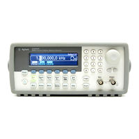
Agilent Technologies 33250A User Manual (337 pages)
80 MHz Function / Arbitrary Waveform Generator
Brand:
Agilent Technologies
| Category:
Inverter
| Size: 4.32 MB
Table of Contents
Convenient Bench-Top Features
2
Flexible System Features
2
The Front Panel at a Glance
3
The Front-Panel Display at a Glance
4
Front-Panel Number Entry
5
The Rear Panel at a Glance
6
In this Book
7
Table of Contents
9
Chapter 1 Quick Start
13
Quick Start
14
To Prepare the Function Generator for Use
15
Check the List of Supplied Items
15
Connect the Power Cord and Turn on the Function Generator
15
To Adjust the Carrying Handle
16
To Set the Output Frequency
17
To Set the Output Amplitude
18
To Set a DC Offset Voltage
20
To Set the Duty Cycle
21
To Configure a Pulse Waveform
22
To View a Waveform Graph
23
To Output a Stored Arbitrary Waveform
24
To Use the Built-In Help System
25
Local Language Help
26
To Rack Mount the Function Generator
27
Chapter 2 Front-Panel Menu Operation
29
Front-Panel Menu Reference
31
Configure the Modulation Parameters for AM, FM, and FSK
31
Configure the Parameters for Frequency Sweep
31
Configure the Parameters for Burst
31
Store and Recall Instrument States
32
Configure System-Related Parameters
32
View the List of Help Topics
32
To Select the Output Termination
33
To Reset the Function Generator
33
To Output a Modulated Waveform
34
To Output an FSK Waveform
36
To Output a Frequency Sweep
38
To Output a Burst Waveform
40
To Trigger a Sweep or Burst
42
To Store the Instrument State
43
To Configure the Remote Interface
44
GPIB Configuration
44
RS-232 Configuration
45
Features and Functions
47
Chapter 3 Features and Functions Output Configuration
49
Function Limitations
50
Amplitude Limitations
50
Front-Panel Operation
50
Remote Interface Operation
50
Output Frequency
51
Output Amplitude
52
DC Offset Voltage
54
Output Units
56
Output Termination
57
Duty Cycle
58
Symmetry
59
Voltage Autoranging
60
Output Control
60
Waveform Polarity
61
Sync Output Signal
62
Pulse Waveforms
64
Pulse Period
64
Pulse Width
65
Edge Time
66
Amplitude Modulation (AM)
67
Carrier Waveform Shape
68
Carrier Frequency
68
Modulating Waveform Shape
69
Modulating Waveform Frequency
69
Modulation Depth
70
Modulating Source
71
Frequency Modulation (FM)
72
Peak Frequency Deviation
76
Frequency-Shift Keying (FSK) Modulation
78
FSK Carrier Frequency
79
FSK “Hop” Frequency
80
FSK Rate
80
FSK Source
81
Frequency Sweep
82
Start Frequency and Stop Frequency
83
Center Frequency and Frequency Span
84
Sweep Mode
85
Sweep Time
85
Marker Frequency
86
Sweep Trigger Source
87
Trigger out Signal
88
Burst Mode
89
Burst Type
90
Waveform Frequency
92
Burst Count
93
Burst Period
94
Burst Phase
95
Burst Trigger Source
96
Triggering
98
Trigger Source Choices
98
Internal Triggering in the Internal Trigger Mode
99
Manual Triggering in the Manual Trigger Mode
99
External Triggering in the External Trigger Mode
100
Software (Bus) Triggering the Bus Trigger Mode
100
Trigger Input Signal
101
Trigger Output Signal
102
Arbitrary Waveforms
103
To Create and Store an Arbitrary Waveform
103
Select the Arbitrary Waveform Function
103
Start the Arbitrary Waveform Editor
103
Set the Waveform Period
104
Set the Waveform Voltage Limits
104
Select the Interpolation Method
104
Set the Initial Number of Waveform Points
105
Start the Point-By-Point Editing Process
105
Define the First Waveform Point
105
Define the Next Waveform Point
106
Define the Remaining Waveform Points
106
Store the Arbitrary Waveform in Memory
107
Additional Information on Arbitrary Waveforms
108
System-Related Operations
109
Instrument State Storage
109
Error Conditions
112
Beeper Control
113
Display Bulb-Saver
113
Display Contrast
114
Self-Test
114
Display Control
115
Number Format
116
Firmware Revision Query
117
SCPI Language Version Query
117
Remote Interface Configuration
118
GPIB Address
118
Remote Interface Selection
119
Baud Rate Selection (RS-232)
120
Parity Selection (RS-232)
120
Handshake Selection (RS-232)
121
Calibration Overview
123
Calibration Security
123
To Unsecure for Calibration
124
To Secure against Calibration
124
Calibration Count
125
To Change the Security Code
125
Calibration Message
126
Factory Default Settings
127
Remote Interface Reference
130
The Apply Commands
131
Chapter 4 Remote Interface Reference SCPI Command Summary
131
Output Configuration Commands
132
Pulse Configuration Commands
133
Modulation Commands
133
AM Commands
133
FM Commands
134
FSK Commands
134
Sweep Commands
135
Burst Commands
136
Arbitrary Waveform Commands
137
Triggering Commands
138
State Storage Commands
138
System-Related Commands
139
Interface Configuration Commands
139
Phase-Lock Commands
140
Status Reporting Commands
140
Calibration Commands
141
IEEE 488.2 Common Commands
141
Using the Apply Command
142
Using the Low-Level Commands
142
SCPI • Simplified Programming Overview
142
Reading a Query Response
143
Selecting a Trigger Source
143
Using the Apply Command
144
Apply Command Syntax
149
Output Configuration Commands (Low-Level Commands)
153
Pulse Configuration Commands (Remote Interface Reference)
166
AM Overview
169
Amplitude Modulation (AM) Commands
169
AM Commands Overview
170
FM Overview
172
Frequency Modulation (FM) Commands
172
FM Commands Overview
173
Frequency-Shift Keying (FSK) Commands
176
FSK Overview
176
FSK Commands Overview
177
Frequency Sweep Commands
179
Sweep Overview
179
Sweep Commands Overview
181
Burst Mode Commands
187
Burst Mode Overview
187
Burst Mode Commands Overview
189
Triggering Commands Overview
195
Arbitrary Waveform Commands/Arbitrary Waveform Overview
198
Using the IEEE-488.2 Binary Block Format
202
State Storage Commands Overview
209
System-Related Commands Overview
213
Interface Configuration Commands Overview
218
RS-232 Interface Configuration
219
RS-232 Handshake Methods
220
Connection to a Computer
221
RS-232 Data Frame Format
221
RS-232 Troubleshooting
222
Phase-Lock Commands Overview
223
The SCPI Status System
225
What Is a Condition Register?
225
What Is an Enable Register?
225
What Is an Event Register?
225
Agilent 33250A Status System
226
Bit Definitions – Status Byte Register
227
The Status Byte Register
227
Using Service Request (SRQ) and Serial Poll
229
Using STB? to Read the Status Byte
229
To Determine When a Command Sequence Is Completed
230
To Interrupt Your Computer Using SRQ
230
Using the Message Available Bit (MAV)
230
The Questionable Data Register
231
The Standard Event Register
233
Status Reporting Commands Overview
235
Questionable Data Register Commands
236
Standard Event Register Commands
237
Miscellaneous Status Register Commands
238
Calibration Commands Overview
239
SCPI • an Introduction to the SCPI Language
241
Command Format Used in this Manual
242
Command Separators
243
Using the MIN and MAX Parameters
243
IEEE-488.2 Common Commands
244
Querying Parameter Settings
244
SCPI Command Terminators
244
SCPI Parameter Types
245
Using Device Clear
246
Chapter 5 Error Messages
247
Error Messages
248
Command Errors
249
Execution Errors
252
Query Errors
267
Instrument Errors
268
Self-Test Errors
269
Calibration Errors
271
Arbitrary Waveform Errors
272
Chapter 6 Application Programs
275
Introduction
276
Example: BASIC for Windows
278
Example: Microsoft Visual Basic for Windows
282
Example: Microsoft Visual C++ for Windows
287
Tutorial
293
Chapter 7 Tutorial Direct Digital Synthesis
295
Creating Arbitrary Waveforms
298
Square Waveform Generation
300
Pulse Waveform Generation
300
Signal Imperfections
302
Harmonic Imperfections
302
Non-Harmonic Imperfections
302
Phase Noise
303
Quantization Errors Finite DAC Resolution (12 Bits)
303
Output Amplitude Control
304
Ground Loops
305
Attributes of AC Signals
307
Modulation
309
Frequency-Shift Keying (FSK)
312
Frequency Sweep
312
Sync and Marker Signals
314
Burst
315
Gated Burst in the Gated Burst Mode
317
Chapter 8 Specifications
319
Frequency Characteristics
320
Sinewave Spectral Purity
320
Signal Characteristics
320
Output Characteristics
321
Modulation Characteristics
321
Burst
321
Sweep
321
System Characteristics
322
Trigger Characteristics
322
Clock Reference
322
Sync Output
322
General Specifications
323
Product Dimensions
324
Index
325
Copyright Agilent Technologies, Inc
335
Declaration of Conformity
336
Advertisement
Agilent Technologies 33250A Service Manual (211 pages)
80 MHz Function / Arbitrary Waveform Generator
Brand:
Agilent Technologies
| Category:
Inverter
| Size: 6.45 MB
Table of Contents
Table of Contents
9
Chapter 1 Specifications
13
Chapter 2 Quick Start
19
To Prepare the Function Generator for Use
21
To Adjust the Carrying Handle
22
To Set the Output Frequency
23
To Set the Output Amplitude
24
To Set a DC Offset Voltage
26
To Set the Duty Cycle
27
To Configure a Pulse Waveform
28
To View a Waveform Graph
29
To Output a Stored Arbitrary Waveform
30
To Use the Built-In Help System
31
To Rack Mount the Function Generator
33
Chapter 3 Front-Panel Menu Operation
35
Front-Panel Menu Reference
37
To Reset the Function Generator
39
To Select the Output Termination
39
To Read the Calibration Information
40
To Unsecure and Secure for Calibration
41
To Store the Instrument State
44
To Configure the Remote Interface
45
Chapter 4 Calibration Procedures
47
Agilent Technologies Calibration Services
49
Calibration Interval
50
Adjustment Is Recommended
50
Time Required for Calibration
51
Automating Calibration Procedures
52
Recommended Test Equipment
53
Test Considerations
54
Performance Verification Tests
55
Internal Timebase Verification
60
AC Amplitude (High-Impedance) Verification
61
Low Frequency Flatness Verification
62
Chapter 4 Calibration Procedures (Continued)
62
Db Range Flatness Verification
63
Db Range Flatness Verification
65
Db Range Flatness Verification
66
Calibration Security
68
Calibration Message
70
Calibration Count
70
General Calibration/Adjustment Procedure
71
Aborting a Calibration in Progress
72
Sequence of Adjustments
72
Self-Test
73
Frequency (Internal Timebase) Adjustment
74
Internal ADC Adjustment
75
Output Impedance Adjustment
76
AC Amplitude (High-Impedance) Adjustment
78
Low Frequency Flatness Adjustment
80
Db Range Flatness Adjustments
81
Db Range Flatness Adjustments
83
+20 Db Range Flatness Adjustment
85
Pulse Width (Trailing Edge Delay) Adjustment
87
Pulse Edge Time Adjustment
88
Duty Cycle Adjustment
89
Output Amplifier Adjustment (Optional)
90
Calibration Errors
91
Chapter 5 Theory of Operation
93
Block Diagram
95
Main Power Supply
97
On-Board Power Supplies
98
Waveform DAC and Filters
100
Digital Waveform, Pulse, and Sync
101
Digital Waveform Translator
104
Amplitude Multiplier
106
Main Output Circuitry
107
System ADC
110
System DAC
112
Chapter 5 Theory of Operation (Continued)
112
Synthesis IC
113
Timebase
115
Phase Locked Loops
116
Clock Divider
118
Trigger and Delay
120
Waveform RAM
122
Synchronous Multiplexer
123
Main Processor
124
Main Gate Array
125
DSP and Gateway
126
Earth-Referenced Logic
126
Front Panel
127
Chapter 6 Service
129
Operating Checklist
130
Types of Service Available
131
Repackaging for Shipment
132
Cleaning
132
Electrostatic Discharge (ESD) Precautions
133
Surface Mount Repair
133
Troubleshooting Hints
134
Self-Test Procedures
136
Disassembly
140
Chapter 7 Replaceable Parts
151
33250-66511 Main PC Assembly (A1)
153
33205-66502 Front-Panel PC Assembly (A2)
176
33250A Chassis Assembly
177
33250A Front-Panel Assembly
178
Manufacturer's List
179
Chapter 8 Backdating
181
Chapter 9 Schematics
185
A1 Earth Referenced Communications Schematic
185
A1 Main Processor Schematic
186
A1 Main Gate Array Schematic
187
A1 Display Controller Schematic
188
A1 DSP Schematic
189
A1 Modulation Schematic
190
A1 System DAC Schematic
191
A1 Timebase Schematic
192
A1 Phase-Locked Loops Schematic
193
A1 Trigger Schematic
194
A1 Clock Divider and Control Schematic
195
A1 Synthesis IC Schematic
196
A1 Waveform Memory Schematic
197
A1 Synchronous Multiplexer Schematic
198
A1 Digital Waveform and Sync Schematic
199
A1 Variable-Edge Level Translation Schematic
200
A1 Waveform DAC, Filters, and Comparator Schematic
201
A1 Multiplier Schematic
202
A1 Main Output Circuitry Schematic
203
A1 Power Supply Schematic
204
A2 Keyboard Schematic
205
A2 Display Schematic
206
A1 Component Locator (Top)
207
A1 Component Locator (Bottom)
208
A2 Component Locator (Top)
209
A2 Component Locator (Bottom)
210
Copyright Agilent Technologies, Inc
211
Advertisement
Related Products
Agilent Technologies 33220A
Agilent Technologies 346A
Agilent Technologies 346B
Agilent Technologies 346C
Agilent Technologies 33120A
Agilent Technologies Agilent 33500 Series
Agilent Technologies 33210A
Agilent Technologies 339B
Agilent Technologies 33521A
Agilent Technologies 33522A
Agilent Technologies Categories
Measuring Instruments
Laboratory Equipment
Test Equipment
Water Pump
Power Supply
More Agilent Technologies Manuals
Login
Sign In
OR
Sign in with Facebook
Sign in with Google
Upload manual
Upload from disk
Upload from URL