Agilent Technologies 33120A Service Manual
15 mhz function/arbitrary waveform generator
Hide thumbs
Also See for 33120A:
- User manual (313 pages) ,
- Service manual (140 pages) ,
- Quick manual (12 pages)
Table of Contents
Advertisement
Service Guide
Publication Number 33120-90017 (order as 33120-90104 manual set)
Edition 6, March 2002
© Copyright Agilent Technologies, Inc. 1994-2002
For Safety information, Warranties, and Regulatory information,
see the last page in this manual.
Agilent 33120A
15 MHz Function /
Arbitrary Waveform Generator
Advertisement
Table of Contents

Related Manuals for Agilent Technologies 33120A


Summary of Contents for Agilent Technologies 33120A
- Page 1 Service Guide Publication Number 33120-90017 (order as 33120-90104 manual set) Edition 6, March 2002 © Copyright Agilent Technologies, Inc. 1994-2002 For Safety information, Warranties, and Regulatory information, see the last page in this manual. Agilent 33120A 15 MHz Function /...
- Page 3 Note: Unless otherwise indicated, this manual applies to all Serial Numbers. The Agilent Technologies 33120A is a high-performance 15 MHz synthesized function generator with built-in arbitrary waveform capability. Its combination of bench-top and system features makes this function generator a versatile solution for your testing requirements now and in the future.
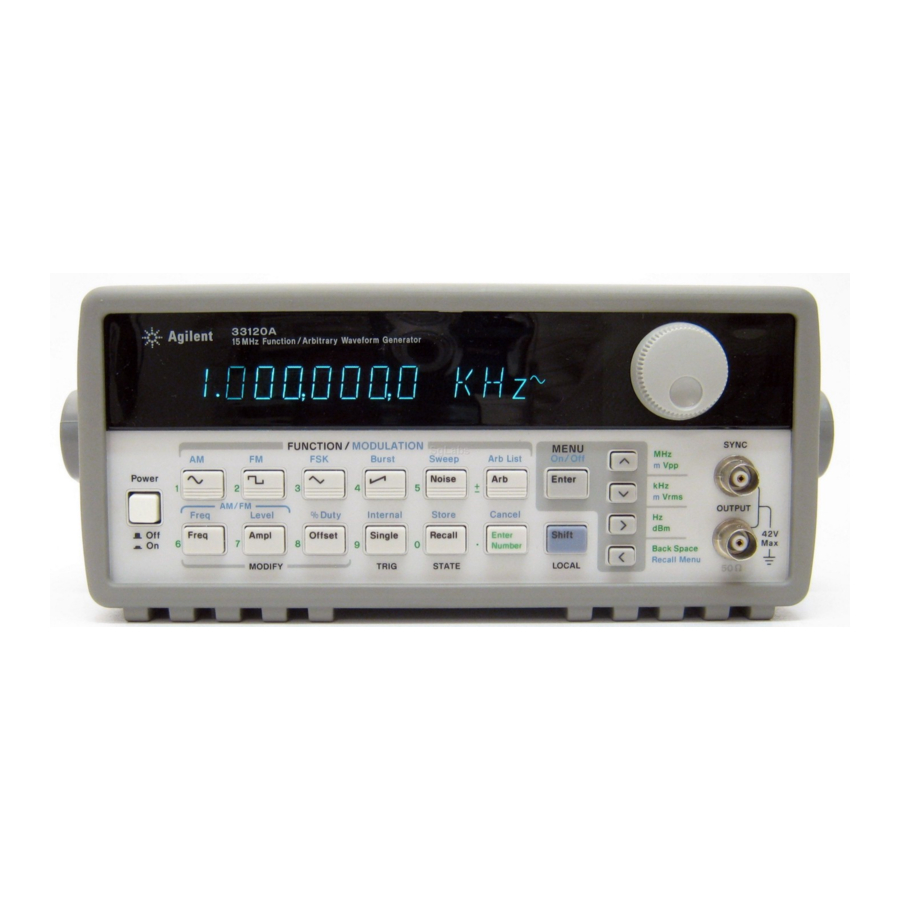
- Page 4 The Front Panel at a Glance 1 Function / Modulation keys 5 Recall / Store instrument state key 2 Menu operation keys 6 Enter Number key 3 Waveform modify keys 7 Shift / Local key 4 Single / Internal Trigger key 8 Enter Number “units”...
- Page 5 Front-Panel Number Entry You can enter numbers from the front-panel using one of three methods. Use the knob and the arrow keys to modify the displayed number. Use the arrow keys to edit individual digits. Increments the flashing digit. the flashing digit. Decrements Moves the flashing digit to the right...
- Page 6 The Front-Panel Menu at a Glance T he menu is organized in a top-down tree structure with three levels. A: MODulation MENU Õ Õ Õ Õ Õ 1: AM SHAPE 2: AM SOURCE 3: FM SHAPE 4: BURST CNT 5: BURST RATE Õ...
- Page 7 Display Annunciators Adrs Function generator is addressed to listen or talk over a remote interface. Function generator is in remote mode (remote interface). Trig Function generator is waiting for a single trigger or external trigger (Burst, Sweep). AM modulation is enabled. FM modulation is enabled.
- Page 8 The Rear Panel at a Glance 1 Chassis ground 5 External Trigger / FSK / Burst modulation input terminal 2 Power-line fuse-holder assembly 3 Power-line voltage setting 6 GPIB (IEEE-488) interface connector 4 AM modulation input terminal 7 RS-232 interface connector Use the front-panel Input / Output Menu to: œ...
- Page 9 Schematics Chapter 8 contains the function generator’s block diagram, schematics, disassembly drawings, and component locator drawings. For information on using the Phase-Lock Option for the 33120A, refer to the User’s and Service Guide included with the Option 001. If you have questions relating to the operation of the 33120A, call 1-800-452-4844 in the United States, or contact your nearest Agilent Technologies Sales Office.
-
Page 11: Table Of Contents
Contents Chapter 1 Specifications Chapter 2 Quick Start To prepare the function generator for use 21 If the function generator does not turn on 22 To adjust the carrying handle 24 To set the output frequency 25 To set the output amplitude 26 To set a dc offset voltage 27 To set the duty cycle 28 To output a stored arbitrary waveform 29... - Page 12 Contents Chapter 4 Calibration Procedures (continued) Calibration Security Code 64 Calibration Count 66 Calibration Message 66 General Calibration/Adjustment Procedure 67 Aborting a Calibration in Progress 69 Frequency and Burst Rate Adjustment 69 Function Gain and Linearity Adjustment 70 AC Amplitude Adjustment (High-Z) 70 Modulation Adjustment 72 AC Amplitude Adjustment (50 ) 73...
- Page 13 Troubleshooting Hints 108 Self-Test Procedures 110 Chapter 7 Replaceable Parts Replaceable Parts 113 Chapter 8 Schematics 33120A Block Diagram 129 Mechanical Disassembly 130 Floating Logic Schematic 131 Digital Waveform Data Synthesis 132 System DAC Schematic 133 Waveform DAC Schematic 134...
- Page 15 Specifications...
- Page 16 Chapter 1 Specifications Agilent 33120A Function Generator SIGNAL CHARACTERISTICS WAVEFORMS Squarewave Standard Waveforms: Sine, Square, Triangle, Rise/Fall Time: < 20 ns Ramp, Noise, DC volts, Overshoot: < 4% Sine(x)/x, Negative Ramp, Asymmetry: 1% + 5 ns Exponential Rise, Duty Cycle:...
- Page 17 Chapter 1 Specifications Agilent 33120A Function Generator SYSTEM CHARACTERISTICS MODULATION CHARACTERISTICS Configuration Times (2) AM Modulation Function Change: (3) Carrier -3 dB Freq: 10 MHz (typical) 80 ms Frequency Change: (3) Modulation: Any internal waveform plus Arb 30 ms 10 mHz to 20 kHz ( – 0.05% to...
- Page 18 Chapter 1 Specifications Agilent 33120A Function Generator GENERAL SPECIFICATIONS Power Supply: (1) 100V / 120V / 220V / 240V – Safety Designed to: EN61010, CSA1010, UL-1244 (switch selectable) EMC: EN61326, 1:1997 + 1A:1998 – Power-Line Frequency: 50 Hz to 60 Hz 10% and –...
- Page 19 Chapter 1 Specifications Agilent 33120A Function Generator PRODUCT DIMENSIONS All dimensions are shown in millimeters.
-
Page 21: Chapter 2 Quick Start
Quick Start... - Page 22 Quick Start One of the first things you will want to do with your function generator is to become acquainted with its front panel. We have written the exercises in this chapter to prepare the function generator for use and help you get familiar with some of the front-panel operations.
-
Page 23: To Prepare The Function Generator For Use
Chapter 2 Quick Start To prepare the function generator for use To prepare the function generator for use The following steps help you verify that the function generator is ready for use. 1 Check the list of supplied items. Verify that you have received the following items with your function generator. -
Page 24: If The Function Generator Does Not Turn On
Chapter 2 Quick Start If the function generator does not turn on If the function generator does not turn on Use the following steps to help solve problems you might experience when turning on the function generator. If you need more help, see chapter 6 for instructions on returning the function generator to Agilent for service. - Page 25 Chapter 2 Quick Start If the function generator does not turn on Remove the line-voltage selector from Remove the power cord . Remove the the assembly. fuse-holder assembly from the rear panel. Fuse: 500 mAT (for all line voltages) Part Number: 2110-0458 Rotate the line-voltage selector until the Replace the fuse-holder assembly in correct voltage appears in the window.
-
Page 26: To Adjust The Carrying Handle
Chapter 2 Quick Start To adjust the carrying handle To adjust the carrying handle To adjust the position, grasp the handle by the sides and pull outward. Then, rotate the handle to the desired position. Bench-top viewing positions Carrying position... -
Page 27: To Set The Output Frequency
Chapter 2 Quick Start To set the output frequency To set the output frequency At power-on, the function generator outputs a sine wave at 1 kHz with an amplitude of 100 mV peak-to-peak (into a 50 W termination). The following steps show you how to change the frequency to 1.2 MHz. 1 Enable the frequency modify mode. -
Page 28: To Set The Output Amplitude
Chapter 2 Quick Start To set the output amplitude To set the output amplitude At power-on, the function generator outputs a sine wave with an amplitude of 100 mV peak-to-peak (into a 50 W termination). The following steps show you how to change the amplitude to 50 mVrms. 1 Enable the amplitude modify mode. -
Page 29: To Set A Dc Offset Voltage
Chapter 2 Quick Start To set a dc offset voltage To set a dc offset voltage At power-on, the function generator outputs a sine wave with a dc offset voltage of 0 volts (into a 50 W termination). The following steps show you how to change the offset to –1.5 mVdc. -
Page 30: To Set The Duty Cycle
Chapter 2 Quick Start To set the duty cycle To set the duty cycle Applies only to square waves. At power-on, the duty cycle for square waves is 50%. You can adjust the duty cycle for a square waveform from 20% to 80%, in increments of 1% (for frequencies above 5 MHz, the range is 40% to 60%). -
Page 31: To Output A Stored Arbitrary Waveform
Chapter 2 Quick Start To output a stored arbitrary waveform To output a stored arbitrary waveform There are five built-in arbitrary waveforms stored in non-volatile memory for your use. You can output these waveforms directly from non-volatile memory. The following steps show you how to output an “exponential rise” waveform from memory. -
Page 32: To Output A Dc Voltage
Chapter 2 Quick Start To output a dc voltage To output a dc voltage In addition to generating waveforms, you can also output a dc voltage in the range – 5 Vdc (into a 50 W termination). The following steps show you how to output +155 mVdc. -
Page 33: To Store The Instrument State
Chapter 2 Quick Start To store the instrument state To store the instrument state You can store up to three different instrument states in non-volatile memory. This enables you to recall the entire instrument configuration with just a few key presses from the front panel. The following steps show you how to store and recall a state. - Page 34 Chapter 2 Quick Start To store the instrument state To verify that the state was stored properly, you can turn the power off before recalling the state. 5 Recall the stored instrument state. Recall To recall the stored state, you must use the same memory location used previously to store the state.
-
Page 35: To Rack Mount The Function Generator
Any Agilent System II instrument of the same size can be rack-mounted beside the 33120A Function Generator. Remove the carrying handle, and the front and rear rubber bumpers, before rack-mounting the function generator. - Page 36 Chapter 2 Quick Start To rack mount the function generator To rack mount a single instrument, order adapter kit 5063-9240. To rack mount two instruments side-by-side, order lock-link kit 5061-9694 and flange kit 5063-9212. To install one or two instruments in a sliding support shelf, order shelf 5063-9255, and slide kit 1494-0015 (for a single instrument, also order filler panel 5002-3999).
-
Page 37: Chapter 3 Front-Panel Menu Operation
Front-Panel Menu Operation... - Page 38 See chapter 3 “Features and Functions” in the User’s Guide for a complete discussion of the function generator’s capabilities and operation. If you purchased the Phase-Lock Option for the 33120A, an additional menu is available from the front panel. For inform- (G: PHASE MENU) ation on using the Phase-Lock Option, refer to the User’s and Service...
-
Page 39: Front-Panel Menu Reference
Chapter 3 Front-Panel Menu Operation Front-panel menu reference Front-panel menu reference A: MODulation MENU Õ Õ Õ Õ Õ 1: AM SHAPE 2: AM SOURCE 3: FM SHAPE 4: BURST CNT 5: BURST RATE Õ Õ Õ Õ Õ 6: BURST PHAS 7: BURST SRC 8: FSK FREQ 9: FSK RATE... - Page 40 Chapter 3 Front-Panel Menu Operation Front-panel menu reference D: SYStem MENU Õ Õ Õ Õ Õ 1: OUT TERM 2: POWER ON 3: ERROR 4: TEST 5: COMMA 6:REVISION 1: OUT TERM Selects the output termination (50 or high impedance). 2: POWER ON Enables or disables automatic power-up in power-down state “0”.
-
Page 41: A Front-Panel Menu Tutorial
Chapter 3 Front-Panel Menu Operation A front-panel menu tutorial A front-panel menu tutorial This section is a step-by-step tutorial which shows you how to use the front-panel menu. We recommend that you spend a few minutes with this tutorial to get comfortable with the structure and operation of the menu before attempting verification, calibration, or adjustments. - Page 42 Chapter 3 Front-Panel Menu Operation A front-panel menu tutorial Messages Displayed During Menu Use ¾ TOP OF MENU You pressed while on the “ ” level; this is the top MENUS level of the menu and you cannot go any higher. To turn off the menu, press .
- Page 43 Chapter 3 Front-Panel Menu Operation A front-panel menu tutorial Menu Example 1 The following steps show you how to turn on the menu, move up and down between levels, move across the choices on each level, and turn off the menu. In this example, you will restore the function generator to the power-on default state.
- Page 44 Chapter 3 Front-Panel Menu Operation A front-panel menu tutorial 5 Move down a level to the “ ” choices. PARAMETER ¿ The first parameter choice is “ ” for the command DEFAULT POWER ON (“ ” is the factory setting and is stored in non-volatile memory). DEFAULT DEFAULT 6 Move across to the...
- Page 45 Chapter 3 Front-Panel Menu Operation A front-panel menu tutorial Menu Example 2 Some commands in the menu require that you enter a numeric parameter value. The following steps show you how to enter a number in the menu. For this example, you will change the output amplitude. 1 Select amplitude adjustment Ampl The function generator displays the current output amplitude.
-
Page 46: To Select The Output Termination
Chapter 3 Front-Panel Menu Operation To select the output termination To select the output termination The function generator has a fixed output impedance of 50 ohms on the OUTPUT terminal. You can specify whether you are terminating the output into a 50 load or an open circuit. -
Page 47: To Output A Modulated Waveform
Chapter 3 Front-Panel Menu Operation To output a modulated waveform To output a modulated waveform A modulated waveform consists of a carrier and a modulating waveform. (amplitude modulation), the amplitude of the carrier is varied by the amplitude of the modulating waveform. For this example, you will output an AM waveform with 80% modulation depth. - Page 48 Chapter 3 Front-Panel Menu Operation To output a modulated waveform 4 Move down a level verify that “ ” is selected. SINE ¿ For the modulating waveform, you can select a sine, square, triangle, ramp, noise, or arbitrary waveform. For this example, you will modulate the carrier with a sine waveform.
-
Page 49: To Unsecure The Function Generator For Calibration
Chapter 3 Front-Panel Menu Operation To unsecure the function generator for calibration To unsecure the function generator for calibration The function generator can use a calibration security code to prevent unauthorized or accidental calibration. This procedure shows you how to unsecure the function generator for calibration. - Page 50 Chapter 3 Front-Panel Menu Operation To unsecure the function generator for calibration 4 Move down to the “parameters” level. ¿ ^000000:CODE 5 Unsecure the function generator by entering the security code. ^033120:CODE ENTER The security code is set to “HP33120” when the function generator is shipped from the factory.
-
Page 51: Chapter 4 Calibration Procedures
Calibration Procedures... - Page 52 Calibration Procedures This chapter contains procedures for verification of the function generator’s performance and adjustment (calibration). The chapter is divided into the following sections: œ Agilent Calibration Services ....51 œ...
-
Page 53: Agilent Calibration Services
Whatever calibration interval you select, Agilent recommends that complete re-adjustment should always be performed at the calibration interval. This will increase your confidence that the 33120A will remain within specification for the next calibration interval. This criteria for re-adjustment provides the best long-term stability. Performance data measured using this method can be used to extend future calibration intervals. -
Page 54: Automating Calibration Procedures
For further detailing on programming the function generator, see chapters 3 and 4 in the Agilent 33120A User’s Guide. Recommended Test Equipment The test equipment recommended for the performance verification and adjustment procedures is listed below. -
Page 55: Test Considerations
Chapter 4 Calibration Procedures Test Considerations Test Considerations To ensure proper instrument operation, verify that you have selected the correct power line voltage prior to attempting any test procedure in this chapter. See page 22 in chapter 2 for more information. For optimum performance, all test procedures should comply with the following recommendations: œ... -
Page 56: Performance Verification Tests
. You can also perform a self-test from TEST SYS MENU the remote interface (see chapter 3 in the Agilent 33120A User’s Guide). œ If the self-test is successful, “ ” is displayed on the front panel. PASS œ... - Page 57 Chapter 4 Calibration Procedures Performance Verification Tests Quick Performance Check The quick performance check is a combination of internal self-test and an abbreviated performance test (specified by the letter Q in the performance verification tests). This test provides a simple method to achieve high confidence in the function generator’s ability to functionally operate and meet specifications.
-
Page 58: Frequency Verification
Set the function generator for each output indicated in the table below. Use a frequency meter to measure the output frequency. Compare the measured results to the test limits shown in the table. This is a 50 output termination test. Agilent 33120A Measurement BURST BURST... -
Page 59: Dc Function Offset Verification
Set the function generator for each output indicated in the table below. Use a DMM to measure the function generator dcV output. Compare the measured results to the test limits shown in the table. This is a HIGH Z output termination test. Agilent 33120A Measurement Function OUT TERM... - Page 60 Chapter 4 Calibration Procedures AC Amplitude Verification Agilent 33120A Measurement Function OUT TERM Ampl Freq Nominal Error – 0.070 Vrms Sine wave HIGH Z 7.0 Vrms 1.00 kHz 7.0 Vrms – 0.057 Vrms Sine wave HIGH Z 5.7 Vrms 1.00 kHz 5.7 Vrms...
- Page 61 Use a DMM to measure the ACrms output voltage of the function generator. Compare the measured results to the test limits shown in the table. This is a 50 output termination test. Agilent 33120A Measurement Function OUT TERM...
-
Page 62: Amplitude Flatness Verification
Compare the amplitude level set on the front panel to the test limits shown in the table. This test is a 50 output termination test. Agilent 33120A Measurement Function Ampl Freq... -
Page 63: Am Modulation Depth Verification
Select each function generator output in the table below. Use a DMM to measure the function generator ACrms output voltage. Compare the measured results to the test limits shown in the table. This is a HIGH Z output termination test. Agilent 33120A Measurement AM Modulation Function... -
Page 64: Optional Performance Verification Tests
Select each function generator output in the table below. Use an integrating DMM to measure the Vdc output of the function generator. Compare the measured results to the test limits shown in the table. This is a HIGH Z output termination test. Agilent 33120A Measurement Duty Function... - Page 65 Set the fundamental frequency reference to 0 dB and measure the 2nd through 5th harmonic frequencies relative to this reference. This test is a 50 W output termination test. Agilent 33120A Measurement harmonic Value below...
-
Page 66: Calibration Security Code
Chapter 4 Calibration Procedures Calibration Security Code Calibration Security Code This feature allows you to enter a security code (electronic key) to prevent accidental or unauthorized calibrations of the function generator. When you first receive your function generator, it is secured. Before you can adjust calibration constants you must unsecure the function generator by entering the correct security code. - Page 67 Chapter 4 Calibration Procedures Calibration Security Code To Unsecure the Function Generator Without the Security Code To unsecure the function generator without the correct security code, follow the steps below. A procedure to unsecure the function generator is given on page 47. Also see “Electrostatic Discharge (ESD) Precautions” in chapter 6 before beginning this procedure.
-
Page 68: Calibration Count
Chapter 4 Calibration Procedures Calibration Count Calibration Count The calibration count feature provides an independent “serialization” of your calibrations. You can determine the number of times that your function generator has been calibrated. By monitoring the calibration count, you can determine whether an unauthorized calibration has been performed. -
Page 69: General Calibration/Adjustment Procedure
Chapter 4 Calibration Procedures General Calibration/Adjustment Procedure General Calibration/Adjustment Procedure The adjustment procedures described in chapter 4 use the CAL MENU to generate and set internal calibration constants. The general menu procedure is the same for all calibration setups. The following example demonstrates making the Frequency and Burst Rate adjustments. - Page 70 Chapter 4 Calibration Procedures General Calibration/Adjustment Procedure 7 Move the flashing cursor over the digit to be edited. < > 8 Change the value in the display to match the measured frequency. ¿ 1.000,0040KHz 9 Calculate and save the new value. Enter CALIBRATING 10 Perform the next adjustment procedure.
-
Page 71: Aborting A Calibration In Progress
Chapter 4 Calibration Procedures Aborting a Calibration in Progress Aborting a Calibration in Progress Sometimes it may be necessary to abort a calibration after the procedure has already been initiated. You can abort a calibration at any time by pressing any front-panel key (except ). -
Page 72: Function Gain And Linearity Adjustment
Chapter 4 Calibration Procedures Function Gain and Linearity Adjustment Function Gain and Linearity Adjustment The function generator stores six calibration constants related to function gain and linearity. The constants are calculated from the adjustment value entered. If the calibration procedure is aborted before all setup steps have been completed, no calibration constants are stored. - Page 73 Chapter 4 Calibration Procedures AC Amplitude Adjustment (High-Z) Nominal Output SETUP FREQUENCY AMPLITUDE Adjustment for: 1 kHz 5.5 V rms 2 dB Output Attenuator 1 kHz 4.4 V rms 4 dB Output Attenuator 1 kHz 3.5 V rms 6 dB Output Attenuator 1 kHz 2.8 V rms 8 dB Output Attenuator...
-
Page 74: Modulation Adjustment
Chapter 4 Calibration Procedures Modulation Adjustment Modulation Adjustment The function generator stores three calibration constants related to amplitude modulation depth. The constants are calculated from the adjustment value entered. If the calibration procedure is aborted before all setup steps have been completed, no calibration constants are stored. 1 Use a DMM to measure the function generator ACrms output voltage for each setup in the following table. - Page 75 Chapter 4 Calibration Procedures AC Amplitude Adjustment (50 AC Amplitude Adjustment (50 1 The function generator stores 16 calibration constants related to 50 output. The constants are calculated from the adjustment value entered. The calibration constants are stored following completion of setup 49 and the calibration procedure may be aborted after that point.
-
Page 76: Ac Amplitude Adjustment (50 W )
Chapter 4 Calibration Procedures AC Amplitude Adjustment (50 4 Use the DMM to measure the function generator ACrms output voltage for each setup in the table on the next page. These adjustments use the 50 W load and cable measured in step 2 and connected as shown below. - Page 77 Chapter 4 Calibration Procedures AC Amplitude Adjustment (50 Nominal Output SETUP FREQUENCY AMPLITUDE Adjustment for: 1 kHz 3.5 Vrms 0 dB Output Attenuator 1 kHz 2.8 Vrms 2 dB Output Attenuator 1 kHz 2.23 Vrms 4 dB Output Attenuator 1 kHz 1.77 Vrms 6 dB Output Attenuator 1 kHz...
-
Page 78: Dc Output Adjustment
Chapter 4 Calibration Procedures DC Output Adjustment DC Output Adjustment The function generator stores nine calibration constants related to DC volts output. The constants are calculated from the adjustment value entered. The calibration constants are stored following completion of setup 59. No calibration constants are stored if the procedures are aborted at any other setup. -
Page 79: Duty Cycle Adjustment
Chapter 4 Calibration Procedures Duty Cycle Adjustment Duty Cycle Adjustment The function generator stores two calibration constants related to squarewave offset and two calibration constants related to squarewave duty cycle. The constants are calculated from the adjustment value entered. The calibration constants are stored following completion of setup 63. - Page 80 Chapter 4 Calibration Procedures AC Amplitude Flatness Adjustment This procedure can be performed with one of three types of measurement device; a broadband ACrms voltmeter, a power meter, or a thermal voltage converter. The procedure differs slightly depending upon the type of measurement device used.
- Page 81 Chapter 4 Calibration Procedures AC Amplitude Flatness Adjustment 3 For each setup in the table below, use the CALIBRATE command to change the displayed amplitude to match the measured amplitude. Nominal Output SETUP FREQUENCY AMPLITUDE Adjustment for: 100 kHz 3.0 V rms 100 kHz amplitude flatness 500 kHz 3.0 V rms...
-
Page 82: Output Amplifier Adjustment (Optional)
Chapter 4 Calibration Procedures Output Amplifier Adjustment (Optional) Output Amplifier Adjustment (Optional) This adjustment procedure should only be performed following repairs to the Output Amplifier circuitry. The adjustment improves the high frequency performance of the Output Amplifier. 1 Remove the function generator power and cover as described on page 130. 2 Use a DMM to measure the ACrms voltage across J701 as shown below. -
Page 83: Error Messages
They are intended to include errors which are likely to be encountered during the procedures described in this chapter. For a more complete list of error messages and descriptions, see chapter 5 in the Agilent 33120A User’s Guide. System Error Messages Error... - Page 84 Chapter 4 Calibration Procedures Error Messages Calibration Error Messages Error Error Message Cal security disabled by jumper Cal secured Invalid secure code Secure code too long Cal aborted Cal value out of range Cal signal measurement out of range Flatness cal failed Cannot calibrate frequency while externally locked (Option 001) RAM checksum failure Cal setup invalid...
-
Page 85: Chapter 5 Theory Of Operation
Theory of Operation... - Page 86 Theory of Operation This chapter is organized to provide descriptions of the circuitry contained on the schematics shown in chapter 8. A block diagram overview is provided followed by more detailed descriptions of the circuitry contained in the schematics chapter. œ...
-
Page 87: Block Diagram Overview
Chapter 5 Theory of Operation Block Diagram Overview Block Diagram Overview This discussion pertains to the block diagram shown on page 129. The function function generator’s circuitry is divided into two major blocks: the floating section and the earth (ground) reference section. All signal generation, control, and display functions are contained in the floating section. -
Page 88: Output Attenuator
Chapter 5 Theory of Operation Output Attenuator Output Attenuator Block 8 on block diagram page 129; Schematic on page 138. The Output Attenuator provides 0 to 30 dB of signal attenuation between the output amplifier section and the output BNC connector. Output signal levels are controlled by combining coarse amplitude control from the output attenuator section and pre-attenuator section with fine amplitude control from the Waveform DAC AMP_CTL signal. -
Page 89: Output Amplifier
Chapter 5 Theory of Operation Output Amplifier Output Amplifier Block 7 on block diagram page 129; Schematic on page 137. The output amplifier drives the function generator’s signal output through the output attenuator section. The output amplifier exhibits an approximate 35 MHz bandwidth and 1000 V/ m s slew rate. AC signals originating from the DAC+ and DAC- signal paths are combined at the input of the amplifier. - Page 90 Chapter 5 Theory of Operation Output Amplifier The block diagram shows four basic stages: dc amplifier, input differential amplifier, gain, and power output. The amplifier’s input differential amplifier stage and gain stage are symmetrical. The +AMP_IN and -AMP_IN inputs are both amplified through complementary amplifiers whose outputs are summed together at the input of the power output stage.
-
Page 91: Am Modulation
Chapter 5 Theory of Operation AM Modulation AM Modulation Blocks 3 and 6 on block diagram page 129; Schematics on pages 136 and 133. Amplitude modulation is performed by analog multiplier U603 combining the AM_IN and +FUNCTION and -FUNCTION signals. Modulation depths from 0% to 120% are set by varying the signal at AM_IN. -
Page 92: Pre-Attenuator
Chapter 5 Theory of Operation Pre-attenuator Pre-attenuator Block 6 on block diagram page 129; Schematic on page 136. All signals, except square waves, pass through the preattenuator. The preattenuator multiplexes eight resistive 2 dB attenuators to provide attenuation from 0 dB to 14 dB in 2 dB steps. The 0 dB, 2 dB, and 4 dB attenuation steps are used for level settings between the 6 dB steps selected in the output attenuator section. - Page 93 Chapter 5 Theory of Operation Square Wave and Sync Transistors Q601 and Q602 buffer the output of the sine wave anti-alias filter to the input of comparator U620. Square wave duty cycles are controlled by the SQ_SYM input on the inverting input of the comparator. The squarewave outputs of U620 are amplified by variable gain amplifiers Q603 and Q604.
-
Page 94: Filters
Chapter 5 Theory of Operation Filters Filters Block 5 on block diagram page 129; Schematic on page 135. The output of the Waveform DAC passes through one of two anti-alias filters. A 17 MHz 9th order elliptical filter is used for the sine wave and square wave output functions. -
Page 95: Waveform Dac/Amplitude Leveling/Waveform Ram
Chapter 5 Theory of Operation Waveform DAC/Amplitude Leveling/Waveform RAM Waveform DAC/Amplitude Leveling/Waveform RAM Block 4 on block diagram page 129; Schematic on page 134. The Waveform DAC, U407, converts 12-bit digital data from waveform RAM’s U404 and U405 into positive and negative analog voltages. A simplified diagram of the Waveform DAC circuitry is shown below. - Page 96 Chapter 5 Theory of Operation Waveform DAC/Amplitude Leveling/Waveform RAM The Waveform DAC voltage reference is driven by U410B. This reference controls the magnitude of the nominal 0 to -40 mA DAC output current. The reference level is varied to produce 0 to -2 dB fine amplitude level –...
-
Page 97: Direct Digital Synthesis (Dds Asic)
Chapter 5 Theory of Operation Direct Digital Synthesis (DDS ASIC) Direct Digital Synthesis (DDS ASIC) Block 2 on block diagram page 129; Schematic on page 132. The DDS ASIC, U206, controls the WA (waveform address) and MA (modulation address) busses. The waveform address is used by the waveform RAMs U404 and U405. -
Page 98: System Dacs
Chapter 5 Theory of Operation System DACs System DACs Block 3 on block diagram page 129; Schematic on page 133. All output amplitudes are derived from the internal voltage reference of System DAC U303. The system dac track/hold amplifier outputs are used to provide controllable bias voltages to various analog circuits including AM modulation depth, square wave amplitude, square wave duty cycle, output dc offset, and output amplitude level. -
Page 99: Floating Logic
Chapter 5 Theory of Operation Floating Logic Floating Logic Block 1 on block diagram page 129; Schematic on page 131. The floating logic controls the operation of the entire function function generator. All output functions and bus command interpretation is performed by the main CPU, U102. -
Page 100: Earth-Referenced Logic
Chapter 5 Theory of Operation Earth-Referenced Logic The main CPU, U102, communicates with the earth referenced logic through an optically isolated asynchronous serial data link. U101 isolates the incoming data (OG_RXD*) from the earth referenced logic. Similarly, U901 isolates the data from U102 (OG_TXD) to the earth reference logic. Data is sent in an 11-bit frame at a rate of 187.5 k bits/second. - Page 101 Chapter 5 Theory of Operation Power Supplies The ac mains are connected by a fused power entry module, P1. This module incorporates the functions of mains connection, on/off switching, fusing, and line voltage selection (100/120/220 (230)/240). The line voltage selection function of module P1 selects which primary winding of power transformer T1 is energized.
-
Page 102: Display And Keyboard
Chapter 5 Theory of Operation Display and Keyboard Display and Keyboard Block 11 on block diagram page 129; Schematic on page 141. The front panel circuits consist of vacuum fluorescent display control, display high voltage drivers, and keyboard scanning. Communication between the front panel and floating logic circuits is accomplished through a 4-wire bi-directional serial interface. -
Page 103: Chapter 6 Service
Service... - Page 104 Service This chapter discusses the procedures involved for returning a failed function generator to Agilent for service or repair. Subjects covered include the following: œ Operating Checklist ....103 œ...
-
Page 105: Operating Checklist
Chapter 6 Service Operating Checklist Operating Checklist Before returning your function generator to Agilent for service or repair, check the following items: Is the function generator inoperative? Verify that the ac power cord is connected to the function generator. Verify that the front-panel Power switch is depressed. Verify that the power-line fuse is good (see page 22). -
Page 106: Types Of Service Available
œ If you do not return your failed unit within 15 business days, your credit card will be billed for the cost of a new 33120A. 2 Agilent will immediately send a replacement 33120A directly to you. -
Page 107: Repackaging For Shipment
Chapter 6 Service Repackaging for Shipment Repackaging for Shipment If the unit is to be shipped to Agilent for service or repair, be sure to: œ Attach a tag to the unit identifying the owner and indicating the required service or repair. Include the instrument model number and your full serial number. -
Page 108: Electrostatic Discharge (Esd) Precautions
Chapter 6 Service Electrostatic Discharge (ESD) Precautions Electrostatic Discharge (ESD) Precautions Almost all electrical components can be damaged by electrostatic discharge ( ) during handling. Component damage can occur at electrostatic discharge voltages as low as 50 volts. The following guidelines will help prevent damage when servicing the function generator or any electronic device. -
Page 109: To Replace The Power-Line Fuse
Chapter 6 Service To Replace the Power-Line Fuse To Replace the Power-Line Fuse The power-line fuse is located within the function generator’s fuse-holder assembly on the rear panel (see page 22). The function generator is shipped from the factory with a 500 mAT slow-blow fuse installed (part number 2110-0458). -
Page 110: Troubleshooting Hints
Chapter 6 Service Troubleshooting Hints Troubleshooting Hints This section provides a brief checklist of common failures. Before trouble- shooting or repairing the function generator, make sure the failure is in the instrument rather than any external connections. Also make sure that the instrument is accurately calibrated. - Page 111 Chapter 6 Service Troubleshooting Hints Power Supply Problems SHOCK HAZARD. Only service-trained personnel who are aware W A R N I N G of the hazards involved should remove the instrument covers. The procedures in this section require that you connect the power cord to the instrument with the covers removed.
-
Page 112: Self-Test Procedures
Chapter 6 Service Self-Test Procedures Self-Test Procedures Power-On Self-Test Each time the function generator is powered on, a small set of self-tests are performed. These tests check that the minimum set of logic and measurement hardware are functioning properly. The power-on self-test performs checks 601, 625, and 626. - Page 113 Chapter 6 Service Self-Test Procedures Serial configuration readback failed This test re-sends the last 3 byte serial configuration data to all the serial path (SERDAT, SERBCK, SERCLK). The data is then clocked back into U103 and compared against the original 3 bytes sent. A failure occurs if the data do not match. This tests checks the serial data path through U301, U302, and U305.
-
Page 115: Replaceable Parts
Replaceable Parts... - Page 116 Replaceable Parts This chapter contains information to help you order replacement parts for your 33120A Function Generator. The parts lists are divided into the following groups: œ 33120-66521 Main PC Assembly (A1) œ 33120-66502 Front-Panel Display and Keyboard PC Assembly (A2) œ...
- Page 117 Chapter 7 Replaceable Parts 33120-66521 – Main PC Assembly 33120-66521 – Main PC Assembly Reference Agilent Part Mfr. Mfr. Part Designator Number Part Description Code Number C101-C102 0160-6497 CAP-FXD 0.1 uF 25 V 04222 12065C104KAT A C103-C105 0160-5945 CAP-FXD 0.01 uF 50 V 04222 08055C103KAT A C107 0160-5945...
- Page 118 Chapter 7 Replaceable Parts 33120-66521 – Main PC Assembly Reference Agilent Part Mfr. Mfr. Part Designator Number Part Description Code Number C535-C536 0160-5952 CAP-FXD 330 pF 50 V 04222 08055A331JAT A C539-C540 0160-7721 CAP-FXD 82 pF +-1% 50 V CER C0G 04222 08055A820FATMA C541-C542 0160-5965...
- Page 119 Chapter 7 Replaceable Parts 33120-66521 – Main PC Assembly Reference Agilent Part Mfr. Mfr. Part Designator Number Part Description Code Number C1017-1019 0160-5947 CAP-FXD 1000 pF 50 V 04222 08055C102KAT A C1020-1021 0160-5945 CAP-FXD 0.01 uF 50 V 04222 08055C103KAT A C1051-C1052 0160-6497 CAP-FXD 0.1 uF 25 V...
- Page 120 Chapter 7 Replaceable Parts 33120-66521 – Main PC Assembly Reference Agilent Part Mfr. Mfr. Part Designator Number Part Description Code Number JM1001-1004 0699-1503 RESISTOR .05 +-100% TKF 28480 0699-1503 JM1051 0699-1503 RESISTOR .05 +-100% TKF 28480 0699-1503 K501-K502 0490-1664 RELAY 2C 5VDC-COIL 1A 110VDC 28480 0490-1664 K601-K602 0490-1664...
- Page 121 Chapter 7 Replaceable Parts 33120-66521 – Main PC Assembly Reference Agilent Part Mfr. Mfr. Part Designator Number Part Description Code Number R301 0699-1403 RESISTOR 31.6K +-1% .125 W TKF TC=0+-100 28480 0699-1403 R302 0699-3211 RESISTOR 39.2K 1% 1206 .125 W 200V TC=100 28480 0699-3211 R303-R304 0699-1318...
- Page 122 Chapter 7 Replaceable Parts 33120-66521 – Main PC Assembly Reference Agilent Part Mfr. Mfr. Part Designator Number Part Description Code Number R629 0699-2712 RESISTOR 255 +-1% .125 W TKF TC=0+-100 28480 0699-2712 R630 0699-1415 RESISTOR 100 +-1% .125 W TKF TC=0+-10 28480 0699-1415 R631 0699-1432...
- Page 123 Chapter 7 Replaceable Parts 33120-66521 – Main PC Assembly Reference Agilent Part Mfr. Mfr. Part Designator Number Part Description Code Number R724 0699-1437 RESISTOR 825 +-1% .125 W TKF TC=0+-100 28480 0699-1437 R725 0699-1415 RESISTOR 100 +-1% .125 W TKF TC=0+-100 28480 0699-1415 R726-R727 0699-2064...
- Page 124 Chapter 7 Replaceable Parts 33120-66521 – Main PC Assembly Reference Agilent Part Mfr. Mfr. Part Designator Number Part Description Code Number R908 0699-1318 RESISTOR 1K +-1% .125 W TKF TC=0+-100 28480 0699-1318 R909 0699-3408 RESISTOR 1K +-5% 1 W TKF TC=0+-200 2M627 MCR1001KJ R910 0699-1391...
- Page 125 Chapter 7 Replaceable Parts 33120-66521 – Main PC Assembly Reference Agilent Part Mfr. Mfr. Part Designator Number Part Description Code Number U301-U302 1821-0964 IC DRVR 8X S 20SOL 45V 250MA 01295 TPIC6595DW U303 1826-2793 IC DA VOUT SER 16SOL 16BIT AD1851R 24355 AD1851R U304 1821-0434...
- Page 126 Chapter 7 Replaceable Parts 33120-66502 – Display and Keyboard PC Assembly 33120-66502 – Display and Keyboard PC Assembly Reference Agilent Part Mfr. Mfr. Part Designator Number Part Description Code Number C1101 0160-5945 CAP-FXD 0.01 uF 50 V 04222 08055C103KAT A C1102-1103 0180-3751 CAP-FXD 1 uF 35 V TA...
- Page 127 Chapter 7 Replaceable Parts 33120A Mainframe 33120A Mainframe Reference Agilent Part Mfr. Mfr. Part Designator Number Part Description Code Number 33120-66521 MAIN PC ASSEMBLY 28480 33120-66521 33120-66502 DISPLAY AND KEYBOARD PC ASSEMBLY 28480 33120-66502 3160-0847 FAN-TBAX 12V 5.3-CFM NOM 11855 DFB0412L-SG...
- Page 128 27014 National Semiconductor Corp Santa Clara, CA, U.S.A. 95052 27264 Molex Inc Lisle, IL, U.S.A. 60532 28480 Agilent Technologies, Inc. Palo Alto, CA, U.S.A. 94303 32997 Bourns Networks Inc Riverside, CA, U.S.A. 92507 34335 Advanced Micro Devices Inc Sunnyvale, CA, U.S.A.
-
Page 129: Chapter 8 Schematics
Schematics... - Page 130 Schematics œ 33120A Block Diagram ....129 œ Mechanical Disasembly ....130 œ...
-
Page 131: 33120A Block Diagram
Block Diagram... -
Page 132: Mechanical Disassembly
Loosen Pull Off Handle Captive Slide Off Outer Case Pull Off Bumpers Screws Remove Bottom Screw Pull To Remove Pry Outward From This Side Press Down To Unlatch Cable Pull Up To Disconnect Remove Screw Front Panel Will Pull Off Mechanical Disassembly... -
Page 133: Floating Logic Schematic
33120-66521 (sheet 1 of 10) Floating Logic Schematic... -
Page 134: Digital Waveform Data Synthesis
33120-66521 (sheet 2 of 10) Digital Waveform Data Synthesis Schematic... -
Page 135: System Dac Schematic
33120-66521 (sheet 3 of 10) System DAC Schematic... -
Page 136: Waveform Dac Schematic
33120-66521 (sheet 4 of 10) Waveform DAC Schematic... -
Page 137: Filters Schematic
33120-66521 (sheet 5 of 10) Filters Schematic... -
Page 138: Sync, Square Wave, And Attenuator Schematic
33120-66521 (sheet 6 of 10) Sync, Square Wave, and Attenuator Schematic... -
Page 139: Output Amplifier Schematic
33120-66521 (sheet 7 of 10) Output Amplifier Schematic... -
Page 140: Output Attenuator Schematic
33120-66521 (sheet 8 of 10) Output Attenuator Schematic... -
Page 141: Earth Reference Logic Schematic
33120-66521 (sheet 9 of 10) Earth Reference Logic Schematic... -
Page 142: Power Supplies Schematic
33120-66521 (sheet 10 of 10) Power Supplies Schematic... -
Page 143: Display And Keyboard Schematic
33120-66502 (sheet 1 of 1) Display and Keyboard Schematic... -
Page 144: 33120-66521 Component Locator Diagram
TOP SIDE 33120-66521 REV A 33120-66521 Component Locator Diagram... -
Page 145: 33120-66502 Component Locator Diagram
TOP SIDE 33120-66502 REV C 33120-66502 Component Locator Diagram... - Page 146 Copyright Agilent Technologies, Inc. Warranty Safety Notices 1994-2002 The material contained in this Do not install substitute parts or document is provided “as is,” and perform any unauthorized modifica- No part of this manual may be repro- is subject to being changed, with- tion to the product.