Table of Contents
Advertisement
Quick Links
Installation Guide
Agilent Technologies
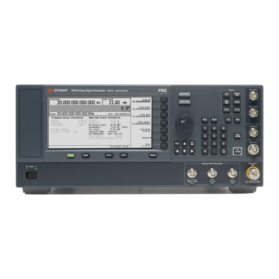
E8257D/67D PSG Signal Generators
This guide applies to the following signal generator models:
E8257D PSG Analog Signal Generator
E8267D PSG Vector Signal Generator
Due to our continuing efforts to improve our products through firmware and hardware revisions, signal
generator design and operation may vary from descriptions in this guide. We recommend that you use the
latest revision of this guide to ensure you have up-to-date product information. Compare the print date of this
guide (see bottom of page) with the latest revision, which can be downloaded from the following website:
http://www.agilent.com/find/psg
Manufacturing Part Number: E8251-90352
Printed in USA
January 2005
© Copyright 2004, 2005 Agilent Technologies, Inc.
Advertisement
Table of Contents

Related Manuals for Agilent Technologies E8257D/67D


Summary of Contents for Agilent Technologies E8257D/67D
- Page 1 Compare the print date of this guide (see bottom of page) with the latest revision, which can be downloaded from the following website: http://www.agilent.com/find/psg Manufacturing Part Number: E8251-90352 Printed in USA January 2005 © Copyright 2004, 2005 Agilent Technologies, Inc.
- Page 2 Notice The material in this document is provided “as is,” and is subject to change without notice in future editions. Further, to the maximum extent permitted by applicable law, Agilent disclaims all warranties, either express or implied with regard to this manual and to any of the Agilent products to which it pertains, including but not limited to the implied warranties of merchantability and fitness for a particular purpose.
-
Page 3: Table Of Contents
Returning a Signal Generator to Agilent Technologies ........ - Page 4 Contents 4. Regulatory Information ............33 Statement of Compliance .
-
Page 5: Safety Information
Safety Information Instrument Markings The following markings are used on the signal generator. Familiarize yourself with each marking and its meaning before operating the signal generator. The instruction manual symbol. The product is marked with this symbol when it is necessary for the user to refer to the instructions in the manual. -
Page 6: Warnings, Cautions, And Notes
Safety Information Warnings, Cautions, and Notes Warnings, Cautions, and Notes The following safety notations are used throughout this manual. Familiarize yourself with each notation and its meaning before operating the signal generator. WARNING Warning denotes a hazard. It calls attention to a condition or situation that could result in personal injury or loss of life. -
Page 7: Getting Started
Getting Started... -
Page 8: Checking The Shipment
• documentation CD-ROM CD-ROM contents are also available in hard copy format. Refer to “E8257D/67D PSG Documentation” on page 13 • three-prong ac power cord specific to geographic location 3. Verify that any options ordered are included with the shipment by checking the packing literature included with the shipment. -
Page 9: Meeting Electrical And Environmental Requirements
Meeting Electrical and Environmental Requirements Environment The signal generator is designed for use in the following environmental conditions: • indoor use • < 15,000 feet (4,572 meters) altitude • 0 to 55 C temperature, unless otherwise specified • 80% relative humidity (maximum) for temperatures up to 31 C, decreasing linearly to 50% relative humidity at 40 C CAUTION This product is designed for use in INSTALLATION CATEGORY II and POLLUTION... -
Page 10: Line Settings
Getting Started Meeting Electrical and Environmental Requirements Line Settings The signal generator has an autoranging line voltage input. The available ac power source must meet the following conditions: Voltage: 100/115 volts nominal (90-132 volts) 230/240 volts nominal (198-254 volts) Frequency: for 100/115 volts: 50/60/400 Hz nominal for 230/240 volts: 50/60 Hz nominal Power:... -
Page 11: Ac Power Cord Localization
Getting Started Meeting Electrical and Environmental Requirements AC Power Cord Localization The ac power cord included with the signal generator is appropriate to its geographic location. However, you can order additional ac power cords for use in different areas. The following table lists the available ac power cords, illustrates plug configurations, and identifies the geographic area in which each cord is appropriate. -
Page 12: Configuring The Display
Getting Started Configuring the Display Configuring the Display You can adjust the LCD display using features such as contrast, brightness, screen saver mode, and the screen saver delay. You can also toggle features such as inverse video, display updating in remote mode, and the screen saver on or off. -
Page 13: Updating The Display During Remote Operation
input to the front panel. The display light turns on again when any front panel key is pressed or when a remote command is sent. The screen saver is set to off at the factory. Utility Display Screen Saver Mode Press >... -
Page 14: Configuring For Remote Control
Getting Started Configuring for Remote Control Configuring for Remote Control GPIB Interface Configuration Utility GPIB/RS-232 LAN 1. Press > 2. Use the numeric keypad to set the desired address and press The arrow keys or the front panel knob can be used to set the desired address. The signal generator’s GPIB address is set to 19 at the factory. - Page 15 IP Address 6. Press and enter a desired address. Use the left and right arrow keys to move the cursor. Use the up and down arrow keys, front panel knob, or numeric keypad to enter an IP address. To erase the current IP address, press the NOTE To remotely access the signal generator from a different LAN subnet, you must also enter the subnet mask and default gateway.
-
Page 16: Rs-232 Interface Configuration
Getting Started Configuring for Remote Control RS-232 Interface Configuration Utility > GPIB/RS-232 LAN > RS-232 Setup 1. Press RS-232 Baud Rate 2. Press 3. Press the desired baud rate softkey. RS-232 Echo Off On 4. Press This toggles the state of the SCPI echoing on the RS-232 connection. Set as desired. Reset RS-232 5. -
Page 17: Ordering Accessories
(Option ABA) Installation Guide, the Service Guide, and the documentation CD-ROM Documentation • PDF files of the E8257D/67D PSG documentation set, including CD-ROM the Installation Guide and the Service Guide (Option CD1) • programming examples •... - Page 18 Getting Started Ordering Accessories Table 2-3 Available E8257D/67D PSG Documentation Document Type E8257D Data Sheet • available options • warranted specifications and typical performance E8267D Data Sheet • available options • warranted specifications and typical performance User’s Guide • description of features and functions •...
-
Page 19: Proper Usage And Cleaning
Use a dry cloth, or one slightly dampened with water, to clean the external case parts. WARNING To prevent electrical shock, disconnect the Agilent PSG E8257D/67D Signal Generator from mains before cleaning. Use a dry cloth or one slightly dampened with water to clean the external case parts. -
Page 20: Contacting Agilent Sales And Service Offices
Assistance with test and measurements needs and information on finding a local Agilent office are available on the Internet at: http://www.agilent.com/find/assist You can also purchase E8257D/67D PSG accessories or documentation items on the Internet at: http://www.agilent.com/find/psg If you do not have access to the Internet, please contact your field engineer. -
Page 21: Returning A Signal Generator To Agilent Technologies
Returning a Signal Generator to Agilent Technologies To return your signal generator to Agilent Technologies for servicing, follow these steps: 1. Gather as much information as possible regarding the signal generator’s problem. 2. Call the phone number listed on the Internet (http://www.agilent.com/find/assist) that is specific to your geographic location. - Page 22 Getting Started Returning a Signal Generator to Agilent Technologies Chapter 2...
-
Page 23: Operation Verification
Operation Verification Operation verification is a series of tests that, when completed, will either ensure that the signal generator is operating correctly, or will assist in pointing to the problem area. Operation verification does not ensure performance to specifications, but should provide a level of confidence that the signal generator is operating correctly within a minimum amount of time. -
Page 24: Performing A Self-Test
Operation Verification Performing a Self-Test Performing a Self-Test The self-test is a series of internal tests that checks different signal generator functions. If this test fails, refer “Self-Test Failure” on page 21 Perform the following procedure to run a self-test: 1. -
Page 25: Self-Test Failure
2. If the self-test continues to fail, send the signal generator to an Agilent service center for repair, with a detailed description of the failed test(s) and any other error messages that appeared on the display. “Returning a Signal Generator to Agilent Technologies” on page 17 Chapter 3... -
Page 26: Checking The Maximum Leveled Power
Operation Verification Checking the Maximum Leveled Power Checking the Maximum Leveled Power Perform the following procedure to check the maximum leveled power: Preset 1. Press 2. Attach a 50 load to the RF OUTPUT. A power sensor, attenuator, or 50 termination is an example of a 50 load. - Page 27 3. Ensure that the RF OUTPUT connector is connected to a 50 load. 4. Ensure that the power level entered corresponds to the value listed in 5. Refer to Table 3-2 for the recommended equipment and measure the output power. If the measured power level is more than the power level listed in counterclockwise until the measured power level equals the power level in 6.
- Page 28 Operation Verification Checking the Maximum Leveled Power Table 3-1 Frequency and Power Level Limits Instrument Option Standard E8257D 11 dBm Option 520 11 dBm With Option 1E1 E8257D 7 dBm Option 540 7 dBm With Option 1E1 7 dBm E8257D 3 dBm Option 550 and 3 dBm...
-
Page 29: Checking The Output Power
Checking the Output Power This test verifies the CW output power from the signal generator. If this test fails, refer to Output Power” on page 32 for further instructions. Table 3-2 shows the recommended equipment for use with the E8257D signal generator when performing this test. - Page 30 Operation Verification Checking the Output Power Table 3-2 Recommended Equipment for the E8257D E8257D E8257D E8257D Option Option Option Table 3-3 Recommended Equipment for the E8267D E8267D E8267D E8667D Option Option Option E8257D Option Test Equipment Adapter, 3.5 (f) to (f) Adapter, 3.5 (f) to Type-N (m)
- Page 31 Table 3-3 Recommended Equipment for the E8267D E8267D E8267D E8667D Option Option Option Chapter 3 Test Equipment Adapter, Agilent 1250-1749 APC 3.5 (f) to APC 3.5 (f) to (f) adapter Adapter, Agilent 1250-1744 APC 3.5 (f) to APC 3.5 (f) to Type-N (m) adapter Type-N (m) Operation Verification Checking the Output Power...
- Page 32 Operation Verification Checking the Output Power Perform the following procedure to check the signal generator output power: 1. Zero and calibrate the power sensor to the power meter as shown: 2. Connect the equipment as shown: Preset 3. Press RF On/Off 4.
- Page 33 Table 3-4 Leveled Output Power Limits, E8257D Option 520 Frequency Amplitude Option 250 kHz None 1E1 & 1EA 3.2 GHz None 1E1 & 1EA 20 GHz None 1E1 & 1EA Chapter 3 E8257D Limits Frequency ±0.6 250 kHz ±0.6 ±0.6 ±0.6 ±0.8 3.2 GHz...
- Page 34 Operation Verification Checking the Output Power Table 3-5 Leveled Output Power Limits, E8257D cont. Option 550 Frequency Amplitude Option 250 kHz None 1E1 & 1EA 3.2 GHz None 1E1 & 1EA 20 GHz None 1E1 & 1EA 40 GHz None 1E1 &...
- Page 35 Table 3-5 Leveled Output Power Limits, E8257D cont. Option 550 Frequency Amplitude Option 60 GHz None 1E1 & 1EA 67 GHz None 1E1 & 1EA Table 3-6 Leveled Output Power Limits, E8267D Option 520 Frequency Amplitude Option 250 kHz None 3.2 GHz None 20 GHz...
-
Page 36: Problems With Output Power
Operation Verification Checking the Output Power Problems with Output Power If a problem occurs when verifying output power levels, perform the following procedure: 1. Verify the power sensor being used in this test is the appropriate sensor. 2. Verify the power sensor calibration factors, if required, are correct. 3. -
Page 37: Regulatory Information
Regulatory Information... -
Page 38: Statement Of Compliance
Sales and Service Offices” on page Certification Agilent Technologies certifies that this product met its published specifications at the time of shipment from the factory. Agilent Technologies further certifies that its calibration measurements are traceable to the United States National Institute of Standards and Technology, to the extent allowed by the Institute’s calibration facility, and to the calibration facilities of other International Standards Organization members. -
Page 39: Compliance With Canadian Emc Requirements
Regulatory Information Compliance with Canadian EMC Requirements Compliance with Canadian EMC Requirements This is to declare that this ISM device complies with Canadian ICES-001. (Cet appareil ISM est conforme a la norme NMB du Canada.) Chapter 4... - Page 40 Regulatory Information Compliance with Canadian EMC Requirements Chapter 4...
- Page 41 AC power cord, 6, AC symbol, accessories, address, GPIB altitude requirements, assistance, Australian Communications Authority (C-tick) mark, brightness adjustment, Canadian EMC requirements, Canadian Standards Association (CSA) mark, CE mark, cleaning, configure display, contrast adjustment, CSA mark, C-tick mark, DHCP configuration, display adjustments, 8, documentation, electrical requirements,...
- Page 42 Index troubleshooting maximum leveled power, output power, self-test, ventilation requirements, verification, operation, Index...