Siemens et 200sp User Manual
Server module
Hide thumbs
Also See for et 200sp:
- System manual (320 pages) ,
- Manual (270 pages) ,
- Operating instructions manual (166 pages)
Table of Contents
Advertisement
Quick Links
Advertisement
Table of Contents

Related Manuals for Siemens et 200sp


Summary of Contents for Siemens et 200sp
- Page 2 ___________________ Server module Preface (6ES7193-6PA00-0AA0) ___________________ Documentation guide ___________________ SIMATIC Product overview ___________________ Parameters/address space ET 200SP Server module ___________________ Diagnostics alarms (6ES7193-6PA00-0AA0) ___________________ Technical specifications Manual ___________________ Parameter data record ___________________ Dimensional drawing 03/2015 A5E03575337-AB...
- Page 3 Note the following: WARNING Siemens products may only be used for the applications described in the catalog and in the relevant technical documentation. If products and components from other manufacturers are used, these must be recommended or approved by Siemens. Proper transport, storage, installation, assembly, commissioning, operation and maintenance are required to ensure that the products operate safely and without any problems.
-
Page 4: Preface
Siemens recommends strongly that you regularly check for product updates. For the secure operation of Siemens products and solutions, it is necessary to take suitable preventive action (e.g. cell protection concept) and integrate each component into a holistic, state-of-the-art industrial security concept. -
Page 5: Table Of Contents
Table of contents Preface ..............................4 Documentation guide ..........................6 Product overview ............................ 8 Properties ..........................8 Parameters/address space ........................9 Parameters ..........................9 Explanation of the parameters ....................10 Address space ........................10 3.3.1 Input data for interface modules with maximum 12 I/O modules ........... 12 3.3.2 Input data for interface modules with maximum 32 I/O modules ........... -
Page 6: Documentation Guide
Documentation guide The documentation for the SIMATIC ET 200SP distributed I/O system is arranged into three areas. This arrangement enables you to access the specific content you require. Basic information The system manual describes in detail the configuration, installation, wiring and commissioning of the SIMATIC ET 200SP. - Page 7 Documentation guide Manual Collection ET 200SP The Manual Collection contains the complete documentation on the SIMATIC ET 200SP distributed I/O system gathered together in one file. You can find the Manual Collection on the Internet (http://support.automation.siemens.com/WW/view/en/84133942). My Documentation Manager The My Documentation Manager is used to combine entire manuals or only parts of these to your own manual.
-
Page 8: Product Overview
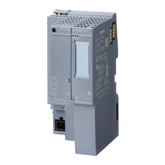
View of the server module Properties The module has the following technical properties: ● Closes off the backplane bus of the ET 200SP ● Contains a support for 3 spare fuses (5 × 20 mm) The module supports the following functions: ●... -
Page 9: Parameters/Address Space
Parameters for the server module The effective range of the configurable parameter depends on the type of configuration. Possible configuration: Distributed operation on PROFINET IO in an ET 200SP system. When assigning parameters in the user program, use the "WRREC" instruction to transfer the parameter to the module by means of data records, see section Parameter assignment and structure of parameter data record (Page 19). -
Page 10: Explanation Of The Parameters
Explanation of the parameters Group diagnostics: No supply voltage L+ When you enable this parameter, the ET 200SP generates one diagnostic per potential group (as group information) when the supply voltage L+ fails. This function does not depend on enabling the parameter "Diagnostics: No supply voltage L+"... - Page 11 Parameters/address space 3.3 Address space Length of input data The length of the input data depends on the CPU/interface module: ● Interface module with 12 I/O modules maximum configuration: 2/4 bytes ● Interface module with 32 I/O modules maximum configuration: 4/8 bytes ●...
-
Page 12: Input Data For Interface Modules With Maximum 12 I/O Modules
Input data for interface modules with maximum 12 I/O modules Configuration with enabled status detection of the supply voltage L+ (2 bytes of input data) You can read out the following status for each I/O module of the ET 200SP in the input data (byte 0 to 1): ●... -
Page 13: Input Data For Interface Modules With Maximum 32 I/O Modules
Input data for interface modules with maximum 32 I/O modules Configuration with enabled status detection of the supply voltage L+ (4 bytes of input data) You can read out the following status for each I/O module of the ET 200SP in the input data (byte 0 to 3): ●... -
Page 14: Input Data For Cpu/Interface Modules With Maximum 64 I/O Modules
Input data for CPU/interface modules with maximum 64 I/O modules Configuration with enabled status detection of the supply voltage L+ (8 bytes of input data) You can read out the following status for each I/O module of the ET 200SP in the input data (byte 0 to 7): ●... -
Page 15: Evaluating Feedback Voltage
Parameters/address space 3.3 Address space Note • An inserted or missing server module always signals bit=0 for the slot. • If the server module is missing, the input data is invalid. • For I/O modules without feedback voltage monitoring, the bit for the feedback voltage is the same as the bit for the missing supply voltage L+. - Page 16 Parameters/address space 3.3 Address space Feedback voltage A feedback may occur, for example, due to a crossover in a cable of a digital output module and depends on the target status of the supply voltage L+: If the supply voltage L+ of the I/O module is greater than 6 V, this is entered in the input data in the respective bit.
-
Page 17: Diagnostics Alarms
Diagnostics alarms A diagnostics alarm is output for each diagnostics event. The diagnostics alarms can, for example, be read out in the diagnostics buffer of the CPU. You can evaluate the error codes with the user program. Table 4- 1 Diagnostics alarms, their meanings and corrective measures Diagnostics alarm Error code... -
Page 18: Technical Specifications
Technical specifications Technical specifications Technical specifications of the server module 6ES7193-6PA00-0AA0 Dimensions Width 7 mm Height 117 mm Depth 36 mm Weights Weight, approx. 19 g Server module (6ES7193-6PA00-0AA0) Manual, 03/2015, A5E03575337-AB... -
Page 19: Parameter Data Record
Parameter data record Parameter assignment and structure of parameter data record Parameter assignment in the user program You can change the parameters of the module in RUN. Changing parameters in RUN The WRREC instruction is used to transfer the parameters to the module using data record 128. - Page 20 Parameter data record 6.1 Parameter assignment and structure of parameter data record Header information The following diagram shows the structure of the header information. Figure 6-2 Header information Parameters The following diagram shows the structure of the parameter in byte 2. Enable the parameter by setting the corresponding bit to "1".
-
Page 21: Dimensional Drawing
Dimensional drawing Server module Dimensional drawing of the server module ① Contact plating of mounting rail Figure A-1 Dimensional drawing of the server module Server module (6ES7193-6PA00-0AA0) Manual, 03/2015, A5E03575337-AB...