Siemens Simatic ET 200SP Manual
Analog output module aq 2xu/i hf (6es7135-6hb00-0ca1)
Hide thumbs
Also See for Simatic ET 200SP:
- System manual (320 pages) ,
- Manual (270 pages) ,
- Operating instructions manual (166 pages)

Related Manuals for Siemens Simatic ET 200SP


Summary of Contents for Siemens Simatic ET 200SP
- Page 1 SIMATIC ET 200SP Analog output module AQ 2xU/I HF (6ES7135-6HB00-0CA1) Manual Edition 02/2014 Answers for industry.
- Page 2 ___________________ Analog output module Preface AQ 2xU/I HF ___________________ Guide to documentation (6ES7135-6HB00-0CA1) ___________________ Product overview SIMATIC ___________________ Wiring ET 200SP ___________________ Analog output module Parameters/address space AQ 2xU/I HF ___________________ (6ES7135-6HB00-0CA1) Interrupts/diagnostics alarms Manual ___________________ Technical specifications ___________________ Parameter data record ___________________ Representation of analog values...
- Page 3 Note the following: WARNING Siemens products may only be used for the applications described in the catalog and in the relevant technical documentation. If products and components from other manufacturers are used, these must be recommended or approved by Siemens. Proper transport, storage, installation, assembly, commissioning, operation and maintenance are required to ensure that the products operate safely and without any problems.
-
Page 4: Preface
Siemens recommends strongly that you regularly check for product updates. For the secure operation of Siemens products and solutions, it is necessary to take suitable preventive action (e.g. cell protection concept) and integrate each component into a holistic, state-of-the-art industrial security concept. -
Page 5: Table Of Contents
Table of contents Preface ..............................3 Guide to documentation .......................... 5 Product overview ............................ 7 Properties ............................7 Wiring ..............................9 Pin assignment ..........................9 Block diagram ..........................10 Parameters/address space ........................11 Output type and output ranges ....................11 Parameters .......................... -
Page 6: Guide To Documentation
Documentation for the analog output module AQ 2×U/I HF Topic Documentation Key contents System description System manual ET 200SP Application planning • distributed I/O system Installation • (http://support.automation.siemens. Wiring • com/WW/view/en/58649293) Commissioning • Designing interference- Function manual Designing Basics • free controllers... - Page 7 I/O system distributed I/O system function manuals, or product (http://support.automation.siemens. manuals. com/WW/view/en/73021864) SIMATIC manuals All current manuals for SIMATIC products are available to download free of charge on the Internet (http://www.siemens.com/simatic-tech-doku-portal). Analog output module AQ 2xU/I HF (6ES7135-6HB00-0CA1) Manual, 02/2014, A5E33062529-AA...
-
Page 8: Product Overview
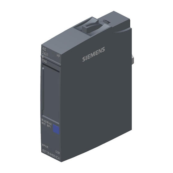
Product overview Properties Article number 6ES7135-6HB00-0CA1 View of the module Figure 2-1 View of the module AQ 2×U/I HF Analog output module AQ 2xU/I HF (6ES7135-6HB00-0CA1) Manual, 02/2014, A5E33062529-AA... - Page 9 ● Labeling strips ● Color identification labels ● Reference identification label ● Shield connection See also For more information on accessories, refer to the system manual ET 200SP distributed I/O system (http://support.automation.siemens.com/WW/view/en/58649293). Analog output module AQ 2xU/I HF (6ES7135-6HB00-0CA1) Manual, 02/2014, A5E33062529-AA...
-
Page 10: Wiring
"ET 200SP distributed I/O system" system manual. Note The first BaseUnit of a station must be a light-colored BaseUnit. Keep this in mind also during the configuration. See also ET 200SP distributed I/O system (http://support.automation.siemens.com/WW/view/en/58649293) Analog output module AQ 2xU/I HF (6ES7135-6HB00-0CA1) Manual, 02/2014, A5E33062529-AA... -
Page 11: Block Diagram
Wiring 3.2 Block diagram Block diagram Block diagram Figure 3-1 Block diagram of AQ 2xU/I HF Analog output module AQ 2xU/I HF (6ES7135-6HB00-0CA1) Manual, 02/2014, A5E33062529-AA... -
Page 12: Parameters/Address Space
You can find the tables of output ranges and overflow, overload, etc. in the section Representation of analog values (Page 30) and in the function manual Analog value processing (http://support.automation.siemens.com/WW/view/en/67989094). Analog output module AQ 2xU/I HF (6ES7135-6HB00-0CA1) Manual, 02/2014, A5E33062529-AA... -
Page 13: Parameters
Parameters/address space 4.3 Explanation of parameters Parameters Parameters of the AQ 2xU/I HF The following table lists the configurable parameters. The effective range of the configurable parameters depends on the type of configuration. The following configurations are possible: ● Distributed operation on PROFINET IO in an ET 200SP system ●... - Page 14 Parameters/address space 4.4 Address space Parameter Value range Default Reconfigu- Scope with configuration ration in software, e.g. STEP 7 (TIA Portal) GSD file GSD file PROFINET PROFIBUS Reaction to CPU STOP Turn off Channel Module Turn off • Keep last value •...
-
Page 15: Explanation Of Parameters
The substitute value is the value that the module outputs in case of a CPU STOP. Potential group Specifies that a BaseUnit with incoming voltage supply is located on this slot (see system manual ET 200SP distributed I/O system (http://support.automation.siemens.com/WW/view/en/58649293)). Analog output module AQ 2xU/I HF (6ES7135-6HB00-0CA1) Manual, 02/2014, A5E33062529-AA... -
Page 16: Address Space
Parameters/address space 4.4 Address space Address space Address space of the analog output module AQ 2×U/I HF The following figure shows the assignment of the address space for the AQ 2xU/I HF with value status (Quality Information (QI)). The addresses for the value status are only available if the value status is enabled. -
Page 17: Interrupts/Diagnostics Alarms
Interrupts/diagnostics alarms Status and error displays LED displays The figure below shows the LED displays of the AQ 2xU/I HF. ① DIAG (green/red) ② Channel status (green) ③ Channel error (red) ④ PWR (green) Figure 5-1 LED display Analog output module AQ 2xU/I HF (6ES7135-6HB00-0CA1) Manual, 02/2014, A5E33062529-AA... - Page 18 Interrupts/diagnostics alarms 5.3 Diagnostics alarms Meaning of the LED displays The following tables contain the meaning of the status and error displays. Remedies for diagnostics alarms can be found in section Diagnostics alarms (Page 19). Table 5- 1 Error display of the DIAG LED DIAG LED Meaning Backplane bus supply of the ET 200SP not OK...
-
Page 19: Interrupts
Interrupts/diagnostics alarms 5.2 Interrupts Interrupts The analog output module AQ 2×U/I HF supports diagnostic error interrupts. Diagnostic error interrupt The module generates a diagnostic error interrupt at the following events: ● Channel temporarily unavailable ● Short-circuit ● Overtemperature ● Wire break ●... -
Page 20: Diagnostics Alarms
Interrupts/diagnostics alarms 5.3 Diagnostics alarms Diagnostics alarms Diagnostics alarms A diagnostics alarm is output for each diagnostics event and the DIAG LED on the module flashes. The diagnostics alarms can, for example, be read from the diagnostics buffer of the CPU. -
Page 21: Technical Specifications
Technical specifications Technical specifications of AQ 2×U/I HF 6ES7135-6HB00-0CA1 Product type designation AQ 2xU/I HF General information Firmware version V1.0 Usable BaseUnits BU type A0, A1 Product function I&M data Yes; I&M0 to I&M3 Engineering with STEP 7 TIA Portal can be configured/integrated as of version V13 / V13 STEP 7 can be configured/integrated as of version V5.5 SP3 / V5.5 SP4... - Page 22 Technical specifications 6ES7135-6HB00-0CA1 Analog outputs Number of analog outputs Voltage output, short-circuit protection Voltage output, short circuit current, max. 45 mA Cycle time (all channels), min. 750 µs Output ranges, voltage 0 to 10 V Yes; 15 bits 1 to 5 V Yes;...
- Page 23 Technical specifications 6ES7135-6HB00-0CA1 Operational limit in entire temperature range Voltage in relation to output range, (+/-) ± 0.2% Current in relation to output range, (+/-) ± 0.2% Basic error limit (operational limit at 25 °C) Voltage in relation to output range, (+/-) ±...
- Page 24 Technical specifications Dimension drawing See manual ET 200SP BaseUnits (http://support.automation.siemens.com/WW/view/en/59753521) Analog output module AQ 2xU/I HF (6ES7135-6HB00-0CA1) Manual, 02/2014, A5E33062529-AA...
-
Page 25: Parameter Data Record
Parameter data record Dependencies when configuring with GSD file When configuring the module with a GSD file, remember that the settings of some parameters are dependent on each other. Configuring with a PROFINET GSD file The table lists the properties and their dependencies on the measurement type and measuring range for PROFINET. -
Page 26: Parameter Assignment And Structure Of Parameter Data Record
Parameter data record A.2 Parameter assignment and structure of parameter data record Configuring with a PROFIBUS GSD file The table lists the properties and their dependencies on the measurement type and measuring range for PROFIBUS. Measurement Measuring Diagnostics type range Underflow / overflow Wire break Load voltage L+... - Page 27 Parameter data record A.2 Parameter assignment and structure of parameter data record Structure of data record 128 Figure A-1 Structure of data record 128 Header information The figure below shows the structure of the header information. Figure A-2 Header information Analog output module AQ 2xU/I HF (6ES7135-6HB00-0CA1) Manual, 02/2014, A5E33062529-AA...
- Page 28 Parameter data record A.2 Parameter assignment and structure of parameter data record Parameters The figure below shows the structure of the parameters for channels 0 to 1. You can activate a parameter by setting the corresponding bit to "1". * x = 2 + (channel number x 6); channel number = 0 to 1 Figure A-3 Structure of byte x to x+5 for channel 0 and 1 Codes for output type...
- Page 29 Parameter data record A.2 Parameter assignment and structure of parameter data record Codes for output range The following table contains the codes for the output ranges of the analog output module. You must enter these codes in byte x+1 (see previous figure). Table A- 2 Codes for output range Output range for voltage...
-
Page 30: Representation Of Analog Values
Representation of analog values This appendix describes the analog values for all output ranges supported by the AQ 2xU/I HF analog module. Measured value resolution The digitized analog value is the same for all output values at the same nominal range. The analog values are represented as a fixed point number in the two's complement. -
Page 31: Representation Of Output Ranges
Representation of analog values B.3 Representation of analog values in the current output ranges Representation of output ranges In the following tables, you can find the digitized representation of the bipolar and unipolar range output ranges. The resolution is 16 bits. Table B- 2 Bipolar output ranges Dec. -
Page 32: Representation Of Analog Values In The Voltage Output Ranges
Representation of analog values B.3 Representation of analog values in the current output ranges Representation of analog values in the voltage output ranges The tables below list the decimal and hexadecimal values (codes) of the possible voltage output ranges. Table B- 4 Voltage output ranges ±10 V and ±5 V Values Voltage output range... -
Page 33: Representation Of Analog Values In The Current Output Ranges
Representation of analog values B.3 Representation of analog values in the current output ranges Table B- 6 Voltage output range 1 V to 5 V Values Voltage output range Range Dec. Hex. 1 to 5 V 118.519% 32767 7FFF 5.70 V Overflow* 32512 7F00... - Page 34 Representation of analog values B.3 Representation of analog values in the current output ranges Table B- 8 Current output range 0 to 20 mA Values Current output range Range Dec. Hex. 0 to 20 mA 118.5149% 32767 7FFF 21 mA Overflow* 29031 7167...