Table of Contents
Advertisement
Quick Links
Advertisement
Table of Contents

Related Manuals for Toro 74891


Summary of Contents for Toro 74891
- Page 1 Form No. 3400-855 Rev A TITAN ® MX4800, MX5400, or MX6000 Zero-Turn-Radius Riding Mower Model No. 74891—Serial No. 316000001 and Up Model No. 74892—Serial No. 316000001 and Up Model No. 74893—Serial No. 316000001 and Up *3400-855* A Register at www.Toro.com. Original Instructions (EN)
-
Page 2: Figure
California to cause cancer, birth defects, product properly and safely. or other reproductive harm. You may contact Toro directly at www.Toro.com for product It is a violation of California Public Resource Code and accessory information, help finding a dealer, or to register Section 4442 or 4443 to use or operate the engine on any your product. -
Page 3: Table Of Contents
Contents This manual identifies potential hazards and has safety messages identified by the safety-alert symbol (Figure which signals a hazard that may cause serious injury or death Safety ................4 if you do not follow the recommended precautions. Safe Operating Practices........... 4 Slope Indicator ............ -
Page 4: Safety
Safety Leveling the Mower Deck ........42 Inspecting the Belts ..........44 Replacing the Mower Belt ........44 Improperly using or maintaining the machine can result Removing the Mower..........45 in injury. To reduce the potential for injury, comply with Installing the Mower Deck........46 these safety instructions and always pay attention to the Replacing the Grass Deflector ........46 safety alert symbol, which means Caution, Warning, or... -
Page 5: Safe Handling Of Fuel
Operation Rollover-Protection System (ROPS) • • Lightning can cause severe injury or death. If lightning Do not remove the ROPS. is seen or thunder is heard in the area, do not operate • The ROPS is an integral and effective safety device. Keep the machine;... -
Page 6: Maintenance And Storage
Maintenance and Storage • Disengage drives, set parking brake, stop engine and remove key or disconnect spark-plug wire. Wait for all movement to stop before adjusting, cleaning or repairing. • Clean grass and debris from cutting unit, drives, mufflers, and engine to help prevent fires. Clean up oil or fuel spillage. -
Page 7: Slope Indicator
Slope Indicator G011841 Figure 3 This page may be copied for personal use. 1. The maximum slope you can safely operate the machine on is 15 degrees. Use the slope chart to determine the degree of slope of hills before operating. Do not operate this machine on a slope greater than 15 degrees. Fold along the appropriate line to match the recommended slope. -
Page 8: Safety And Instructional Decals
Safety and Instructional Decals Safety decals and instructions are easily visible to the operator and are located near any area of potential danger. Replace any decal that is damaged or lost. 115-9632 1. Power take-off (PTO), 5. Fast Blade control switch on 99-8936 some models 2. - Page 9 117-1194 1. Engine 130-0655 1. Fuel tank 3. Half 2. Full 4. Empty 130-0731 1. Warning—thrown object 2. Cutting hazard of hand or hazard; keep the deflector foot, mower blade—keep shield in place. away from moving parts. 130-0654 1. Transport—lock 3.
- Page 10 130-0765 1. Read the Operator's 3. Remove the key from Manual. the ignition and read the Operator's Manual before performing maintenance. 2. Height-of-cut selection 130-6927 1. Warning—always use the ROPS and wear the seat belt when seated in the operator's position. 130-6922 1.
- Page 11 132-0873 1. Thrown object hazard—keep bystanders away from the 3. Cutting/dismemberment of hand or foot—stay away from machine. moving parts. 2. Thrown object hazard, mower—do not operate the without 4. Entanglement hazard, belt—keep all guards in place. deflector, discharge cover, or grass collection system in place. 130-6996 1.
- Page 12 132–0871 1. Warning—read the Operator’s Manual; do not operate this 4. Ramp hazard—when loading onto a trailer, do not use dual vehicle unless you are trained; wear hearing protection. ramps; only use a singular ramp wide enough for the machine; back up the ramp (in reverse) and drive forward off the ramp.
-
Page 13: Product Overview
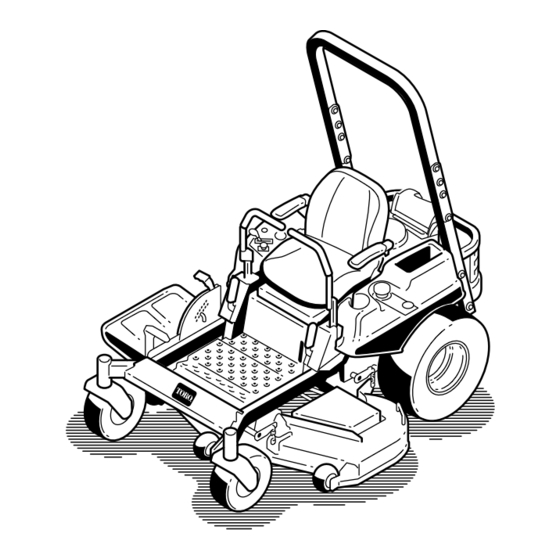
Product Overview Figure 4 1. Drive wheel 4. Motion-control levers 7. Front caster wheel 10. Deflector 2. Operator seat 5. Parking brake 8. Anti-scalp roller 3. Rollover Protection System 6. Footrest 9. Foot pedal deck lift and (ROPS) height of cut Controls Become familiar with all the controls before you start the engine and operate the machine... -
Page 14: Ignition Switch
(Figure its capabilities. Contact your Authorized Service Dealer or Distributor or go to www.Toro.com for a list of all approved attachments and accessories. g020264 Figure 6... -
Page 15: Operation
Operation WARNING Gasoline is harmful or fatal if swallowed. Long-term Note: Determine the left and right sides of the machine exposure to vapors can cause serious injury and from the normal operating position. illness. • Avoid prolonged breathing of vapors. Adding Fuel •... -
Page 16: Think Safety First
Filling the Fuel Tank Think Safety First Shut off the engine and move the motion controls to the Please read all safety instructions and symbols in the safety position. section. Knowing this information could help you or bystanders avoid injury. Important: Do not overfill fuel tank. -
Page 17: Using The Rollover Protection System (Rops)
Understanding the CAUTION Safety-Interlock System This machine produces sound levels in excess of 85 dBA at the operators ear and can cause hearing loss through extended periods of exposure. WARNING If the safety-interlock switches are disconnected or Wear hearing protection when operating this damaged, the machine could operate unexpectedly, machine. -
Page 18: Checking The Engine-Oil Level
Checking the Engine-Oil Level Operating the Throttle Before you start the engine and use the machine, check The throttle control can be moved between the S the oil level in the engine crankcase; refer to Checking the positions (Figure 12). Engine-Oil Level (page 31). -
Page 19: Operating The Ignition Switch
Operating the Ignition Switch 1. Turn the ignition key to the S position (Figure 14). TART Note: When the engines starts, release the key. Note: Additional starting cycles may be required when starting the engine for the first time after the fuel system has been without fuel completely. -
Page 20: Operating The Blade-Control Switch (Pto)
Disengaging the Blade-Control Switch (PTO) G009174 Figure 18 Driving the Machine The throttle control regulates the engine speed as measured in rpm (revolutions per minute). Place the throttle control in the F position for best performance. Always operate in the full-throttle position when mowing. CAUTION Machine can spin very rapidly. -
Page 21: Driving Forward
G008952 Figure 20 Figure 19 1. Motion-control 4. Backward Driving Backward lever—N EUTRAL position Note: Always use caution when backing up and turning. 2. Center, unlocked position 5. Front of the machine 1. Move the levers to the center, unlocked position. 3. -
Page 22: Stopping The Machine
Stopping the Machine WARNING Children or bystanders may be injured if they move or attempt to operate the machine while it is unattended. Always remove the ignition key and move the motion-control levers outward to the P position when leaving the machine unattended, even if just for a few minutes. -
Page 23: Adjusting The Anti-Scalp Rollers
4. Align the bolt and anti-scalp roller in the hole of the bracket that matched the closest height-of-cut position (Figure 24). 5. Insert the bolt into the bracket hole and secure the bolt and anti-scalp roller with the flange nut (Figure 24). -
Page 24: Adjusting The Motion-Control Levers
Adjusting the Motion-Control Note: Ensure that the left and right bypass levers are rearward and locked before moving the machine. Levers Adjusting the Height Note: Repeat the adjustment for the opposite control lever. The motion-control levers can be adjusted higher or lower for maximum operator comfort (Figure 27). -
Page 25: Using The Side Discharge
Using the Side Discharge Transporting the Machine Use a heavy-duty trailer or truck to transport the machine. The mower has a hinged grass deflector that disperses Ensure that the trailer or truck has all necessary brakes, clippings to the side and down toward the turf. lighting, and marking as required by law. - Page 26 Important: Do not use narrow individual ramps for each side of the machine. Ensure the ramp is long enough so that the angle with the ground does not exceed 15 degrees (Figure 31). On flat ground, this requires a ramp to be at least 4 times as long as the height of the trailer or truck bed to the ground.
-
Page 27: Operating Tips
If a blade is damaged or worn, replace more than that is not recommended unless grass is sparse, or it immediately with a genuine Toro replacement blade. it is late fall when grass grows more slowly. -
Page 28: Maintenance
Maintenance Recommended Maintenance Schedule(s) Maintenance Service Maintenance Procedure Interval • Change the hydraulic filter and fluid. After the first 50 hours • Check the safety-interlock system. • Check the air cleaner for dirty, loose or damaged parts. • Check the engine-oil level. Before each use or daily •... -
Page 29: Premaintenance Procedures
Premaintenance Procedures Service-Interval Chart Figure 32 Located on the seat pan underside 1. Read the Operator's Manual before performing any 4. Check the hydraulic oil every 25 hours. maintenance. 2. Check the engine oil every 8 hours. 5. Check the caster wheel tire pressure every 25 hours. 3. -
Page 30: Engine Maintenance
Engine Maintenance WARNING Contact with hot surfaces may cause personal injury. Keep hands, feet, face, clothing and other body parts away the muffler and other hot surfaces. Servicing the Air Cleaner Service Interval: Before each use or daily—Check the air cleaner for dirty, loose or damaged parts. -
Page 31: Servicing The Engine Oil
3. Remove the foam and paper elements (Figure 35). 4. Remove the foam element from the paper element (Figure 35). SAE 30 g017552 Figure 36 Figure 35 1. Air-cleaner cover 3. Paper element Checking the Engine-Oil Level 2. Foam element Service Interval: Before each use or daily—Check the engine-oil level. - Page 32 Changing the Engine Oil and the Engine-Oil Filter Service Interval: Every 100 hours—Change the engine oil and the engine-oil filter. Note: The drain plug is attached to the drain hose. Note: Dispose of the used oil at a recycling center. Fill with oil as specified in the “Viscosity Grades”...
-
Page 33: Servicing The Spark Plug
g027478 Figure 41 Checking the Spark Plug Important: Do not clean the spark plug(s). Always replace the spark plug(s) when it has: a black coating, worn electrodes, an oily film, or cracks. Note: If you see light brown or gray on the insulator, the engine is operating properly. -
Page 34: Cleaning The Blower Housing
Installing the Spark Plug Fuel System Tighten the spark plug to 27 N•m (20 ft-lb) as shown in Maintenance Figure DANGER In certain conditions, gasoline is extremely flammable and highly explosive. A fire or explosion from gasoline can burn you and others and can damage property. -
Page 35: Electrical System Maintenance
Electrical System Maintenance Servicing the Battery g0281 10 Service Interval: Monthly DANGER Battery electrolyte contains sulfuric acid which is a deadly poison and causes severe burns. Do not drink electrolyte and avoid contact with skin, eyes or clothing. Wear safety glasses to shield your eyes and rubber gloves to protect your hands. -
Page 36: Servicing The Fuses
1. Charge battery for 10 to 15 minutes at 25 to 30 amps or 30 minutes at 10 amps. 2. When the battery is fully charged, unplug the charger from the electrical outlet, then disconnect the charger leads from the battery posts (Figure 46). -
Page 37: Drive System Maintenance
Drive System Maintenance Checking the Tire Pressure Service Interval: Every 25 hours—Check tire pressure. Maintain the air pressure in the front and rear tires as specified. Uneven tire pressure can cause uneven cut. Check the pressure at the valve stem (Figure 49). -
Page 38: Hydraulic System Maintenance
Maintenance the parking brake. 2. Locate the filter and guards on each transaxle drive Oil Type: Toro HYPR-OIL® 500 or 20W-50 motor oil. system and remove the 3 screws securing the filter guard (Figure 51). -
Page 39: Bleeding The Hydraulic System
Bleeding the Hydraulic System 6. Install the second vent plug and torque it to 20 N•m (180 in-lb). 1. Raise the rear of machine up and support it with jack 7. Continue to add fluid through the expansion reservoir stands (or equivalent support) just high enough to until it reaches the Full Cold line on the expansion allow the drive wheels to turn freely. -
Page 40: Mower Deck Maintenance
File down any nicks and sharpen the blades as necessary. If a blade is damaged or worn, replace it immediately with a genuine Toro replacement blade. For Checking for Bent Blades convenient sharpening and replacement, you may want to keep extra blades on hand. -
Page 41: Removing The Blades
Note: If a bent blade is replaced with a new blade, and the dimension obtained continues to exceed 3mm (1/8 inch), the blade spindle could be bent. Contact an Authorized Toro Dealer for service. B. If the variance is within constraints, move to the next blade. -
Page 42: Leveling The Mower Deck
Installing the Blades 1. Install the blade onto the spindle shaft (Figure 59). Important: The curved part of the blade must be pointing upward toward the inside of the mower to ensure proper cutting. 2. Install the spring disk and blade bolt with the spring disk cone installed toward the bolt head (Figure 59). - Page 43 Figure 62 Figure 63 1. Blades side to side 3. Measure from the tip of the 1. Blades front to rear 3. Measure from the tip of the blade to the flat surface blade to the flat surface here. here. 2.
-
Page 44: Inspecting The Belts
6. Remove the floor pan to access the idler pulley. 2. Chain 4. Adjustment bolt 7. Using a spring removal tool, (Toro Part No. 92-5771), remove the idler spring from the deck post to remove 6. Ensure that there is tension on all 4 chains (Figure 65). -
Page 45: Removing The Mower
(Figure 67). Be careful when removing the belt. 11. Using a spring-removal tool, (Toro Part No. 92-5771), install the idler spring over the deck post and placing tension on the idler pulley and mower belt (Figure 66). -
Page 46: Installing The Mower Deck
Installing the Mower Deck 1. Park the machine on a level surface and disengage the blade-control switch. 2. Move the motion-control levers outward to the position, shut off the engine, remove EUTRAL the key, set the parking brake, and wait for all moving parts to stop before leaving the operating position. -
Page 47: Cleaning
Cleaning Washing the Underside of the Mower Service Interval: After each use—Clean the mower housing. Wash the underside of the mower after each use to prevent grass buildup for improved mulch action and clipping dispersal. 1. Park the machine on a level surface and disengage the blade-control switch. -
Page 48: Disposing Of Waste
Storage 7. Turn the water off and remove the coupling from the washout fitting. Note: If the mower is not clean after one washing, Cleaning and Storage soak it and let it stand for 30 minutes. Then repeat the 1. Disengage the blade-control switch (PTO), set the process. - Page 49 C. Shut off the engine, allow it to cool, and drain the fuel tank. D. Restart the engine and run it until it stops. E. Dispose of fuel properly. Recycle the fuel according to local codes. Important: Do not store stabilizer/conditioned fuel over 90 days.
-
Page 50: Troubleshooting
Troubleshooting Problem Possible Cause Corrective Action The starter does not crank. 1. The blade-control switch (PTO) is 1. Move the blade-control switch (PTO) engaged. to disengaged. 2. The parking brake is not on. 2. Set the parking brake. 3. The drive levers are not in 3. - Page 51 Problem Possible Cause Corrective Action The machine does not drive. 1. The by pass valves are not closed 1. Tighten the by pass valves. tight. 2. The pump belt is worn, loose or broken. 2. Change the belt. 3. The pump belt is off a pulley. 3.
-
Page 52: Schematics
Schematics Wire Diagram (Rev. A) - Page 53 Notes:...
- Page 54 Notes:...
- Page 55 Notes:...
- Page 56 Countries Other than the United States or Canada This warranty is not valid in Mexico. Customers who have purchased Toro products outside the United States or Canada should contact their Toro Distributor (Dealer) to obtain guarantee policies for your country, province, or state. If for any reason you are dissatisfied with your Distributor's service or have difficulty obtaining guarantee information, contact the Toro importer.