Table of Contents
Advertisement
Advertisement
Table of Contents

Related Manuals for Toro 74871


Summary of Contents for Toro 74871
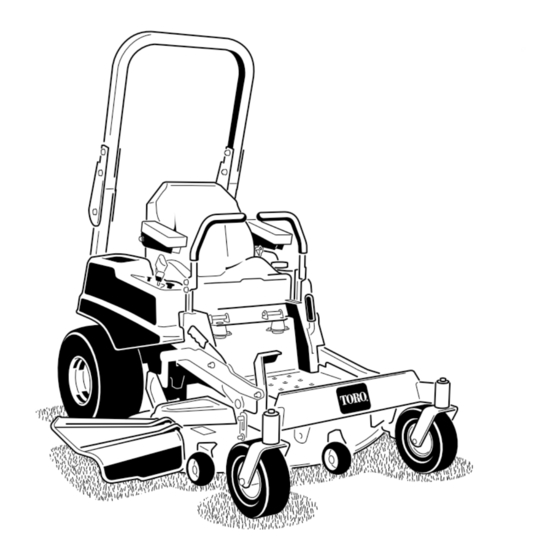
- Page 1 Form No. 3372-976 Rev A TITAN MX4880 Zero-Turn-Radius Riding Mower Model No. 74871—Serial No. 312000001 and Up G015749 To register your product or download an Operator's Manual or Parts Catalog at no charge, go to www.Toro.com. Original Instructions (EN)
-
Page 2: Figure 1
Removing standard original equipment parts and accessories may alter the warranty, traction, and G015032 safety of the machine. Failure to use original Toro parts could cause serious injury or death. Making Figure 1 unauthorized changes to the engine, fuel or venting 1. -
Page 3: Table Of Contents
Safety ................4 Changing the Hydraulic System Filter and Safe Operating Practices ........4 Oil..............41 Toro Riding Mower Safety ........6 Mower Deck Maintenance ........43 Slope Indicator............. 7 Servicing the Cutting Blades ....... 43 Safety and Instructional Decals ......8 Mower Deck Leveling......... -
Page 4: Safety
• Always wear eye protection when operating the to the instructions found in the ANSI standard below mower. can be found in Toro Riding Mower Safety at the end • Data indicates that operators, age 60 years and of this section. - Page 5 Wheels dropping over edges can cause A hitch kit is available for this machine and can be rollovers, which may result in serious injury, death obtained by contacting an Authorized Toro Dealer. or drowning. Do not tow without first installing this manufacturer •...
-
Page 6: Toro Riding Mower Safety
• Never store the machine or fuel container inside where there is an open flame, such as near a water • Use only genuine Toro replacement parts to ensure heater or furnace. that original standards are maintained. • Never fill containers inside a vehicle or on a truck or Toro Riding Mower Safety trailer with a plastic liner. -
Page 7: Slope Indicator
Slope Indicator G011841 Figure 3 This page may be copied for personal use. 1. The maximum slope you can safely operate the machine on is 15 degrees. Use the slope chart to determine the degree of slope of hills before operating. Do not operate this machine on a slope greater than 15 degrees. Fold along the appropriate line to match the recommended slope. -
Page 8: Safety And Instructional Decals
Safety and Instructional Decals Safety decals and instructions are easily visible to the operator and are located near any area of potential danger. Replace any decal that is damaged or lost. 117-1158 99-8936 1. Bypass lever position for 2. Bypass lever position for operating the machine pushing the machine 1. - Page 9 93-7009 1. Warning—don't operate the mower with the deflector up or removed; keep the deflector in place. 2. Cutting/dismemberment hazard of hand or foot, mower blade—stay away from moving parts. 117-5344 1. Lock 2. Read the Operator's Manual Manufacturer's Mark 1.
- Page 10 107-3069 1. Warning–there is no rollover protection when the roll bar is down. 2. To avoid injury or death from a rollover accident, keep the 115-9644 roll bar in the fully raised and locked position and wear the seat belt. Lower the roll bar only when absolutely 1.
- Page 11 Battery Symbols Some or all of these symbols are on your battery 1. Explosion hazard 6. Keep bystandersa safe distance from the battery. 2. No fire, open flame, or 7. Wear eye protection; smoking. explosive gases can cause blindness and other injuries 3.
- Page 12 120-5466 1. Warning—read the Operator's Manual. 5. Loss of traction/control hazard, slopes—loss of traction/control on a slope, disengage the blade control switch (PTO), proceed off the slope slowly. 2. Warning—read the instructions before servicing or performing 6. Crushing/dismemberment hazard of bystanders, maintenance;...
-
Page 13: Setup
Setup Loose Parts Use the chart below to verify that all parts have been shipped. Procedure Description Qty. – No parts required Connect the battery. – No parts required Check the mower adjustment. Ignition Key Hose coupling Operator's Manual Complete the Setup. Engine Operator's Manual Operator Training Material Connecting the Battery... - Page 14 If needed, remove the upper bolt, washer and nut and raise the motion control levers to the upright position. Secure the motion control levers. Refer to Adjusting the Motion Control Levers in the Operation Section. Raising the ROPS Raise the ROPS into the upright position and secure it in place.
-
Page 15: Product Overview
Product Overview G015763 Figure 5 1. Drive wheel 4. Motion control levers 7. Front caster wheel 10. Deflector 2. Operator seat 5. Parking brake 8. Anti-scalp roller 3. Roll over protection system 6. Footrest 9. Foot pedal deck lift and (ROPS) height-of-cut G014766... -
Page 16: Controls
Controls switch (PTO) is engaged. Use these times for scheduling regular maintenance (Figure 7). Become familiar with all the controls before you start the engine and operate the machine (Figure 7). Fuel Gauge The fuel window located below the operator position can be used to verify the level of gasoline in the tank (Figure 8). -
Page 17: Operation
Contact your could help you, your family, pets or bystanders avoid Authorized Service Dealer or Distributor or go to injury. www.Toro.com for a list of all approved attachments and accessories. DANGER Mowing on wet grass or steep slopes can cause sliding and loss of control. -
Page 18: Using The Rollover Protection System (Rops)
G015033 Figure 9 1. Safe Zone-use the machine here G015034 2. Use walk behind mower and/or hand trimmer near drop-offs Figure 10 and water. 3. Water Important: Always use the seat belt with the roll bar in the fully raised position. Using the Rollover Protection 3. -
Page 19: Adding Fuel
Adding Fuel DANGER • For best results, use only clean, fresh, unleaded In certain conditions during fueling, static gasoline with an octane rating of 87 or higher electricity can be released causing a spark which ((R+M)/2 rating method). can ignite the gasoline vapors. A fire or explosion from gasoline can burn you and others and can •... -
Page 20: Checking The Engine Oil Level
Note: A fuel stabilizer/conditioner is most effective when mixed with fresh gasoline. To minimize the chance of varnish deposits in the fuel system, use fuel stabilizer at all times. Fuel Gauge Use the fuel window below the operator to verify the level of gasoline before filling the tank (Figure 12). -
Page 21: Operating The Throttle
Releasing the Parking Brake G010079 Figure 15 Operating the Throttle The throttle control can be moved between Fast and Slow positions (Figure 16). G008959 Figure 17 Always use the fast position when turning on the mower deck with the blade control switch (PTO). 1. -
Page 22: Starting And Stopping The Engine
Starting and Stopping the on the Choke control and let the engine run for a few seconds. Then push down the Choke control. Engine Repeat as required. Note: Additional starting cycles may be required Starting the Engine when starting the engine for the first time after the 1. -
Page 23: Operating The Mower Blade Control Switch (Pto)
Disengaging the Blade Control Switch (PTO) 00:60 Sec G009174 Figure 23 The Safety Interlock System WARNING If safety interlock switches are disconnected or damaged the machine could operate unexpectedly causing personal injury. • Do not tamper with the interlock switches. •... -
Page 24: Driving Forward Or Backward
Using the Motion Control Levers Try starting the engine; the engine should not crank. Repeat with the other motion control lever. 3. While sitting on the seat, engage the parking brake, move the blade control switch to Off, and lock the motion control levers in neutral. -
Page 25: Stopping The Machine
blade control switch (PTO), and turn the ignition key to off. Set the parking brake when you leave the machine; refer to Setting the Parking Brake. Remember to remove the key from the ignition switch (Figure 21). CAUTION Children or bystanders may be injured if they move or attempt to operate the tractor while it is unattended. -
Page 26: Adjusting The Anti-Scalp Rollers
Adjusting the Height-of-Cut 2. Remove the pin from the height-of-cut bracket (Figure 28). The height-of-cut can be adjusted from 1-1/2 to 3. Select the lower hole on the lock decal and insert 4-1/2 inch (38 to 114 mm) in 1/4 inch (6 mm) the pin (Figure 28). -
Page 27: Positioning The Seat
Positioning the Seat Adjusting the Tilt The motion control levers can be tilted fore or aft for The seat can move forward and backward. Position the maximum operator comfort. seat where you have the best control of the machine and are most comfortable. 1. -
Page 28: Using The Side Discharge
Operating Tips Fast Throttle Setting For best mowing and maximum air circulation, operate the engine at the fast throttle position. Air is required to thoroughly cut grass clippings, so do not set the height-of-cut so low as to totally surround the mower by uncut grass. -
Page 29: Blade Maintenance
Check the cutter blades daily for sharpness, and for any wear or damage. File down any nicks and sharpen the blades as necessary. If a blade is damaged or worn, replace it immediately with a genuine TORO replacement blade. -
Page 30: Maintenance
Maintenance Recommended Maintenance Schedule(s) Maintenance Service Maintenance Procedure Interval • Change the engine oil. After the first 8 hours • Change the hydraulic system filter and oil. After the first 50 hours • Check the safety interlock system. • Check the engine oil level. •... - Page 31 Figure 33 Located on the seat pan underside 1. Read the Operator's Manual before performing any 4. Check the hydraulic oil every 25 hours maintenance. 2. Check the engine oil every 8 hours 5. Check the caster wheel tire pressure every 25 hours 3.
-
Page 32: Premaintenance Procedures
Premaintenance Lubrication Procedures Greasing the Bearings Raising the Seat Service Interval: Every 25 hours—Grease all lubrication points. Make sure the motion control levers are the neutral lock Grease Type: No. 2 General Purpose Lithium Base position and parking brake is set. Lift and hold the lever Grease behind the seat forward to disengage the seat latch and then lift the seat forward. -
Page 33: Engine Maintenance
Engine Maintenance Cleaning the Element Service Interval: Every 100 hours—Service the paper element. (more often in dusty, dirty WARNING conditions) Contact with hot surfaces may cause personal Every 200 hours/Yearly (whichever injury. comes first)—Replace the paper Keep hands, feet, face, clothing and other body element. -
Page 34: Changing The Engine Oil
Changing the Engine Oil WARNING Service Interval: After the first 8 hours—Change the Contact with hot surfaces may cause personal engine oil. injury. Every 100 hours—Change the engine Keep hands, feet, face, clothing and other body oil. (more often in dusty, dirty parts away the muffler and other hot surfaces. -
Page 35: Servicing The Spark Plug
4. Slowly pour approximately 80% of the specified oil into the filler tube and slowly add the additional oil to bring it to the Full mark (Figure 39). G008796 Figure 39 G008748 Figure 40 Changing the Engine Oil Filter Note: Ensure the oil filter gasket touches the engine and then an extra 3/4 turn is completed. -
Page 36: Cleaning The Cooling System
Removing the Spark Plug Installing the Spark Plug 1. Disengage the PTO, move the motion control levers Tighten the spark plug(s) to 16 ft-lb (22 N-m). to the neutral locked position and set the parking brake. 2. Stop the engine, remove the key, and wait for all moving parts to stop before leaving the operating position. -
Page 37: Fuel System Maintenance
Fuel System 5. Squeeze the ends of the hose clamps together and slide them away from the filter (Figure 45). Maintenance DANGER In certain conditions, gasoline is extremely flammable and highly explosive. A fire or explosion from gasoline can burn you and others and can damage property. -
Page 38: Electrical System Maintenance
Electrical System WARNING Maintenance Incorrect battery cable routing could damage the machine and cables causing sparks. Sparks can cause the battery gasses to explode, resulting in Servicing the Battery personal injury. • Always Disconnect the negative (black) battery Service Interval: Monthly cable before disconnecting the positive (red) cable. -
Page 39: Servicing The Fuses
Installing the Battery 1. Position battery in the tray with the terminal posts opposite from the fuel tank (Figure 46). 2. First, install the positive (red) battery cable to positive (+) battery terminal. 3. Then install the negative battery cable to the negative (-) battery terminal. -
Page 40: Drive System Maintenance
Drive System Maintenance Checking the Tire Pressure Service Interval: Every 25 hours—Check tire pressure. Maintain the air pressure in the front and rear tires as specified. Uneven tire pressure can cause uneven cut. Check the pressure at the valve stem (Figure 49). Check the tires when they are cold to get the most accurate pressure reading. -
Page 41: Hydraulic System Maintenance
Hydraulic System 2. Locate the filter and guards on each transaxle drive system (Figure 51). Remove three screws securing Maintenance the filter guard and guard. Oil Type: 20w-50 engine oil. G010254 Important: Use oil specified or equivalent. Other fluids could cause system damage. Checking the Hydraulic Oil Level Service Interval: Every 25 hours... -
Page 42: Bleeding The Hydraulic System
hydraulic filters and oil can result in irreparable damage to the transaxle drive system. Bleeding the Hydraulic System 1. Raise the rear of machine up and support with jack stands (or equivalent support) just high enough to allow drive wheels to turn freely. G010333 Figure 53 1. -
Page 43: Mower Deck Maintenance
If a blade is damaged or worn, Checking for Bent Blades replace it immediately with a genuine Toro replacement Note: The machine must be on a level surface for the blade. For convenient sharpening and replacement, you following procedure. -
Page 44: Removing The Blades
3. Opposing side of blade being moved into measurement 1/8 inch (3mm), the blade spindle could be bent. position Contact an Authorized Toro Dealer for service. B. If the variance is within constraints, move to the 5. Measure from the tip of the blade to the flat surface next blade.. -
Page 45: Mower Deck Leveling
Figure 61 1. Blade 2. Balancer Installing the Blades 1. Install the blade onto the spindle shaft (Figure 59). Important: The curved part of the blade must be pointing upward toward the inside of the mower to ensure proper cutting. 2. -
Page 46: Leveling The Mower Deck
are not within 3/16 inch (5 mm), an adjustment is required; continue to the Leveling procedure. Figure 63 1. Blades front to rear 3. Measure from the tip of the blade to the flat surface Figure 62 here 1. Blades side to side 3. -
Page 47: Inspecting The Belts
5. Recheck that blocks fit just snugly under the deck skirt. Make sure all attachment bolts are tight 5. Using a spring removal tool, (Toro part no. 92-5771), remove the idler spring from the deck post to remove 6. Verify the deck is level by checking the side-to-side tension on the idler pulley (Figure 67). -
Page 48: Removing The Mower
The spring is under tension when installed and can cause personal injury. Be careful when removing the belt. 9. Using a spring removal tool, (Toro part no. 92-5771), install the idler spring over the deck post and placing tension on the idler pulley and mower belt (Figure 67). -
Page 49: Installing The Mower
Installing the Mower 1. Park the machine on a level surface and disengage the blade control switch. 2. Move the motion control levers outward to the neutral lock position, stop the engine, remove the key, set the parking brake and wait for all moving parts to stop before leaving the operating position. -
Page 50: Cleaning
Cleaning Washing the Underside of the Mower Service Interval: Before each use or daily—Clean the mower housing. Wash the underside of the mower after each use to prevent grass buildup for improved mulch action and clipping dispersal. 1. Park the machine on a level surface and disengage the blade control switch. -
Page 51: Waste Disposal
Storage 6. Disengage the blade control switch, stop the engine, and remove the ignition key. Wait for all moving parts to stop. Cleaning and Storage 7. Turn the water off and remove the coupling from 1. Disengage the blade control switch (PTO), set the the washout fitting. - Page 52 B. Run the engine to distribute conditioned fuel through the fuel system (5 minutes). C. Stop the engine, allow it to cool, and drain the fuel tank. D. Restart the engine and run it until it stops. E. Dispose of fuel properly. Recycle as per local codes.
-
Page 53: Troubleshooting
Troubleshooting Problem Possible Cause Corrective Action Starter does not crank 1. Blade control switch (PTO) is engaged. 1. Move blade control switch (PTO) to disengaged. 2. Parking brake is not on. 2. Set the parking brake. 3. Drive levers are not in neutral lock 3. - Page 54 Problem Possible Cause Corrective Action Machine does not drive. 1. By pass valves is not closed tight. 1. Tighten the by pass valves. 2. Pump belt is worn, loose or broken. 2. Change the belt. 3. Pump belt is off a pulley. 3.
-
Page 55: Schematics
Schematics G014723 Wire Diagram (Rev. B) - Page 56 Countries Other than the United States or Canada Customers who have purchased Toro products outside the United States or Canada should contact their Toro Distributor (Dealer) to obtain guarantee policies for your country, province, or state. If for any reason you are dissatisfied with your Distributor's service or have difficulty obtaining guarantee information, contact the Toro importer.