Table of Contents
Advertisement
Visit our website at
www.MillerWelds.com
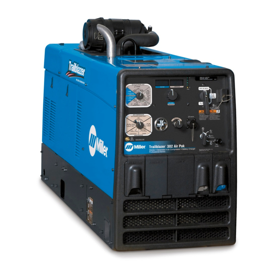
Trailblazer 302 Air Pak
OM-229 930A
2009−01
Processes
MIG (GMAW) Welding
Flux Cored (FCAW)
Stick (SMAW) Welding
TIG (GTAW) Welding
Air Plasma Cutting and Gouging
with Spectrum
Air Carbon Arc (CAC-A) Cutting
and Gouging
Description
Engine Driven Welding Generator And
Air Compressor
R
File: Engine Drive
R
Unit
™
Advertisement
Table of Contents
Troubleshooting

Related Manuals for Miller TRAILBLAZER 302 AIR PAK


Summary of Contents for Miller TRAILBLAZER 302 AIR PAK
- Page 1 Stick (SMAW) Welding TIG (GTAW) Welding Air Plasma Cutting and Gouging with Spectrum Unit Air Carbon Arc (CAC-A) Cutting and Gouging Description Engine Driven Welding Generator And Air Compressor Trailblazer 302 Air Pak ™ File: Engine Drive Visit our website at www.MillerWelds.com...
- Page 2 We know you don’t have time to do it any other way. That’s why when Niels Miller first started building arc welders in 1929, he made sure his products offered long-lasting value and superior quality.
-
Page 3: Table Of Contents
TABLE OF CONTENTS SECTION 1 − SAFETY PRECAUTIONS − READ BEFORE USING ....... . 1-1. - Page 4 TABLE OF CONTENTS SECTION 7 − COMPRESSOR OPERATION ........... . 7-1.
-
Page 5: Section 1 − Safety Precautions − Read Before Using
SECTION 1 − SAFETY PRECAUTIONS − READ BEFORE USING rom_2008−08 Protect yourself and others from injury — read and follow these precautions. 1-1. Symbol Usage DANGER! − Indicates a hazardous situation which, if Indicates special instructions. not avoided, will result in death or serious injury. The possible hazards are shown in the adjoining symbols or explained in the text. - Page 6 D Do not weld on closed containers such as tanks, drums, or pipes, FUMES AND GASES can be hazardous. unless they are properly prepared according to AWS F4.1 (see Safety Standards). Welding produces fumes and gases. Breathing these D Do not weld where the atmosphere may contain flammable dust, fumes and gases can be hazardous to your health.
-
Page 7: Engine Hazards
1-3. Engine Hazards HOT PARTS can cause severe burns. BATTERY EXPLOSION can BLIND. D Do not touch hot parts bare handed. D Always wear a face shield, rubber gloves, and protective clothing when working on a battery. D Allow cooling period before working on equip- ment. -
Page 8: Compressed Air Hazards
D Keep hands, hair, loose clothing, and tools away from moving HYDRAULIC FLUID can injure or kill. parts. D Before working on hydraulic system, turn off and lockout/tagout D Before working on hydraulic system, turn off and unit, release pressure, and be sure hydraulic pressure cannot be lockout/tagout unit, release pressure, and be sure accidentally applied. -
Page 9: Additional Symbols For Installation, Operation, And Maintenance
MOVING PARTS can injure. HOT PARTS can cause severe burns. D Do not touch hot compressor or air system D Keep away from fans, belts and rotors. parts. D Keep all doors, panels, covers, and guards D Let system cool down before touching or ser- closed and securely in place. -
Page 10: California Proposition 65 Warnings
H.F. RADIATION can cause interference. ARC WELDING can cause interference. D High-frequency (H.F.) can interfere with radio D Electromagnetic energy can interfere with navigation, safety services, computers, and sensitive electronic equipment such as micro- communications equipment. processors, computers, and computer-driven equipment such as robots. -
Page 11: Section 2 − Consignes De Sécurité − Lire Avant Utilisation
SECTION 2 CONSIGNES DE SÉCURITÉ − LIRE AVANT − UTILISATION rom_2008−08fre Se protéger, ainsi que toute autre personne travaillant sur les lieux, contre les étincelles et le métal chaud. 2-1. Signification des symboles DANGER! − Indique une situation dangereuse qui si on Indique des instructions spécifiques. - Page 12 D Porter un casque de soudage approuvé muni de verres filtrants DES PIÈCES CHAUDES peuvent approprié pour protéger visage et yeux pendant le soudage provoquer des brûlures graves. (voir ANSI Z49.1 et Z87.1 énuméré dans les normes de sécurité). D Porter des lunettes de sécurité avec écrans latéraux même sous D Ne pas toucher à...
-
Page 13: Dangers Existant En Relation Avec Le Moteur
D Placer les bouteilles debout en les fixant dans un support station- LES CHAMPS MAGNETIQUES peuvent naire ou dans un porte-bouteilles pour les empêcher de tomber ou affecter des implants médicaux. de se renverser. D Tenir les bouteilles éloignées des circuits de soudage ou autres D Porteur de simulateur cardiaque ou autre im- circuits électriques. -
Page 14: Dangers Liés À L'hydraulique
L’utilisation d’un groupe autonome L’ACIDE DE LA BATTERIE peut pro- à l’intérieur PEUT VOUS TUER EN voquer des brûlures dans les YEUX et QUELQUES MINUTES. sur la PEAU. D Ne pas renverser la batterie. D Les fumées d’un groupe autonome contient du D Remplacer une batterie endommagée. -
Page 15: Dangers Liés À L'air Comprimé
LIRE LES INSTRUCTIONS. D Lire le manuel d’utilisation avant d’installer, d’utiliser ou d’intervenir sur l’appareil. D N’utiliser que les pièces de rechange recommandées par le constructeur. D Effectuer l’entretien en respectant les manuels d’utilisation, les normes industrielles et les codes nationaux, d’état et locaux. 2-5. -
Page 16: Dangers Supplémentaires En Relation Avec L'installation, Le Fonctionnement Et La Maintenance
MÉTAL CHAUD provenant LIRE LES INSTRUCTIONS. découpage ou du gougeage à l’arc risque de provoquer un incendie ou une explosion. D Lire le manuel d’utilisation avant d’installer, d’utiliser ou d’intervenir sur l’appareil. D Ne pas découper ou gouger à proximité D N’utiliser que les pièces de rechange de produits inflammables. -
Page 17: Proposition Californienne 65 Avertissements
LE RAYONNEMENT HAUTE FRÉ- LE SOUDAGE À L’ARC risque de QUENCE (H.F.) risque de provoquer provoquer des interférences. des interférences. D L’énergie électromagnétique risque de provo- quer des interférences pour l’équipement élec- D Le rayonnement haute fréquence (H.F.) peut tronique sensible tel que les ordinateurs et provoquer des interférences avec les équipe- l’équipement commandé... -
Page 18: Information Emf
2-9. Information EMF Considérations sur le soudage et les effets de basse fréquence et des 1. Garder les câbles ensemble, les torsader, les scotcher, ou les champs magnétiques et électriques. recouvrir d’une housse. Le courant de soudage, pendant son passage dans les câbles de sou- 2. -
Page 19: Section 3 − Definitions
SECTION 3 − DEFINITIONS 3-1. Symbol Definitions Fast Fast/Slow Stop Engine Slow (Idle) (Run, Weld/Power) (Run/Idle) Start Engine Panel/Local Temperature Fuel Check Valve Engine Oil Engine Choke Battery (Engine) Clearance Read Operator’s Engine Amperes Volts Manual MIG (GMAW), Stick (SMAW) TIG (GTAW) Lift Arc TIG Wire... -
Page 20: Section 4 − Specifications
SECTION 4 − SPECIFICATIONS 4-1. Weld, Power, And Engine Specifications Rated Maximum Welding Weld Generator Fuel Welding Open-Circuit Engine Mode Output Range Power Rating Capacity Output Voltage 280 A, 32 V, 100% CC/DC 10 − 300 A Duty Cycle Kohler CH-750 Continuous: 11 kVA/kW, Air-Cooled, 300 A, 32 V, 100%... -
Page 21: Dimensions, Weights, And Operating Angles
4-4. Dimensions, Weights, and Operating Angles Dimensions 34−1/4 in. (870 mm) Height (To Top Of Air Cleaner) Width 20 in. (508 mm) Do not exceed tilt angles or engine could Depth 59−5/8 in. (1514 mm) be damaged or unit could tip. Do not move or operate unit where it could 20 in. -
Page 22: Fuel Consumption Curves
4-5. Fuel Consumption Curves A. Welding 2.25 2.00 1.75 1.50 1.25 1.00 0.75 0.50 IDLE 0.25 0.00 DC WELD AMPERES AT 100% DUTY CYCLE Auxiliary Power 2.25 2.00 1.75 1.50 1.25 1.00 0.75 0.50 IDLE 0.25 0.00 AUXILIARY POWER IN KILOWATTS Air Compressor 1.200 1.000... -
Page 23: Generator Power Curve
4-6. Generator Power Curve The AC generator power curve shows the generator power avail- able in amperes at the receptacles. Tools and motors are designed to operate within 10% of 120/240 VAC. 13,000 WATTS AC AMPERES 235 695-A 4-7. Duty Cycle Duty cycle is the percentage of 10 100% Duty Cycle at 280 Amperes DC minutes that unit can weld at rated... -
Page 24: Stick And Mig Mode Volt-Ampere Curves
4-8. Stick And MIG Mode Volt-Ampere Curves A. CC/DC Stick Mode The volt-ampere curves show the minimum and maximum voltage and amperage output capabilities of the welding generator. Curves of other settings fall between the curves shown. MIN DIG MAX DIG DC AMPERES CC/AC STICK Mode MAX DIG... -
Page 25: Tig Mode Volt-Ampere Curves
4-9. TIG Mode Volt-Ampere Curves The volt-ampere curves show the minimum and maximum voltage and amperage output capabilities of A. CC/AC TIG Mode the welding generator. Curves of other settings fall between the curves shown. AC AMPERES B. CC/DC TIG Mode DC AMPERES 235 698-A / 235 699-A OM-229 930 Page 21... -
Page 26: Section 5 − Installation
SECTION 5 − INSTALLATION 5-1. Serial Number And Rating Label Location The serial number and rating information for this product is located on the rear panel. Use rating label to determine rated output. For future reference, write serial number in space provided on back cover of this manual. 5-2. -
Page 27: Grounding Generator To Truck Or Trailer Frame
5-3. Grounding Generator To Truck Or Trailer Frame Always ground generator frame to vehicle frame to pre- vent electric shock and static electricity hazards. Also see AWS Safety & Health Fact Sheet No. 29, Grounding of Portable And Vehicle Mounted Welding Generators. -
Page 28: Engine Prestart Checks
5-4. Engine Prestart Checks Check all fluids daily. Engine must be cold and on a level surface. Unit is shipped with 10W30 engine oil. Follow run-in procedure in en- gine manual. This unit has a low oil pressure shutdown switch. However, some conditions may cause en- Full... -
Page 29: Compressor Prestart Checks
5-5. Compressor Prestart Checks Primary Oil Fill/ Check Use only Mobil 1 Synthetic ATF oil. Optional Oil Fill/Check Keep oil level threaded area of fill pipe. 236 200 Check all fluids daily. Engine must be cold ature shutdown. High oil temperature on dipstick, add oil (see compressor main- and on a level surface. -
Page 30: Connecting The Battery
5-6. Connecting the Battery Connect negative (−) battery cable last. To connect battery, open top − service door. Tools Needed: 1/2 in. Ref. 229 219-A / Ref. S-0756-D / 804 953-B 5-7. Installing Exhaust Pipe Stop engine and let cool. Engine backfire can cause se- vere burns or other injuries. -
Page 31: Weld Output Terminals
5-8. Weld Output Terminals Stop engine. Do not connect to CC and CV terminals at the same time. Work Weld Output Terminal Stick/TIG (CC) Weld Output Terminal Wire (CV) Weld Output Terminal For MIG welding, connect work cable to Work terminal and wire feeder cable to Wire (CV) terminal. -
Page 32: Selecting Weld Cable Sizes
5-10. Selecting Weld Cable Sizes* Weld Cable Size** and Total Cable (Copper) Length in Weld Circuit Not Exceeding*** 150 ft 200 ft 250 ft 300 ft 350 ft 400 ft 100 ft (30 m) or Less (45 m) (60 m) (70 m) (90 m) (105 m) -
Page 33: Connecting To The Air Compressor
(not supplied). Protect hose from rubbing on sheet metal base. Obtain optional 50 ft (15 m) air hose with 1/2 in. NPT swivel fitting (Miller Part No. 300 571). 804 953-A / WM Design OM-229 930 Page 29... -
Page 34: Section 6 − Operating Welding Generator
SECTION 6 − OPERATING WELDING GENERATOR 6-1. Engine Controls Ref. 804 857-B / Ref. 229 219-C Engine Control Switch To view engine speed: with engine running Engine Choke Control and Process Selector switch in any Stick Use switch to start engine, select speed, Use control to change engine air-fuel mix Hot position, cycle switch from Auto Speed when starting engine. -
Page 35: Voltage/Amperage Control
6-3. Voltage/Amperage Control 1 And 2 Displays Displays show weld process infor- mation (voltage and amperage) and maintenance information (hourmet- er, oil change countdown, or RPM). Meter Weld Functions: In Wire modes, Voltmeter displays preset weld voltage when not welding. Me- ters display actual voltage and am- perage when welding and for five seconds after welding has stopped. -
Page 36: Process/Contactor Switch
6-4. Process/Contactor Switch Ref. 804 857-B / Ref. 229 219-C Process/Contactor Switch Soft Arc (E 7018) - This setting provides a Medium Arc - This setting provides me- low dig/arc force setting for smooth weld dium dig/arc force for open root vertical up Weld output terminals are energized performance. -
Page 37: Stick Scratch Start
Process/Contactor Switch Settings Switch Setting Process Output On/Off Control Electrode Hot − Wire MIG (GMAW) Electrode Hot Stick (SMAW) Electrode Hot − Stick Electrode Hot Select Preferred Dig Air Carbon Arc (CAC-A) Cutting And Gouging Electrode Hot − Stick Electrode Hot Select Any Dig Electrode Hot −... -
Page 38: Lift-Arct Tig With Auto-Cratert And Auto-Stopt
6-6. Lift-Arct TIG With Auto-Cratert And Auto-Stopt Arc Start With Lift-Arc TIG Lift-Arc is used for the DCEN GTAW process when HF Start method is not permitted. Arc Start With Lift-Arc Select Lift-Arc at Process/Contac- tor switch. Turn gas on. Touch or scratch. -
Page 39: Remote Voltage/Amperage Control
6-7. Remote Voltage/Amperage Control Remote Receptacle RC4 Connect optional remote voltage/ amperage (V/A) control to RC4 (see Section 5-11). Use receptacle to connect remote control or wire feeder. When a remote voltage/amperage control is connected to the Remote receptacle, the Auto Sense Re- mote feature automatically... -
Page 40: Section 7 − Compressor Operation
SECTION 7 − COMPRESSOR OPERATION 7-1. Air Compressor Switch Weld output and generator power are reduced when the air com- pressor is on. With the compressor on, weld or generator loads will cause the en- gine to run at 3600 RPM. Air Compressor Operation Displays Displays show air compressor status... -
Page 41: Air Compressor Gauge And Regulator
7-2. Air Compressor Gauge And Regulator Ref. 804 857-A / Ref. 229 219-A / 229 807-B Air Compressor Gauge The air pressure gauge reads the air Do not set pressure above 150 psi compressor line pressure. Air pres- Air Pressure Regulator (1034 kPa). -
Page 42: Compressor Blow Down
7-4. Compressor Blow Down Blow Down Valve To prevent foaming or sudden release of pressure, allow 10 minutes after shutdown before opening the compressor oil dip- stick/fill cap or performing other compressor maintenance. To control the release of air mixed in the compressor oil (while running), the compressor goes through a blow down cycle when the com-... -
Page 43: Section 8 − Operating Auxiliary Equipment
SECTION 8 − OPERATING AUXILIARY EQUIPMENT 8-1. Generator Power Receptacles And Supplementary Protectors Ref. 229 219 RC2 and RC3 supply 60 Hz single-phase mote Receptacle RC4 from overload. If If unit does not have GFCI recep- power at weld/power speed. Maximum out- CB2 opens, RC2 does not work. -
Page 44: Simultaneous Weld And Power
8-3. Simultaneous Weld And Power This table shows simultaneous weld and power output with air compressor off. Weld Current in Amperes Total Power in Watts 120 V Receptacle Amperes 240 V Receptacle Amperes 1000 3500 5200 6700 8000 11,000 8-4. Wiring Instructions For Optional 240 Volt, Single-Phase Plug (NEMA 14-50P) The plug can be wired for a 240 V, 2-wire load or a 120/240V, 3-wire load. -
Page 45: Section 9 − Generator/Engine Maintenance
SECTION 9 − GENERATOR/ENGINE MAINTENANCE 9-1. Maintenance Label OM-229 930 Page 41... -
Page 46: Routine Generator/Engine Maintenance
9-2. Routine Generator/Engine Maintenance Use information displayed on the Voltmeter/Ammeter displays to assist in scheduling maintenance (see Section 6-3). Engine speed is regulated by an electronic governor. Engine speed adjustments may only be performed by a Factory Authorized Service Agent. Follow the storage procedure in the engine owner’s manual if the unit will not be used for an extended period. -
Page 47: Servicing Air Cleaner
9-3. Servicing Air Cleaner Stop engine. Do not run engine without air cleaner or with dirty element. En- gine damage caused by using a damaged element is not covered by the warranty. The air cleaner primary element can be cleaned but the dirt holding capac- ity of the filter is reduced with each cleaning. -
Page 48: Changing Engine Oil, Oil Filter, And Fuel Filter
9-4. Changing Engine Oil, Oil Filter, And Fuel Filter Stop engine and let cool. Oil Drain Valve Oil Filter Change engine oil and filter accord- ing to engine manual. Close valve and valve cap before adding oil and run- ning engine. Full Fill crankcase with new oil to full mark on dipstick (see Section 5-4). -
Page 49: Overload Protection
9-5. Overload Protection Stop engine. Open left side door. When a circuit breaker, supple- mentary protector or fuse opens, it usually indicates a more serious problem exists. Contact a Factory Authorized Service Agent. Supplementary Protector CB4 Supplementary Protector CB6 CB4 protects the stator winding supplying 24 volt AC output to Re- mote receptacle RC4. -
Page 50: Servicing Optional Spark Arrestor
9-6. Servicing Optional Spark Arrestor Stop engine and let cool. Spark Arrestor Screen Clean and inspect screen. Replace spark arrestor if screen wires are broken or missing. Tools Needed: 1/4 in. 804 951 / Ref. 803 572−A Notes Work like a Pro! Pros weld and cut safely. -
Page 51: Section 10 − Air Compressor Maintenance
SECTION 10 − AIR COMPRESSOR MAINTENANCE 10-1. Maintenance Stop engine before maintaining. Recycle See compressor Maintenance engine Label for important start-up and fluids. service information. Service compressor more often if used in severe conditions. Replace compressor oil and filter after the first 50 hours of operation. n = Check Z = Change ~ = Clean... -
Page 52: Compressor Maintenance Label
10-2. Compressor Maintenance Label OM-229 930 Page 48... -
Page 53: Servicing Compressor Air Cleaner And Air/Oil Separator
10-3. Servicing Compressor Air Cleaner And Air/Oil Separator Stop engine. Wait 10 minutes for compressor blow down cycle to complete be- fore performing maintenance. NOTICE − Do not run air compressor without air cleaner or with dirty element. Compressor damage caused by using a damaged element is not covered by the warranty. -
Page 54: Changing Air Compressor Oil And Filter
10-4. Changing Air Compressor Oil And Filter Tools Needed: 7/8, 15/16 in 804 950-A / 804 951-A / 804 952-A Air Compressor Oil Dipstick/Fill Remove filter by turning filter counterclock- Stop engine and let cool. wise. Apply thin coat of oil to gasket on new To change compressor oil and filter: filter. -
Page 55: Section 11 − Troubleshooting
SECTION 11 − TROUBLESHOOTING 11-1. Front Panel Display Code Information Left Display Right Display Description How/When Code Is Displayed Code is displayed when engine is running, Engine Control switch is in Run 25 − 304 Preset Weld Current or Auto Speed position, Process/Contactor switch is in Electrode Hot − Stick or TIG position, and Compressor switch is in Off or On positions. -
Page 56: Welding Troubleshooting
11-2. Welding Troubleshooting Trouble Remedy No weld output. Check weld control settings. Check weld connections. Disconnect equipment from generator power receptacles during start-up. Increase front panel and/or remote voltage/amperage control settings (see Sections 6-3 and 6-7). Check and secure connections to Remote receptacle RC4 (see Sections 5-11). Have Factory Authorized Service Agent check brushes, slip rings, and circuit boards PC1 and PC2. -
Page 57: Generator Power Troubleshooting
Trouble Remedy Tungsten electrode oxidizing and not Shield weld zone from drafts. remaining bright after conclusion of weld. Increase postflow time. Check and tighten all gas fittings. Properly prepare tungsten. 11-3. Generator Power Troubleshooting Trouble Remedy No power output. Reset supplementary protectors CB1, CB2 and/or CB3 (see Section 8-1). Have Factory Authorized Service Agent check brushes, slip rings, and circuit boards PC1 and PC2. -
Page 58: Compressor Troubleshooting
Trouble Remedy Battery discharges between uses. Place Engine Control switch in Off position when unit is not running. Clean top of battery with baking soda and water solution; rinse with clear water. Periodically recharge battery (approximately every 3 months). Replace battery. Check voltage regulator according to engine manual. - Page 59 Trouble Remedy Air compressor stops after short period Check compressor oil level (see Section 5-5). Automatic shutdown stops compressor if compressor tem- of operation. perature is too high. Circuit breaker CB5 is open. CB5 automatically resets when the compressor cools. If CB5 continues to open, contact Factory Authorized Service Agent.
-
Page 60: Section 12 − Parts List
SECTION 12 − PARTS LIST 12-1. Recommended Spare Parts Dia. Part Mkgs. Description Quantity Recommended Spare Parts ....021718 Fuse, Mintr Gl 30 Amp 32 Volt . - Page 61 Notes Work like a Pro! Pros weld and cut safely. Read the safety rules at the beginning of this manual. OM-229 930 Page 57...
-
Page 62: Section 13 − Electrical Diagrams
SECTION 13 − ELECTRICAL DIAGRAMS Figure 13-1. Circuit Diagram For Welding Generator OM-229 930 Page 58... - Page 63 228 867-F OM-229 930 Page 59...
-
Page 64: Section 14 − Generator Power Guidelines
SECTION 14 − GENERATOR POWER GUIDELINES The views in this section are intended to be representative of all engine-driven welding generators. Your unit may differ from those shown. 14-1. Selecting Equipment Generator Power Receptacles − Neutral Bonded To Frame 3-Prong Plug From Case Grounded Equipment 2-Prong Plug From Double Insulated Equipment... - Page 65 14-3. Grounding When Supplying Building Systems Equipment Grounding Terminal Grounding Cable GND/PE Use #10 AWG or larger insulated copper wire. Ground Device Use ground device as stated in electrical codes. Ground generator to system earth ground if supplying power to a premises (home, shop, farm) wiring system.
- Page 66 14-5. Approximate Power Requirements For Industrial Motors Industrial Motors Rating Starting Watts Running Watts Split Phase 1/8 HP 1/6 HP 1225 1/4 HP 1600 1/3 HP 2100 1/2 HP 3175 Capacitor Start-Induction Run 1/3 HP 2020 1/2 HP 3075 3/4 HP 4500 1400 1 HP...
- Page 67 14-7. Approximate Power Requirements For Contractor Equipment Contractor Rating Starting Watts Running Watts Hand Drill 1/4 in 3/8 in 1/2 in Circular Saw 6-1/2 in 7-1/4 in 8-1/4 in 1400 1400 Table Saw 9 in 4500 1500 10 in 6300 1800 Band Saw 14 in...
- Page 68 14-8. Power Required To Start Motor Single-Phase Induction Motor Starting Requirements Motor Start Code KVA/HP 10.0 11.2 12.5 14.0 Motor Start Code Running Amperage Motor HP Motor Voltage AC MOTOR To find starting amperage: VOLTS AMPS Step 1: Find code and use table to CODE find kVA/HP.
- Page 69 14-10. Typical Connections To Supply Standby Power Have only qualified persons perform these connections according to all applicable codes and safety practices. Fused Properly install and ground Welding Utility Disconnect this equipment according to Electrical Generator Transfer Switch Switch its Owner’s Manual and na- Output Service (If Required)
- Page 70 14-11. Selecting Extension Cord (Use Shortest Cord Possible) Cord Lengths for 120 Volt Loads If unit does not have GFCI receptacles, use GFCI-protected extension cord. Maximum Allowable Cord Length in ft (m) for Conductor Size (AWG)* Current Load (Watts) (Amperes) 350 (106) 225 (68) 137 (42)
- Page 71 Effective January 1, 2009 (Equipment with a serial number preface of LK or newer) This limited warranty supersedes all previous Miller warranties and is exclusive with no other Warranty Questions? guarantees or warranties expressed or implied. LIMITED WARRANTY − Subject to the terms and conditions...
-
Page 72: Options And Accessories
Contact the Delivering Carrier to: File a claim for loss or damage during shipment. For assistance in filing or settling claims, contact your distributor and/or equipment manufacturer’s Transportation Department. © ORIGINAL INSTRUCTIONS − PRINTED IN USA 2009 Miller Electric Mfg. Co. 2009−01...