Miller Trailblazer 302 Diesel Owner's Manual
Hide thumbs
Also See for Trailblazer 302 Diesel:
- Technical manual (81 pages) ,
- Owner's manual (68 pages) ,
- Application manual (16 pages)
Table of Contents
Troubleshooting

Related Manuals for Miller Trailblazer 302 Diesel


Summary of Contents for Miller Trailblazer 302 Diesel
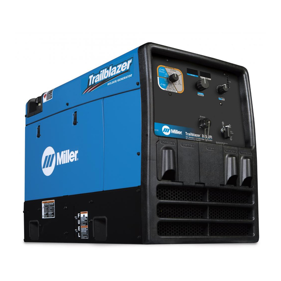
- Page 1 OM-217 454T 2011−12 Processes Stick (SMAW) Welding MIG (GMAW) Welding Flux Cored (FCAW) Welding AC/DC TIG (GTAW) Welding Description Engine Driven Welding Generator Trailblazer 302 Diesel File: Engine Drive Visit our website at www.MillerWelds.com...
- Page 2 We know you don’t have time to do it any other way. That’s why when Niels Miller first started building arc welders in 1929, he made sure his products offered long-lasting value and superior quality.
-
Page 3: Table Of Contents
TABLE OF CONTENTS SECTION 1 − SAFETY PRECAUTIONS − READ BEFORE USING ....... . 1-1. - Page 4 TABLE OF CONTENTS SECTION 10 − ELECTRICAL DIAGRAMS ........... . . SECTION 11 −...
-
Page 5: Section 1 − Safety Precautions − Read Before Using
SECTION 1 − SAFETY PRECAUTIONS − READ BEFORE USING rom_2011−10 Protect yourself and others from injury — read, follow, and save these important safety precautions and operating instructions. 1-1. Symbol Usage DANGER! − Indicates a hazardous situation which, if Indicates special instructions. not avoided, will result in death or serious injury. - Page 6 D Do not weld on containers that have held combustibles, or on FUMES AND GASES can be hazardous. closed containers such as tanks, drums, or pipes unless they are properly prepared according to AWS F4.1 and AWS A6.0 (see Welding produces fumes and gases. Breathing these Safety Standards).
-
Page 7: Engine Hazards
1-3. Engine Hazards EXHAUST SPARKS can cause fire. BATTERY EXPLOSION can injure. D Do not let engine exhaust sparks cause fire. D Always wear a face shield, rubber gloves, and protective clothing when working on a battery. D Use approved engine exhaust spark arrestor in required areas —... -
Page 8: Additional Symbols For Installation, Operation, And Maintenance
HOT METAL from air arc cutting and MOVING PARTS can injure. gouging can cause fire or explosion. D Keep away from moving parts such as fans, D Do not cut or gouge near flammables. belts and rotors. D Watch for fire; keep extinguisher nearby. D Keep all doors, panels, covers, and guards closed and securely in place. - Page 9 BATTERY CHARGING OUTPUT and BATTERY STATIC (ESD) can damage PC boards. EXPLOSION can injure. D Put on grounded wrist strap BEFORE handling Battery charging not present on all models. boards or parts. D Use proper static-proof bags and boxes to D Always wear a face shield, rubber gloves, and protective store, move, or ship PC boards.
-
Page 10: California Proposition 65 Warnings
1-6. California Proposition 65 Warnings For Gasoline Engines: Welding or cutting equipment produces fumes or gases which contain chemicals known to the State of California to Engine exhaust contains chemicals known to the State of cause birth defects and, in some cases, cancer. (California California to cause cancer, birth defects, or other reproduc- Health &... -
Page 11: Section 2 − Consignes De Sécurité − Lire Avant Utilisation
SECTION 2 CONSIGNES DE SÉCURITÉ − LIRE AVANT − UTILISATION fre_rom_2011−10 Pour écarter les risques de blessure pour vous−même et pour autrui — lire, appliquer et ranger en lieu sûr ces consignes relatives aux précautions de sécurité et au mode opératoire. 2-1. - Page 12 Il reste une TENSION DC NON NÉGLIGEABLE dans les LES RAYONS DE L’ARC peuvent sources de soudage onduleur UNE FOIS le moteur coupé. provoquer des brûlures dans les yeux et sur la peau. D Couper l’alimentation du poste et décharger les condensateurs d’entrée comme indiqué...
-
Page 13: Dangers Existant En Relation Avec Le Moteur
D Protéger les bouteilles de gaz comprimé d’une chaleur excessive, LE BRUIT peut affecter l’ouïe. des chocs mécaniques, des dommages physiques, du laitier, des flammes ouvertes, des étincelles et des arcs. Le bruit des processus et des équipements peut D Placer les bouteilles debout en les fixant dans un support station- affecter l’ouïe. -
Page 14: Dangers Liés À L'air Comprimé
LA VAPEUR ET LE LIQUIDE DE L’ACIDE DE LA BATTERIE peut pro- REFROIDISSEMENT CHAUD peuvent voquer des brûlures dans les YEUX et provoquer des brûlures. sur la PEAU. D Il est préférable de vérifier le liquide de refroi- D Ne pas renverser la batterie. dissement une fois le moteur refroidi pour éviter D Remplacer une batterie endommagée. -
Page 15: Dangers Supplémentaires En Relation Avec L'installation, Le Fonctionnement Et La Maintenance
détendre la pression et s’assurer que le circuit d’air ne peut être L’INHALATION D’AIR COMPRIMÉ risque mis sous pression par inadvertance. de provoquer des blessures ou même D Demander seulement à un personnel qualifié d’enlever la mort. les dispositifs de sécurité ou les recouvrements pour effectuer, s’il y a lieu, des travaux d’entretien et de dépannage. - Page 16 LA SORTIE DE RECHARGE et L’EXPLO- LES CHARGES ÉLECTROSTATI- SION BATTERIE peuvent QUES peuvent endommager les provoquer des blessures. circuits imprimés. D Établir la connexion avec la barrette de terre La recharge de batterie n’existe pas sur tous les avant de manipuler des cartes ou des pièces. modèles.
-
Page 17: Proposition Californienne 65 Avertissements
2-6. Proposition californienne 65 Avertissements Pour les moteurs à essence : Les équipements de soudage et de coupage produisent des fumées et des gaz qui contiennent des produits chimiques Les gaz d’échappement des moteurs contiennent des pro- dont l’État de Californie reconnaît qu’ils provoquent des mal- duits chimiques dont l’État de Californie reconnaît qu’ils formations congénitales et, dans certains cas, des cancers. -
Page 18: Section 3 − Definitions
A complete Parts List is available at www.MillerWelds.com SECTION 3 − DEFINITIONS 3-1. Symbol Definitions Fast Fast/Slow Stop Engine Slow (Idle) (Run, Weld/Power) (Run/Idle) Read Operator’s Start Engine Amperes Volts Manual Engine Oil Fuel Battery (Engine) Engine Check Valve Do not switch while Temperature Work Connection Clearance... -
Page 19: Dimensions, Weights, And Operating Angles
A complete Parts List is available at www.MillerWelds.com 4-2. Dimensions, Weights, And Operating Angles Do not exceed tilt angles or engine could be damaged or unit could tip. Do not move or operate unit where it could tip. Weight: 720 lb (363 kg) Lifting Eye Weight Rating: 1280 lb (580 kg) °... -
Page 20: Section 5 − Installation
A complete Parts List is available at www.MillerWelds.com SECTION 5 − INSTALLATION 5-1. Serial Number And Rating Label Location The serial number and rating information for this product is located on the back. Use rating label to determine input power requirements and/or rated output. -
Page 21: Grounding Generator To Truck Or Trailer Frame
A complete Parts List is available at www.MillerWelds.com 5-3. Grounding Generator To Truck Or Trailer Frame GND/PE rot_grnd2 2011−04 − 800 652-D welding generator from the vehicle Equipment Grounding Terminal (On Always ground generator frame to frame. Always connect a ground Front Panel) vehicle frame to prevent electric wire from the generator equipment... -
Page 22: Connecting The Battery
A complete Parts List is available at www.MillerWelds.com 5-5. Connecting the Battery Connect negative (−) cable last. − Tools Needed: 1/2 in. 804 197-A / Ref 216 171 / Ref. S-0756-D Notes Work like a Pro! Pros weld and cut safely. - Page 23 A complete Parts List is available at www.MillerWelds.com Notes OM-217 454 Page 19...
-
Page 24: Overview And Engine Prestart Checks
A complete Parts List is available at www.MillerWelds.com 5-6. Overview And Engine Prestart Checks Generator Power Receptacles (see Radiator Cap 13 Oil Drain Section 7) Engine Maintenance Label (Inside Door) 14 Oil Dipstick Weld Output Terminals (see Section 5-7) Oil Fill Cap 15 Inline Fuel Filter Operator Controls (see Section 6) 10 Thermostat Housing Plug... - Page 25 A complete Parts List is available at www.MillerWelds.com Engine shown with doors remo- ved. Doors must be in place when engine is running. Engine must be cold and on a level sur- face. See maintenance label (Section 8-3) for fluid specifications. Starting engine for the first time: Add fresh fuel to bottom of filler neck.
-
Page 26: Weld Output Terminals
A complete Parts List is available at www.MillerWelds.com 5-7. Weld Output Terminals Do not connect to CC and CV terminals at the same time. Work Weld Output Terminal Stick/TIG (CC) Weld Output Terminal Wire /CV Weld Output Terminal For MIG welding, connect work cable to Work terminal and wire feeder cable to Wire (CV) terminal. -
Page 27: Selecting Weld Cable Sizes
**Weld cable size (AWG) is based on either a 4 volts or less drop or a current density of at least 300 circular mils per ampere. ( ) = mm for metric use ***For distances longer than those shown in this guide, call a factory applications rep. at 920-735-4505 (Miller) or 1-800-332-3281 (Hobart). Ref. S-0007-J 2011−07 5-10. Remote Receptacle Information Engine runs at weld/power speed whenever a device connected to the remote receptacle is running. -
Page 28: Section 6 − Operating The Welding Generator
A complete Parts List is available at www.MillerWelds.com SECTION 6 − OPERATING THE WELDING GENERATOR 6-1. Engine Control Switches Controlling Engine Speed 2450 rpm (Idle Speed) Continuous 3750 rpm max (Weld/Power Speed) Continuous. Use in welding applications where high speed is needed for better arc starting and in TIG applications using a high frequency arc starter. -
Page 29: Weld Output Controls
A complete Parts List is available at www.MillerWelds.com 6-2. Weld Output Controls Ref. 240 604 / Ref. 225 915-A Process/Contactor Switch If displays read: HLP_001, and engine does When a remote voltage/amperage control is not return to idle, check throttle solenoid. Turn connected to the Remote receptacle, the Auto See Section 6-3 for Process/Contactor switch Engine Control switch to OFF to reset shut-... -
Page 30: Process/Contactor Switch
A complete Parts List is available at www.MillerWelds.com 6-3. Process/Contactor Switch 804 195 / 240 604 Process/Contactor Switch descriptions following (reading L to R): Medium Arc - This setting provides me- dium dig/arc force for open root vertical up Weld output terminals are energized Soft Arc (E 7018) - This setting provides a joints or joints that do not require additional when Process/Contactor switch is... -
Page 31: Stick Start Procedure − Scratch Start Technique
A complete Parts List is available at www.MillerWelds.com Process/Contactor Switch Settings Switch Setting Process Output On/Off Control Electrode Hot − Wire MIG (GMAW) Electrode Hot Stick (SMAW) Electrode Hot − Stick Electrode Hot Select Preferred Dig Air Carbon Arc (CAC-A) Cutting And Gouging Electrode Hot −... -
Page 32: Lift-Arct Tig With Auto-Cratert And Auto-Stopt
A complete Parts List is available at www.MillerWelds.com 6-5. Lift-Arct TIG With Auto-Cratert And Auto-Stopt Arc Start With Lift-Arc TIG Lift-Arc is used for the DCEN GTAW process when HF Start method is not permitted. Arc Start With Lift-Arc Select Lift-Arc at Process/Contac- tor switch. -
Page 33: Remote Amperage Control
A complete Parts List is available at www.MillerWelds.com 6-6. Remote Amperage Control Remote Receptacle RC4 Connect optional remote voltage/ amperage (V/A) control to RC4 (see Section 5-10). With remote control connected, weld output in a CC mode (Stick, TIG) is determined by a combina- tion of front panel and remote con- trol voltage/amperage settings. -
Page 34: Section 7 − Operating Auxiliary Equipment
A complete Parts List is available at www.MillerWelds.com SECTION 7 − OPERATING AUXILIARY EQUIPMENT 7-1. Generator Power Receptacles GFCI Receptacles Supplementary Protector CB2 Use GFCI protection when operat- ing auxiliary equipment. If unit does If a ground fault is detected, the GFCI Re- Supplementary Protector CB3 not have GFCI receptacles, use set button pops out, red light turns on, and... -
Page 35: Simultaneous Weld And Power
A complete Parts List is available at www.MillerWelds.com 7-2. Simultaneous Weld And Power Weld Current in Amperes Total Power in Watts 120 V Full kVA Receptacle 240 V Full kVA Receptacle Amperes Amperes 1000 3500 5200 6700 8000 11,000 (Peak) 7-3. -
Page 36: Section 8 − Maintenance And Troubleshooting
A complete Parts List is available at www.MillerWelds.com SECTION 8 − MAINTENANCE AND TROUBLESHOOTING 8-1. Routine Maintenance Stop engine before maintaining. See Engine Manual and Maintenance Label Recycle engine for important start-up, service, and storage fluids. information. Service engine more often if used in severe conditions. -
Page 37: Servicing Air Cleaner
A complete Parts List is available at www.MillerWelds.com 8-2. Servicing Air Cleaner Stop engine. NOTICE − Do not run engine without air cleaner or with dirty element. Engine damage caused by using a damaged ele- ment is not covered by the warranty. The air cleaner primary element can be cleaned but the dirt holding capac- ity of the filter is reduced with each... -
Page 38: Maintenance Label And Engine Maintenance Activities
A complete Parts List is available at www.MillerWelds.com 8-3. Maintenance Label And Engine Maintenance Activities Install new filter as shown. Add engine coolant as follows: Stop engine and let cool. Fuel Filter Oil And Fuel Thermostat Housing Plug Replace filter according to engine manual. Oil Drain Valve Remove thermostat housing plug. - Page 39 A complete Parts List is available at www.MillerWelds.com 804 197-A / Ref 803 111-A / 227 727 OM-217 454 Page 35...
-
Page 40: Adjusting Engine Speed
A complete Parts List is available at www.MillerWelds.com 8-4. Adjusting Engine Speed If the engine does not start and stop properly, verify the fuel solenoid is installed properly before adjusting engine speed (see Section A following). If the engine does not stay at idle speed, verify the throttle solenoid is installed and adjusted properly before adjusting engine speed (see Section B following). - Page 41 A complete Parts List is available at www.MillerWelds.com B. Checking Throttle Solenoid Stop engine. If the engine does not stay at idle speed, verify the the throttle sole- noid and linkage is installed proper- Adjusting Throttle Solenoid Throttle Solenoid Jam Nut Solenoid Link Shoulder Bolt Throttle Lever...
- Page 42 A complete Parts List is available at www.MillerWelds.com C. Making Engine Speed Adjustments Before adjusting engine speed, verify throttle solenoid is installed properly (see Section B on previous page). 2375−2450 rpm Check engine speeds (see table) with a 39.6−40.8 Hz Idle tachometer or use maintenance displays as follows: With engine running and the...
-
Page 43: Overload Protection
A complete Parts List is available at www.MillerWelds.com 8-5. Overload Protection Stop engine. When a circuit protector opens, it usually indicates a more seri- ous problem exists. Contact a Factory Authorized Service Agent. Supplementary Protector CB4 protects the stator winding supplying 24 volt ac output to Re- mote receptacle RC4. -
Page 44: Troubleshooting Tables
A complete Parts List is available at www.MillerWelds.com 8-6. Troubleshooting Tables A. Welding Trouble Remedy No weld output. Check weld control settings. Check weld connections. Disconnect equipment from generator power receptacles during start-up. Increase front panel and/or remote voltage/amperage control settings (see Sections 6-2 and 6-6). Check and secure connections to Remote receptacle RC4 (see Sections 5-10). - Page 45 A complete Parts List is available at www.MillerWelds.com Trouble Remedy Lack of high frequency; difficulty in Use proper size tungsten for welding amperage. establishing Gas Tungsten Arc Weld- ing arc. Reduce leakage of high frequency from torch or work cable (check grounding, remove excessive coils from weld cables, use shorter weld cables, etc.).
- Page 46 A complete Parts List is available at www.MillerWelds.com Trouble Remedy Engine starts but stops when Engine Check oil level (see Section 5-6). Engine will not start if oil pressure is too low. Control switch S2 returns to Run/Idle position. Check coolant level and fan belt (see Section 5-6 and engine manual). Engine will not start if engine temperature is too high.
-
Page 47: Section 9 − Parts List
A complete Parts List is available at www.MillerWelds.com SECTION 9 − PARTS LIST 9-1. Recommended Spare Parts Dia. Part Mkgs. Description Quantity Recommended Spare Parts ....187441 Element, Air Cleaner . -
Page 48: Section 10 − Electrical Diagrams
SECTION 10 − ELECTRICAL DIAGRAMS Figure 10-1. Circuit Diagram For Welding Generator OM-217 454 Page 44... - Page 49 247 676-B OM-217 454 Page 45...
-
Page 50: Section 11 − Run-In And Wetstacking
SECTION 11 − RUN-IN AND WETSTACKING run_in_D722 9/05 11-1. Run-In And Wetstacking Welding Generator Run-in procedures for this engine should not be required. Put unit into regular service. Engine Exhaust Pipe Wetstacking is unburned fuel and oil in the exhaust pipe and occurs if the engine is run too long at light load or idle rpm. -
Page 51: Section 12 − Performance Data
SECTION 12 − PERFORMANCE DATA 12-1. Fuel Consumption Curves On a typical job using 1/8 in 7018 Weld Fuel Consumption electrodes (125 amps, 20% duty 2.00 cycle), expect about 24 hours of op- eration. 1.75 Welding at 150 amps at 40% duty cycle uses approximately 1/2 gal- lon per hour, or about 22 hours of 1.50... -
Page 52: Generator Power Curve
12-2. Generator Power Curve The ac generator power curve shows the generator power avail- able in amperes at the receptacles. AC Amperes At 120 V AC Amperes At 240V 226 760-A 12-3. Duty Cycle 100% Duty Cycle Duty cycle is the percentage of 10 minutes that unit can weld at rated load without overheating. -
Page 53: Stick Mode Volt-Ampere Curves
12-4. Stick Mode Volt-Ampere Curves The volt-ampere curves show the A. CC/DC Stick Mode minimum and maximum voltage and amperage output capabilities of the welding generator. Curves of other settings fall between the curves shown. Amps CC/AC STICK Mode Amps 226 756-A / 223 761-A OM-217 454 Page 49... -
Page 54: Tig Mode Volt-Ampere Curves
12-5. TIG Mode Volt-Ampere Curves The volt-ampere curves show the minimum and maximum voltage and amperage output capabilities of the welding generator. Curves of A. CC/AC TIG Mode other settings fall between the curves shown. Amps B. CC/DC TIG Mode Amps 226 758-A / 226 759-A OM-217 454 Page 50... -
Page 55: Mig Mode Volt-Ampere Curve
12-6. MIG Mode Volt-Ampere Curve The volt-ampere curves show the minimum and maximum voltage and amperage output capabilities of the welding generator. Curves of other settings fall between the curves shown. Amps 226 757-A OM-217 454 Page 51... -
Page 56: Section 13 − Generator Power Guidelines
SECTION 13 − GENERATOR POWER GUIDELINES The views in this section are intended to be representative of all engine-driven welding generators. Your unit may differ from those shown. 13-1. Selecting Equipment Generator Power Receptacles − Neutral Bonded To Frame 3-Prong Plug From Case Grounded Equipment 2-Prong Plug From Double Insulated Equipment... -
Page 57: Grounding When Supplying Building Systems
13-3. Grounding When Supplying Building Systems Equipment Grounding Terminal Grounding Cable Use #8 AWG or larger insulated copper wire. GND/PE Ground Device Use ground device as stated in electrical codes. Ground generator to system earth ground if supplying power to a premises (home, shop, farm) wiring system. - Page 58 13-5. Approximate Power Requirements For Industrial Motors Industrial Motors Rating Starting Watts Running Watts Split Phase 1/8 HP 1/6 HP 1225 1/4 HP 1600 1/3 HP 2100 1/2 HP 3175 Capacitor Start-Induction Run 1/3 HP 2020 1/2 HP 3075 3/4 HP 4500 1400 1 HP...
- Page 59 13-7. Approximate Power Requirements For Contractor Equipment Contractor Rating Starting Watts Running Watts Hand Drill 1/4 in 3/8 in 1/2 in Circular Saw 6-1/2 in 7-1/4 in 8-1/4 in 1400 1400 Table Saw 9 in 4500 1500 10 in 6300 1800 Band Saw 14 in...
- Page 60 13-8. Power Required To Start Motor Single-Phase Induction Motor Starting Requirements Motor Start Code KVA/HP 10.0 11.2 12.5 14.0 Motor Start Code Running Amperage Motor HP Motor Voltage To find starting amperage: Step 1: Find code and use table to find kVA/HP.
- Page 61 13-10. Typical Connections To Supply Standby Power Have only qualified persons perform these connections according to all applicable codes and safety practices. Properly install, ground, and operate this equipment ac- cording to its Owner’s Manu- Fused Welding Utility al and national, state, and lo- Disconnect Electrical Generator...
- Page 62 13-11. Selecting Extension Cord (Use Shortest Cord Possible) Cord Lengths for 120 Volt Loads Use GFCI protection when operating auxiliary equipment. If unit does not have GFCI receptacles, use GFCI-protected exten- sion cord. Maximum Allowable Cord Length in ft (m) for Conductor Size (AWG)* Current (Amperes) Load (Watts)
- Page 63 Effective January 1, 2011 (Equipment with a serial number preface of MB or newer) This limited warranty supersedes all previous Miller warranties and is exclusive with no other Warranty Questions? guarantees or warranties expressed or implied. LIMITED WARRANTY − Subject to the terms and conditions 90 Days —...
- Page 64 Contact the Delivering Carrier to: File a claim for loss or damage during shipment. For assistance in filing or settling claims, contact your distributor and/or equipment manufacturer’s Transportation Department. © ORIGINAL INSTRUCTIONS − PRINTED IN USA 2011 Miller Electric Mfg. Co. 2011−01...