Table of Contents
Advertisement
Quick Links
Advertisement
Table of Contents
Troubleshooting

Related Manuals for Miller 300741


Summary of Contents for Miller 300741
- Page 1 OM-247517R 2017−11 Processes Automatic Welding Description Wire Feeder 74 Series MPa Drive Assembly (Left and Right) CE And Non-CE Models File: Advanced Manufacturing Systems For product information, Owner’s Manual translations, and more, visit www.MillerWelds.com/ams...
- Page 2 We know you don’t have time to do it any other way. That’s why when Niels Miller first started building arc welders in 1929, he made sure his products offered long-lasting value and superior quality.
-
Page 3: Table Of Contents
TABLE OF CONTENTS SECTION 1 − SAFETY PRECAUTIONS - READ BEFORE USING ....... . . 1-1. - Page 4 DECLARATION OF CONFORMITY for European Community (CE marked) products. MILLER Electric Mfg. Co., 1635 Spencer Street, Appleton, WI 54914 U.S.A. declares that the product(s) identified in this declaration conform to the essential requirements and provisions of the stated Council Directive(s) and Standard(s).
-
Page 5: Section 1 − Safety Precautions - Read Before Using
SECTION 1 − SAFETY PRECAUTIONS - READ BEFORE USING som 2015−09 Protect yourself and others from injury — read, follow, and save these important safety precautions and operating instructions. 1-1. Symbol Usage DANGER! − Indicates a hazardous situation which, if Indicates special instructions. - Page 6 D Remove stick electrode from holder or cut off welding wire at FUMES AND GASES can be hazardous. contact tip when not in use. D Wear body protection made from durable, flame−resistant material Welding produces fumes and gases. Breathing (leather, heavy cotton, wool). Body protection includes oil-free these fumes and gases can be hazardous to your clothing such as leather gloves, heavy shirt, cuffless trousers, high health.
-
Page 7: Additional Symbols For Installation, Operation, And Maintenance
1-3. Additional Symbols For Installation, Operation, And Maintenance FIRE OR EXPLOSION hazard. MOVING PARTS can injure. D Do not install or place unit on, over, or near D Keep away from moving parts such as fans. combustible surfaces. D Keep all doors, panels, covers, and guards D Do not install unit near flammables. -
Page 8: California Proposition 65 Warnings
1-4. California Proposition 65 Warnings Welding or cutting equipment produces fumes or gases This product contains chemicals, including lead, known to which contain chemicals known to the State of California to the state of California to cause cancer, birth defects, or other cause birth defects and, in some cases, cancer. -
Page 9: Section 2 − Consignes De Sécurité − Lire Avant Utilisation
SECTION 2 − CONSIGNES DE SÉCURITÉ − LIRE AVANT UTILISATION fre_som_2015−09 Pour écarter les risques de blessure pour vous−même et pour autrui — lire, appliquer et ranger en lieu sûr ces consignes relatives aux précautions de sécurité et au mode opératoire. 2-1. - Page 10 chauffement ou un incendie. Avant de commencer le soudage, vérifier LES PIÈCES CHAUDES peuvent et s’assurer que l’endroit ne présente pas de danger. provoquer des brûlures. D Déplacer toutes les substances inflammables à une distance de D Ne pas toucher à mains nues les parties chaudes. 10,7 m de l’arc de soudage.
-
Page 11: Dangers Supplémentaires En Relation Avec L'installation, Le Fonctionnement Et La Maintenance
D Placer les bouteilles debout en les fixant dans un support station- déroule du soudage à l’arc, du soudage par points, du gougeage, de la découpe plasma ou une opération de chauffage par naire ou dans un porte-bouteilles pour les empêcher de tomber ou induction. -
Page 12: Proposition Californienne 65 Avertissements
D N’utiliser que les pièces de rechange recommandées par le LE SOUDAGE À L’ARC risque de constructeur. provoquer des interférences. D Effectuer l’installation, l’entretien et toute intervention selon les manuels d’utilisateurs, les normes nationales, provinciales et de D L’énergie électromagnétique risque l’industrie, ainsi que les codes municipaux. -
Page 13: Section 3 − Definitions
SECTION 3 − DEFINITIONS 3-1. Additional Safety Symbols And Definitions Some symbols are found only on CE products. Warning! Watch Out! There are possible hazards as shown by the symbols. Safe1 2012−05 Do not discard product (where applicable) with general waste. Reuse or recycle Waste Electrical and Electronic Equipment (WEEE) by disposing at a designated collection facility. -
Page 14: Section 4 − Specifications
SECTION 4 − SPECIFICATIONS 4-1. Serial Number And Rating Label Location The serial number and rating information for this product is located on the gas valve enclosure. Use rating label to determine input power requirements and/or rated output. For future reference, write serial number in space provided on back cover of this manual. 4-2. -
Page 15: Wire Type, Size, And Optimal Wire Feed Speed Table
4-4. Wire Type, Size, And Optimal Wire Feed Speed Table Motor Speed Wire Type Wire Size Rated Speed Range (per IEC 60974−5) Standard .035 To .062 in. (0.9 To 1.57 mm) 55 To 770 ipm (1.4 To 19.6 mpm) Standard 5/64 in. -
Page 16: Section 5 − Installation
SECTION 5 − INSTALLATION 5-1. Installing Wire Guides And Drive Rolls Tools Needed: 3/16 in. Open spring shaft carrier. Install inlet guide so groove is centered with When changing wire size or type, screw, and secure guide screw. Drive Roll check drive roll and guide size (see Table 8-1). -
Page 17: Motor Mounting And Gun, Weld Cable, And Gas Connections
5-2. Motor Mounting And Gun, Weld Cable, And Gas Connections Drive motor must be isolated from weld potential. Insulator Plate When mounting motor, place factory-supplied insulator plate under motor mounting bracket to provide isolation. Customer Supplied Gas Hose Shielding Gas Valve Fitting Requires hose fitting with 5/8-18 right-hand threads. -
Page 18: Installing Welding Gun
5-4. Installing Welding Gun Gun Locking Tab Power Clamp Knob Gun Connection End Power Pin Groove Installing gun with Accu-Mate connection Loosen power clamp knob to allow power pin of gun to clear the gun locking tab. Push power pin into power clamp as far as possible to align the groove in the power pin of the gun with the gun locking tab. -
Page 19: Installing And Threading Welding Wire
5-5. Installing And Threading Welding Wire Install wire guides and anti-wear guide. Install drive rolls. Pressure Indicator Pressure Scale Adjust Rear Pressure Rolls Adjust Front Rolls No Wire Slip Wire Slips NONCONDUCTIVE NONCONDUCTIVE SURFACE SURFACE Tools Needed: Drive Rolls 3/16, 5/64 in. Back Of Gun 15/16, 3/8 in. -
Page 20: Section 6 − Maintenance And Troubleshooting
SECTION 6 − MAINTENANCE AND TROUBLESHOOTING 6-1. Routine Maintenance Maintain more often Disconnect power before maintaining. during severe conditions. n = Check Z = Change ~ = Clean l = Replace Reference * To be done by Factory Authorized Service Agent 3 Months l Unreadable Labels ~ Weld Terminals... -
Page 21: Troubleshooting
6-3. Troubleshooting Trouble Remedy Electrode wire feeding stops or feeds er- Readjust hub tension and drive roll pressure. ratically during welding. Change to correct size drive roll. Clean or replace dirty or worn drive roll. Incorrect size or worn wire guides. Replace contact tip or liner. -
Page 22: Section 7 − Electrical Diagrams
SECTION 7 − ELECTRICAL DIAGRAMS Figure 7-1. Circuit Diagram For Motor/Gas Box (Right Hand) 242 330-B Figure 7-2. Circuit Diagram For Motor/Gas Box (Left Hand) 254 168-A OM-247517 Page 18... - Page 23 Figure 7-3. Circuit Diagram For MPa Plus Motor/Gas Box 250 821-B OM-247517 Page 19...
-
Page 24: Section 8 − Parts List
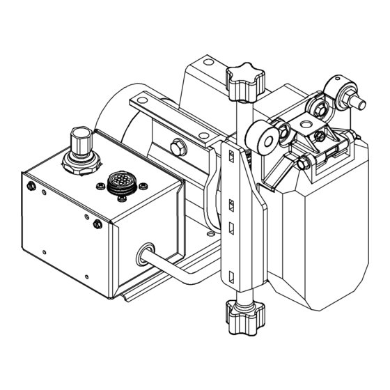
SECTION 8 − PARTS LIST See Table 8-1 For Hardware is common and not available unless listed. Drive Roll & Wire Guide Kits Dual Left Dual Right / Single Right Figure 8-1. Drive Assembly, Wire OM-247517 Page 20... - Page 25 33 34 42 (Left) 64 (Right) 251255-F OM-247517 Page 21...
- Page 26 Item Dia. Part Description Quantity Mkgs. Figure 8-1. Drive Assembly, Wire ....010668 Screw, Cap Stl Sch .250-20 X 1.500 ....... .
- Page 27 Item Dia. Part Description Quantity Mkgs. Figure 8-1. Drive Assembly, Wire (Continued) ....250697 ..Plug Assy, Motor/Gas Box ........
- Page 28 Table 8-1. Drive Roll And Wire Guide Kits OM-247517 Page 24...
- Page 29 Notes Start Your Professional Over 80,000 trained 400 Trade Square East, Troy, Ohio 45373 Welding Career Now! since 1930! 1-800-332-9448 www.welding.org...
- Page 30 Notes...
- Page 31 Effective January 1, 2017 (Equipment with a serial number preface of MH or newer) This limited warranty supersedes all previous Miller warranties and is exclusive with no other guarantees or warranties expressed or implied. Warranty Questions? LIMITED WARRANTY − Subject to the terms and conditions below, 6 Months —...
- Page 32 Contact the Delivering Carrier to: File a claim for loss or damage during shipment. For assistance in filing or settling claims, contact your distributor and/or equipment manufacturer’s Transportation Department. © ORIGINAL INSTRUCTIONS − PRINTED IN USA 2017 Miller Electric Mfg. Co. 2017−01...