Table of Contents
Advertisement
Quick Links
Download this manual
See also:
Service Manual
Advertisement
Table of Contents

Related Manuals for Toro 44539


Summary of Contents for Toro 44539
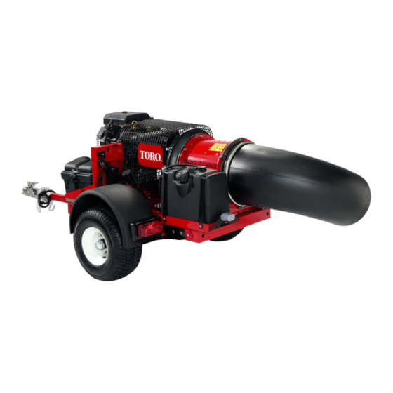
- Page 1 Form No. 3372-437 Rev A Road-Ready Pro Force Debris Blower Model No. 44539—Serial No. 313000001 and Up G020730 To register your product or download an Operator's Manual or Parts Catalog at no charge, go to www.Toro.com. Original Instructions (EN)
-
Page 2: Introduction
(2) this device must accept any interference that may be received, including You may contact Toro directly at www.Toro.com for interference that may cause undesirable operation. product and accessory information, help finding a dealer, This equipment generates and uses radio frequency energy and or to register your product. -
Page 3: Table Of Contents
Contents This manual identifies potential hazards and has safety messages identified by the safety alert symbol (Figure 2), which signals a hazard that may cause serious injury Introduction..............2 or death if you do not follow the recommended Safety ................4 precautions. -
Page 4: Safety
Safety • Use extra care when handling gasoline and other fuels. They are flammable and vapors are explosive. – Use only an approved container Hazard control and accident prevention are dependent upon the awareness, concern, and – Never refuel or drain the machine indoors. proper training of the personnel involved in the –... - Page 5 – Before backing up, look to the rear and ensure This will prevent accidental operation of the that no one is behind the machine. controlled machinery. – Watch out for traffic when near or crossing roads. • Power can be removed from the Base Unit by Always yield the right-of-way.
-
Page 6: Maintenance And Storage
Replace all worn or damaged decals. Maintenance and Storage • Use only Toro approved attachments. Warranty may • Let engine cool before storing and do not store near be voided if used with unapproved attachments. flame. -
Page 7: Safety And Instructional Decals
Safety and Instructional Decals Safety decals and instructions are easily visible to the operator and are located near any area of potential danger. Replace any decal that is damaged or lost. 115-5113 1. Warning—read the Operator's Manual, wear hearing and eye protection. -
Page 8: Setup
Setup Loose Parts Use the chart below to verify that all parts have been shipped. Procedure Description Qty. Petroleum jelly (not supplied) Connect the battery Debris blower assembly Hitch Mount the hitch to the debris blower Bolt (3/8 x 3 inches) Flange nut (3/8 inch) Connect the debris blower to the tow –... -
Page 9: Connecting The Battery
WARNING Incorrect battery cable routing could damage the blower and cables causing sparks. Sparks can cause the battery gasses to explode, Connecting the Battery resulting in personal injury. • Always disconnect the negative (black) Parts needed for this procedure: battery cable before disconnecting the positive (red) cable. -
Page 10: Mounting The Hitch To The Debris Blower
Mounting the Hitch to the Debris Blower Parts needed for this procedure: Debris blower assembly G020732 Hitch Bolt (3/8 x 3 inches) Figure 7 Flange nut (3/8 inch) 1. Wire harness 2. Harness clips Procedure 4. Plug the harness clips into the holes in the side of 1. -
Page 11: Product Overview
Product Overview Controls Engine Stop Press the Engine Stop button to stop the engine (Figure 9). Figure 8 1. Tongue 4. Safety chains 2. Ball socket 5. Locking pin 3. Coupler lever, locked 6. Hitch tube holster position 3. Close the coupler lever making sure it is securely locked. -
Page 12: Choke Control
position. To shut engine off, rotate key counterclockwise to the OFF position. Choke Control To start a cold engine, move the choke control lever (Figure 10) to the ON position. G020713 Figure 10 1. Choke control 3. Hour meter 2. Ignition switch Hour Meter The hour meter (Figure 10) indicates the total hours of machine operation. -
Page 13: Operation
Operation • Do Not use gasoline containing methanol. • Do Not store fuel either in the fuel tank or fuel Note: Determine the left and right sides of the containers over the winter unless a fuel stabilizer is machine from the normal operating position. used. -
Page 14: Checking The Engine Oil Level
Add the correct amount of gas stabilizer/conditioner DANGER to the gas. In certain conditions during fueling, static Note: A fuel stabilizer/conditioner is most effective electricity can be released causing a spark which when mixed with fresh gasoline. To minimize the can ignite the gasoline vapors. -
Page 15: Checking The Torque Of The Wheel Lug Nuts
3. Rotate the engine ignition key to the “START” position and quickly release it to the “ON” position (Figure 14). This wakes up the receiver . Note: If the key was left in the on position for an extended time, move the key to the off position before proceeding to the starting procedure. -
Page 16: Start, Stop And Inactivity Time Out
length of time that the Start Relay Control can 2. Let the engine idle for 20 seconds. be active is 25 seconds from pressing the Rotate 3. Press the STOP button on the remote control. Right button. The Start button can be pressed 4. -
Page 17: Adjusting The Nozzle Direction
• To wake controller in time-out mode, turn the key • ALWAYS make sure the blower is equipped with switch to the OFF position and then turn the key the "Safety Chains”. switch to the start position momentarily (engine will •... -
Page 18: Operating Tips
hitch ball on the towing vehicle securely and make • Before backing up, look to the rear and ensure that sure the lock lever is in the down position (locked). no one is behind the machine. • Do not run the engine in or direct the blower nozzle CAUTION into a confined area without adequate ventilation. -
Page 19: Maintenance
Maintenance Recommended Maintenance Schedule(s) Maintenance Service Maintenance Procedure Interval • Check condition and tension of belt After the first 8 hours • Check the torque of the wheel lug nuts After the first 10 hours • Check the engine oil level. •... -
Page 20: Daily Maintenance Checklist
Daily Maintenance Checklist Duplicate this page for routine use. Maintenance Check Item For the week of: Mon. Tues. Wed. Thurs. Fri. Sat. Sun. Check the instrument operation Check the fuel level. Check the engine oil level. Clean the engine air cooling fins. -
Page 21: Servicing The Air Cleaner
Servicing the Air Cleaner 1. Wash the foam pre-filter in liquid soap and warm water. When clean, rinse it thoroughly. Service Interval: Every 25 hours—Clean the foam air 2. Dry the pre-filter by squeezing it in a clean cloth (do filter element and check the paper not wring). -
Page 22: Servicing The Carbon Canister
Servicing the Carbon Canister Replacing the Carbon Canister Air Filter Service Interval: Every 200 hours 1. Stop the engine, remove the key, and wait for all moving parts to stop before leaving the operating position. 2. Disconnect the hose from the carbon canister air filter (Figure 21). - Page 23 Checking the Engine Oil Level 4. Place a pan below the drain. Rotate oil drain valve to allow oil to drain (Figure 25). Service Interval: Before each use or daily Note: A hose may be inserted onto the drain valve Note: The best time to check the engine oil is when the to direct the oil flow.
-
Page 24: Associate Remote Control And Base Unit
Note: If the flashing LINK LED goes solid, the Association procedure is aborted and must be started anew to establish the communication link. 5. When the LINK LED flashes Amber, release the two buttons. All three LEDs flash allowing two (2) seconds for the operator to perform the next step. -
Page 25: Servicing The Spark Plugs
Servicing the Spark Plugs Ensure that the air gap between the center and side electrodes is correct before installing the spark plug. Use a spark plug wrench for removing and installing the spark plugs and a gapping tool/feeler gauge to check and adjust the air gap. -
Page 26: Servicing The Fuel Tank
Cleaning the Engine Screen and the Oil Cooler Service Interval: Before each use or daily Before each use, check and clean the engine screen and oil cooler. Remove any build up of grass, dirt or other debris from the oil cooler and engine screen (Figure 31). Figure 30 1. -
Page 27: Adjusting The Belt
Inspecting the Tires Service Interval: Every 100 hours Operating accidents can damage a tire or rim, so inspect tire condition after an accident. Check the tire pressure frequently to ensure proper inflation. If the tires are not inflated to the correct pressure, the tires will wear prematurely. -
Page 28: Electrical Maintenance
Electrical Maintenance 2. Connect a 3 to 4 amp battery charger to the battery posts (Figure 39). Charge the battery at a rate of 3 to Important: Before welding on the machine, 4 amperes for 4 to 8 hours. disconnect the controller and the negative cable from the battery to prevent damage to the electrical system. -
Page 29: Waste Disposal
Storage over-tightened, but they should be tight enough to assure the gasket provides a proper seal. 1. Turn the key to off. Remove spark plug wire. Note: Be sure to observe proper polarity when Remove the key. placing batteries in the remote control battery 2. - Page 30 10. Paint all scratched or bare metal surfaces. Paint is available from your Authorized Service Dealer. 11. Store the machine in a clean, dry garage or storage area. Remove the key from the ignition switch and keep it out of reach of children or other unauthorized users.
-
Page 31: Schematics
Schematics g018513 Electrical Schematic (Rev. -) - Page 32 Countries Other than the United States or Canada Customers who have purchased Toro products exported from the United States or Canada should contact their Toro Distributor (Dealer) to obtain guarantee policies for your country, province, or state. If for any reason you are dissatisfied with your Distributor's service or have difficulty obtaining guarantee information, contact the Toro importer.