
Related Manuals for Toro Road-Ready Pro Force


Summary of Contents for Toro Road-Ready Pro Force
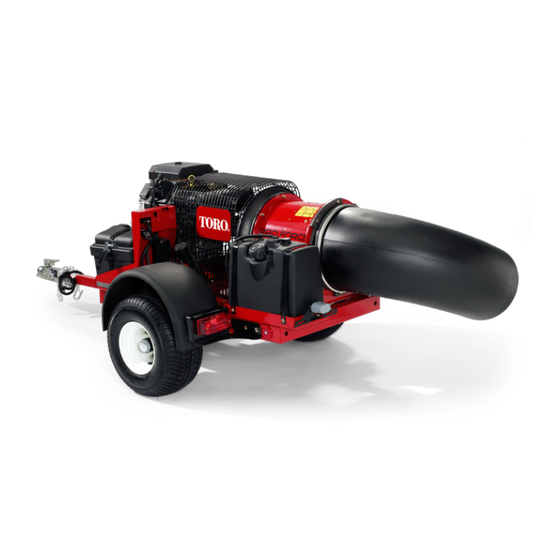
- Page 1 Form No. 3380-608 Rev A Road-Ready Pro Force Debris Blower Model No. 44539—Serial No. 314000001 and Up G020730 *3380-608* A Register at www.Toro.com. Original Instructions (EN)
-
Page 2: Introduction
You are responsible for operating the product properly and safely. Electromagnetic Compatibility You may contact Toro directly at www.Toro.com for product Domestic: This device complies with FCC rules Part 15. Operation is subject to the following two conditions: (1) This... -
Page 3: Table Of Contents
Contents which signals a hazard that may cause serious injury or death if you do not follow the recommended precautions. Introduction ..............2 Safety ................4 Safe Operating Practices........... 4 Safety and Instructional Decals ......... 7 Figure 2 Setup ................8 1. -
Page 4: Safety
Safe handling of fuels Safety • To avoid personal injury or property damage, use extreme care in handling gasoline. Gasoline is extremely Hazard control and accident prevention are dependent flammable and the vapors are explosive. upon the awareness, concern, and proper training of the personnel involved in the operation, transport, •... - Page 5 • • Using the machine demands attention. To prevent loss Make sure that the machinery and surrounding area is of control: clear before operating. Do not activate the remote control system until certain that it is safe to do so. –...
- Page 6 • Keep all parts in good working condition and all hardware tightened. Replace all worn or damaged decals. • Use only Toro approved attachments. Warranty may be voided if used with unapproved attachments. Hauling • Use care when loading or unloading the machine into a...
-
Page 7: Safety And Instructional Decals
Safety and Instructional Decals Safety decals and instructions are easily visible to the operator and are located near any area of potential danger. Replace any decal that is damaged or lost. 115-5105 1. Warning—read the Operator's Manual. 2. Warning—do not operate this machine unless you are trained. 3. -
Page 8: Setup
Setup Loose Parts Use the chart below to verify that all parts have been shipped. Procedure Description Qty. Petroleum jelly (not supplied) Connect the battery Debris blower assembly Hitch Mount the hitch to the debris blower Bolt (3/8 x 3 inches) Flange nut (3/8 inch) Connect the debris blower to the tow –... -
Page 9: Connecting The Battery
WARNING Incorrect battery cable routing could damage the blower and cables causing sparks. Sparks can cause the battery gasses to explode, Connecting the Battery resulting in personal injury. • Always disconnect the negative (black) Parts needed for this procedure: battery cable before disconnecting the positive (red) cable. -
Page 10: Mounting The Hitch To The Debris Blower
Mounting the Hitch to the Debris Blower Parts needed for this procedure: Debris blower assembly G020732 Hitch Bolt (3/8 x 3 inches) Figure 7 Flange nut (3/8 inch) 1. Wire harness 2. Harness clips Procedure 4. Plug the harness clips into the holes in the side of the 1. -
Page 11: Product Overview
Product Overview Controls Engine Stop Press the Engine Stop button to stop the engine (Figure 9). Figure 8 1. Tongue 4. Safety chains 2. Ball socket 5. Locking pin 3. Coupler lever, locked 6. Hitch tube holster position 3. Close the coupler lever making sure it is securely locked. 4. -
Page 12: Operation
Choke Control Operation To start a cold engine, move the choke control lever (Figure Note: Determine the left and right sides of the machine 10) to the ON position. from the normal operating position. Attaching the Trailer This trailer uses a coupler that requires a 2 inch ball for the hitch. - Page 13 problems and/or engine damage which may not be DANGER covered under warranty. In certain conditions during fueling, static – Do not use gasoline containing methanol. electricity can be released causing a spark which can ignite the gasoline vapors. A fire or explosion –...
-
Page 14: Checking The Engine Oil Level
Filling the Fuel Tank Checking the Torque of the 1. Shut the engine off. Wheel Lug Nuts 2. Clean the area around the fuel tank cap and remove Service Interval: After the first 10 hours the cap (Figure 12). Check the torque of the wheel lug nuts initially and after the Note: The fuel tank cap contains a gauge which shows first 10 hours of operation. - Page 15 Rotate Right and Left buttons will return to control the Chute Motor. G020713 Figure 14 1. Ignition switch 3. Hour meter 2. Choke control 4. Engine Start will only become energized by pressing the Start button while the Engine Start Enable Condition is active.
-
Page 16: Start, Stop And Inactivity Time Out
Start, Stop and Inactivity Time Adjusting the Nozzle Direction The direction of the nozzle opening can be changed from right to left by pressing the appropriate button on the remote The remote control activates (powers up) when any push control (Figure 17). button is pressed. -
Page 17: Debris Blower To Tow Vehicle Connection
Operating Tips • Remember in most cases the maximum speed unless otherwise posted for highway towing is 55 MPH, however before towing the debris blower, check your local state, WARNING and county vehicle towing requirements. Recommended Discharged air has considerable force and could off road towing is not to exceed 15 MPH or less cause injury or loss of footing. - Page 18 • If the tow vehicle engine stalls or the machine loses headway and cannot make it to the top of a slope, do not turn the machine around. Always back the tow vehicle slowly straight down the slope. • Do not take an injury risk! When a person or pet appears unexpectedly in or near the operating area, stop operation.
-
Page 19: Maintenance
Maintenance Note: Looking for an Electrical Schematic or Hydraulic Schematic for your machine? Download a free copy of the schematic by visiting www.Toro.com and searching for your machine from the Manuals link on the home page. Recommended Maintenance Schedule(s) Maintenance Service... -
Page 20: Daily Maintenance Checklist
Daily Maintenance Checklist Duplicate this page for routine use. Maintenance Check Item For the week of: Mon. Tues. Wed. Thurs. Fri. Sat. Sun. Check the instrument operation Check the fuel level. Check the engine oil level. Clean the engine air cooling fins. -
Page 21: Servicing The Air Cleaner
Servicing the Air Cleaner 2. Dry the pre-filter by squeezing it in a clean cloth (do not wring). Service Interval: Every 25 hours—Clean the foam air filter 3. Put one or two ounces of oil on the pre-filter (Figure element and check the paper element for 19). -
Page 22: Servicing The Carbon Canister
Servicing the Carbon Canister Replacing the Carbon Canister Air Filter Service Interval: Every 200 hours 1. Stop the engine, remove the key, and wait for all moving parts to stop before leaving the operating position. 2. Disconnect the hose from the carbon canister air filter (Figure 21). - Page 23 Checking the Engine Oil Level Note: A hose may be inserted onto the drain valve to direct the oil flow. Service Interval: Before each use or daily 5. When oil has drained completely, close the drain valve. Note: The best time to check the engine oil is when the Note: Dispose of the used oil at a recycling center.
-
Page 24: Associate Remote Control And Base Unit
4. Install the replacement oil filter to the filter adapter, Once the process is complete, the Amber LINK LED turn the oil filter clockwise until the rubber gasket remains solid, the RX LED stops flashing Red and the contacts the filter adapter, then tighten the filter an TX LED lights steady Green (button being held) until additional 2/3 to 1 turn (Figure 26). -
Page 25: Replacing The Fuel Filter
Replacing the Fuel Filter Service Interval: Every 500 hours Never install a dirty filter if it is removed from the fuel line. 1. Stop the engine, remove the key, and wait for all moving parts to stop before leaving the operating position. 2. -
Page 26: Cleaning The Engine Screen And The Oil Cooler
Cleaning the Nozzle Guides Note: This is the best time to install a new fuel filter because the fuel tank is empty. Check and remove any grass, dirt or debris buildup around 5. Install the fuel line onto the fuel filter. Slide the hose and in between the nozzle guides (Figure 33). -
Page 27: Inspecting The Tires
2. Pivot the pulley mounting bracket away from the nozzle until the desired belt tension attained. 3. Tighten the mounting bolts. Inspecting the Tires Service Interval: Every 100 hours Operating accidents can damage a tire or rim, so inspect tire Figure 37 condition after an accident. - Page 28 1. Remove the four small Phillips screws from the Battery Compartment cover and lift the cover from the remote control. 2. If installing batteries in an empty battery compartment, install three fresh size AAA batteries. Be sure to position the batteries as shown in Figure 40. 3.
-
Page 29: Waste Disposal
Fusible Link removed from the engine, pour two tablespoons of engine oil into the spark plug hole. Now use the starter A fusible link is incorporated into the machines wiring. It is a to crank the engine and distribute the oil inside the grey wire located below the in line fuse. - Page 30 Notes:...
- Page 31 Notes:...
- Page 32 Countries Other than the United States or Canada Customers who have purchased Toro products exported from the United States or Canada should contact their Toro Distributor (Dealer) to obtain guarantee policies for your country, province, or state. If for any reason you are dissatisfied with your Distributor's service or have difficulty obtaining guarantee information, contact the Toro importer.