Table of Contents

Related Manuals for Toro Pro Force


Summary of Contents for Toro Pro Force
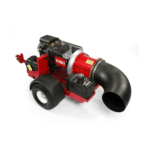
- Page 1 Form No. 3373-738 Rev A Pro Force Debris Blower Model No. 44542—Serial No. 312000110 and Up To register your product or download an Operator's Manual or Parts Catalog at no charge, go to www.Toro.com. Original Instructions (EN)
-
Page 2: Introduction
You may contact Toro directly at www.Toro.com for This equipment generates and uses radio frequency energy and product and accessory information, help finding a dealer, if not installed and used properly, that is, in strict accordance or to register your product. -
Page 3: Table Of Contents
Contents Model No. Introduction..............2 Serial No. Safety ................4 Safe Operating Practices ........4 Safety and Instructional Decals ......6 This manual identifies potential hazards and has safety Setup ................7 messages identified by the safety alert symbol (Figure 2), 1 Remove, Activate and Charge Battery .... -
Page 4: Safety
Safety • Use extra care when handling gasoline and other fuels. They are flammable and vapors are explosive. Hazard control and accident prevention are – Use only an approved container dependent upon the awareness, concern, and – Never refuel or drain the machine indoors. proper training of the personnel involved in the –... - Page 5 • Let engine cool before storing and do not store near flame. • Use only Toro approved attachments. Warranty may be voided if used with unapproved attachments. • Shut off fuel while storing or transporting. Do not store fuel near flames or drain indoors.
-
Page 6: Safety And Instructional Decals
Safety and Instructional Decals Safety decals and instructions are easily visible to the operator and are located near any area of potential danger. Replace any decal that is damaged or lost. 115-5106 1. Warning—read the Operator's Manual. 2. Thrown object hazard—keep bystanders a safe distance from the machine. -
Page 7: Setup
Setup Loose Parts Use the chart below to verify that all parts have been shipped. Procedure Description Qty. Electrolyte (not supplied) Charge the battery Petroleum jelly (not supplied) Install the battery Debris blower assembly Hitch Bolt (3/8 x 3 inches) Flange nut (3/8 inch) Mount the hitch to the debris blower Hitch clevis... -
Page 8: Remove, Activate And Charge Battery
2. Remove the strap securing the battery cover to the battery box (Figure 3). Remove, Activate and Charge Battery Parts needed for this procedure: Electrolyte (not supplied) Procedure 1. If the battery is not filled with electrolyte or activated, bulk electrolyte with 1.260 specific gravity must be purchased from a local battery supply outlet and added to the battery. -
Page 9: Install The Battery
WARNING Charging the battery produces gasses that can explode. Never smoke near the battery and keep sparks and flames away from battery. 8. After charging, remove the vent caps and check the electrolyte level. 9. If needed, fill each cell to the proper level (Figure 4). 10. -
Page 10: Mounting The Hitch To The Debris Blower
Figure 7 1. Frame brackets 3. Hitch clevis 2. Hitch tube Figure 6 Note: The hitch tube can be rotated 180 degrees to 1. Battery box 4. Positive battery post accommodate different hitch heights. 2. Negative battery post 5. Battery strap 3. - Page 11 • Remove the bolts and nuts securing the hitch tube to frame brackets (Figure 7). • Secure the tube to the frame with the bolts and flange nuts. 4. Connect the blower clevis hitch to the tow vehicle hitch with the hitch pin and clevis (Figure 8). Figure 8 1.
-
Page 12: Product Overview
Product Overview Controls Engine Stop Press the Engine Stop button to stop the engine (Figure 9). Figure 10 1. Ignition switch 3. Hour meter 2. Choke control Figure 9 Hour Meter 1. Nozzle direction, right 4. Nozzle direction, left 2. Engine stop 5. -
Page 13: Operation
Operation DANGER In certain conditions during fueling, static Note: Determine the left and right sides of the electricity can be released causing a spark which machine from the normal operating position. can ignite the gasoline vapors. A fire or explosion from gasoline can burn you and others and can damage property. -
Page 14: Checking The Engine Oil Level
Note: A fuel stabilizer/conditioner is most effective when mixed with fresh gasoline. To minimize the chance of varnish deposits in the fuel system, use fuel stabilizer at all times. Filling the Fuel Tank 1. Shut the engine off. 2. Clean the area around the fuel tank cap and remove the cap (Figure 11). -
Page 15: Controller Time Out
3. Rotate the engine ignition key to the “START” position and quickly release it to the “ON” position. This wakes up the receiver (Figure 13). Note: If the key was left in the on position for an extended time, move the key to the off position before proceeding to the starting procedure. -
Page 16: Operating Tips
• Use care when approaching blind corners, shrubs, trees, or other objects that may obscure vision. • Reduce your speed when making sharp turns and when turning on hillsides • Before backing up, look to the rear and ensure that no one is behind the machine. -
Page 17: Maintenance
Maintenance Recommended Maintenance Schedule(s) Maintenance Service Maintenance Procedure Interval • Check condition and tension of belt After the first 8 hours • Check the torque of the wheel lug nuts After the first 10 hours • Check the engine oil level. •... -
Page 18: Daily Maintenance Checklist
Daily Maintenance Checklist Duplicate this page for routine use. Maintenance Check Item For the week of: Mon. Tues. Wed. Thurs. Fri. Sat. Sun. Check the instrument operation Check the fuel level. Check the engine oil level. Clean the engine air cooling fins. -
Page 19: Servicing The Air Cleaner
Servicing the Air Cleaner 1. Wash the foam pre-filter in liquid soap and warm water. When clean, rinse it thoroughly. Service Interval: Every 25 hours—Clean the foam air 2. Dry the pre-filter by squeezing it in a clean cloth (do filter element and check the paper not wring). -
Page 20: Servicing The Carbon Canister Filters
Servicing the Carbon Canister Filters Replacing the Carbon Canister Air Filter Service Interval: Every 200 hours (Service more frequently if conditions are extremely dusty or sandy) 1. Stop the engine, remove the key, and wait for all moving parts to stop before leaving the operating position. - Page 21 Checking the Engine Oil Level 4. Place a pan below the drain. Rotate oil drain valve to allow oil to drain (Figure 22). Service Interval: Before each use or daily Note: A hose may be inserted onto the drain valve Note: The best time to check the engine oil is when the to direct the oil flow.
-
Page 22: Synchronize The Remote Transmitter/Control Module
Figure 23 1. Oil filter 3. Adapter 2. Adapter gasket Figure 24 1. Yellow with black stripe 3. Engine starter motor 3. Apply a thin coat of new oil to the rubber gasket on wire the replacement filter (Figure 23). 2. -
Page 23: Replacing The Fuel Filter
Important: Always replace the spark plugs 3. Squeeze the ends of the hose clamps together and when it has a black coating, worn electrodes, an slide them away from the filter (Figure 27). oily film, or cracks. 2. Check the gap between the center and side electrodes (Figure 25). -
Page 24: Cleaning The Engine Screen And The Oil Cooler
Cleaning the Engine Screen and the Oil Cooler Service Interval: Before each use or daily Before each use, check and clean the engine screen and oil cooler. Remove any build up of grass, dirt or other debris from the oil cooler and engine screen (Figure 28). Figure 28 1. -
Page 25: Waste Disposal
A. Add a petroleum based stabilizer/conditioner to fuel in the tank. Follow mixing instructions from stabilizer manufacture. Do not use an alcohol based stabilizer (ethanol or methanol). Note: A fuel stabilizer/conditioner is most effective when mixed with fresh gasoline and used at all times. -
Page 26: Schematics
Schematics g018594 Electrical Schematic (Rev. -) - Page 27 Notes:...
- Page 28 Countries Other than the United States or Canada Customers who have purchased Toro products exported from the United States or Canada should contact their Toro Distributor (Dealer) to obtain guarantee policies for your country, province, or state. If for any reason you are dissatisfied with your Distributor's service or have difficulty obtaining guarantee information, contact the Toro importer.