
Related Manuals for Toro 44538


Summary of Contents for Toro 44538
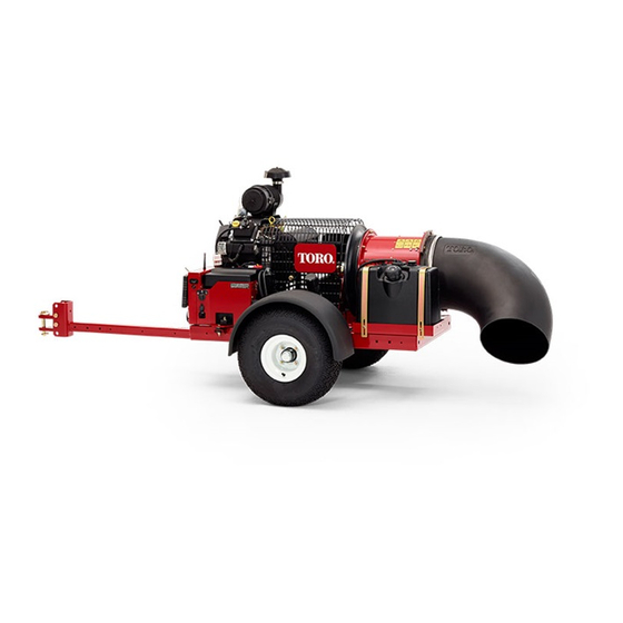
- Page 1 Form No. 3385-294 Rev C Pro Force Debris Blower Model No. 44538—Serial No. 314000001 and Up G020709 *3385-294* C Register at www.Toro.com. Original Instructions (EN)
- Page 2 Operation is subject to the following two conditions: (1) this device may not cause interference, and (2) this device must accept any interference, including interference that may cause undesired operation of the device. © 2014—The Toro® Company Contact us at www.Toro.com. 8111 Lyndale Avenue South Printed in the USA.
-
Page 3: Table Of Contents
2 Mounting the Hitch to the Debris Blower ....8 3 Connecting the Debris Blower to the Tow You may contact Toro directly at www.Toro.com for product Vehicle ............... 8 and accessory information, help finding a dealer, or to register Product Overview ............10... -
Page 4: Safety
Safe Handling Of Fuels Safety • To avoid personal injury or property damage, use extreme care in handling gasoline. Gasoline is extremely Hazard control and accident prevention are dependent flammable and the vapors are explosive. upon the awareness, concern, and proper training of the personnel involved in the operation, transport, •... -
Page 5: Maintenance And Storage
If major repairs are ever needed or assistance • Failure to abide by Safety Precautions may result in is desired, contact an Authorized Toro Distributor. equipment failure, loss of authority to operate the • To reduce a potential fire hazard, keep the engine free of equipment, and personal injury. -
Page 6: Safety And Instructional Decals
• Tie the machine down securely using straps, chains, cable, • Use only Toro approved attachments. Warranty may be or ropes. Both front and rear straps should be directed voided if used with unapproved attachments. down and outward from the machine. -
Page 7: Setup
Setup Loose Parts Use the chart below to verify that all parts have been shipped. Procedure Description Qty. Petroleum jelly (not supplied) Connect the battery Debris blower assembly Hitch Bolt (3/8 x 3 inches) Flange nut (3/8 inch) Mount the hitch to the debris blower Hitch clevis Bolt (5/8 x 4–1/2 inch) Lock nut (5/8 inch) -
Page 8: Mounting The Hitch To The Debris Blower
2. Insert the hitch tube into the frame brackets (Figure DANGER 4). Secure the tube to the frame with 2 bolts (3/8 x 3 Battery electrolyte contains sulfuric acid inches) and flange nuts (3/8 inch). which is a deadly poison and causes severe burns. - Page 9 • Remove the bolts and nuts securing the hitch tube to frame brackets (Figure 4). • Secure the tube to the frame with the bolts and flange nuts. 4. Connect the blower clevis hitch to the tow vehicle hitch with the hitch pin and clevis (Figure 5). Figure 5 1.
-
Page 10: Product Overview
Choke Control Product Overview To start a cold engine, move the choke control lever (Figure Controls 7) to the ON position. Engine Stop Press the Engine Stop button to stop the engine (Figure 6). G020713 Figure 7 1. Choke control 3. -
Page 11: Operation
Operation DANGER In certain conditions, gasoline is extremely Note: Determine the left and right sides of the machine flammable and highly explosive. A fire or explosion from the normal operating position. from gasoline can burn you and others and can damage property. -
Page 12: Checking The Engine Oil Level
This space in the tank allows gasoline to expand. Do WARNING not fill the fuel tanks completely full. Gasoline is harmful or fatal if swallowed. Long-term 4. Install fuel tank cap securely. exposure to vapors can cause serious injury and illness. -
Page 13: Starting And Stopping The Engine
Starting and Stopping the • Then, press the rotate right button. Engine • Then, press and hold the START button until the engine starts. Starting the Engine WARNING ROTATING PARTS CAN CAUSE SERIOUS PERSONAL INJURY • Keep hands and feet away from the machine when it is running. -
Page 14: Start, Stop And Inactivity Time Out
Note: If the sequence is aborted or the Engine Start Enable Condition expires, normal functionality of the Rotate Right and Left buttons will return to control the Chute Motor. Important: Do not engage starter for more than 10 seconds at a time. If engine fails to start allow 30 second cool-down period between attempts. -
Page 15: Adjusting The Nozzle Direction
Adjusting the Nozzle Direction DANGER TIP OVER CAN CAUSE SERIOUS INJURY OR The direction of the nozzle opening can be changed from DEATH. right to left by pressing the appropriate button on the remote control (Figure 13). • NEVER operate on steep slopes. •... - Page 16 • Do not exceed 20 mph when transporting blower. • Do not touch the engine or muffler while the engine is running or soon after it is stopped. These areas could be hot enough to cause a burn. Important: Raise the nozzle before transporting the blower.
-
Page 17: Maintenance
Maintenance Recommended Maintenance Schedule(s) Maintenance Service Maintenance Procedure Interval • Check the condition and the tension of the belt After the first 8 hours • Check the torque of the wheel lug nuts After the first 10 hours • Check the engine oil level. •... -
Page 18: Daily Maintenance Checklist
Daily Maintenance Checklist Duplicate this page for routine use. Maintenance Check Item For the week of: Mon. Tues. Wed. Thurs. Fri. Sat. Sun. Check the instrument operation Check the fuel level. Check the engine oil level. Clean the engine air cooling fins. -
Page 19: Servicing The Air Cleaner
Servicing the Air Cleaner 2. Dry the pre filter by squeezing it in a clean cloth (do not wring). Service Interval: Every 25 hours—Clean the foam air filter 3. Put one or two ounces (29.6 or 59.1 ml) of oil on the element and check the paper element for pre filter (Figure 15). -
Page 20: Servicing The Carbon Canister
Servicing the Carbon Canister Replacing the Carbon Canister Air Filter Service Interval: Every 200 hours 1. Stop the engine, remove the key, and wait for all moving parts to stop before leaving the operating position. 2. Remove and discard the carbon canister air filter (Figure 17). - Page 21 Checking the Engine Oil Level Note: A hose may be inserted onto the drain valve to direct the oil flow. The hose is not included with the Service Interval: Before each use or daily machine. Note: The best time to check the engine oil is when the 5.
-
Page 22: Associate Remote Control And Base Unit
3. Apply a thin coat of new oil to the rubber gasket on Once the process is complete, the Amber LINK LED the replacement filter (Figure 22). remains solid, the RX LED stops flashing Red and the TX LED lights steady Green (button being held) until 4. -
Page 23: Replacing The Fuel Filter
Replacing the Fuel Filter Service Interval: Every 500 hours Never install a dirty filter if it is removed from the fuel line. 1. Stop the engine, remove the key, and wait for all moving parts to stop before leaving the operating position. 2. -
Page 24: Cleaning The Engine Screen And The Oil Cooler
Cleaning the Nozzle Guides Note: This is the best time to install a new fuel filter because the fuel tank is empty. Check and remove any grass, dirt or debris buildup around 5. Install the fuel line onto the fuel filter. Slide the hose and in between the nozzle guides (Figure 29). -
Page 25: Electrical Maintenance
over-tightened, but they should be tight enough to assure the gasket provides a proper seal. Note: Be sure to observe proper polarity when placing batteries in the remote control battery compartment. g017703 Figure 31 1. Cover screw 2. Sealing gasket Fuses G015845 Figure 30... -
Page 26: Storage
Storage out of reach of children or other unauthorized users. Cover the machine to protect it and keep it clean. 1. Turn the key to off. Remove spark plug wire. Remove the key. Waste Disposal 2. Remove grass clippings, dirt, and grime from the external parts of the entire machine, especially the Engine oil, engine and remote control batteries are pollutants engine. - Page 27 Notes:...
- Page 28 Countries Other than the United States or Canada Customers who have purchased Toro products exported from the United States or Canada should contact their Toro Distributor (Dealer) to obtain guarantee policies for your country, province, or state. If for any reason you are dissatisfied with your Distributor's service or have difficulty obtaining guarantee information, contact the Toro importer.