Table of Contents
Advertisement
Quick Links
Preface
The purpose of this publication is to provide the service
technician with information for troubleshooting, testing
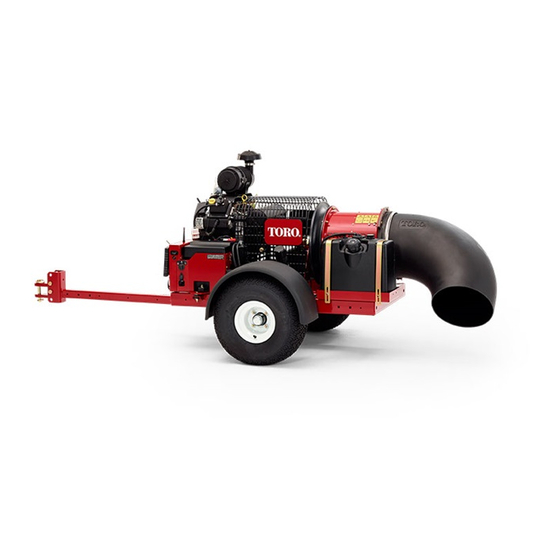
and repair of major systems and components on the
ProForce Debris Blower.
REFER TO THE OPERATOR'S MANUALS FOR OP-
ERATING, MAINTENANCE AND ADJUSTMENT
INSTRUCTIONS. Space is provided in Chapter 2 of this
book to insert the Operator's Manuals and Parts Cata-
logs for your machine. Additional copies of the Opera-
tor's Manual are available on the Internet at
www.Toro.com.
The Toro Company reserves the right to change product
specifications or this publication without notice.
ProForce
E The Toro Company - - 2008, 2009, 2011, 2014
Service Manual
Debris Blower
R
This safety symbol means DANGER, WARNING,
or CAUTION, PERSONAL SAFETY INSTRUC-
TION. When you see this symbol, carefully read
the instructions that follow. Failure to obey the
instructions may result in personal injury.
NOTE: A NOTE will give general information about the
correct operation, maintenance, service, testing or re-
pair of the machine.
IMPORTANT: The IMPORTANT notice will give im-
portant instructions which must be followed to pre-
vent damage to systems or components on the
machine.
Part No. 08158SL (Rev. C)
Advertisement
Chapters
Table of Contents

Related Manuals for Toro ProForce 44538


Summary of Contents for Toro ProForce 44538
- Page 1 IMPORTANT: The IMPORTANT notice will give im- portant instructions which must be followed to pre- vent damage to systems or components on the machine. E The Toro Company - - 2008, 2009, 2011, 2014...
- Page 2 This page is intentionally blank. ProForce Debris Blower...
-
Page 3: Table Of Contents
Table Of Contents Chapter 1 - Safety Chapter 5 - Blower Assembly Safety Instructions ......1 - 2 General Information . - Page 4 This page is intentionally blank. ProForce Debris Blower...
- Page 5 Chapter 1 Safety Table of Contents SAFETY INSTRUCTIONS ..... . Before Operating ......While Operating .
-
Page 6: Safety Instructions
4. Make sure that operator is familiar with safe tow ve- Operator’s Manual are available on the internet at hicle operation. www.Toro.com. 5. Tighten any loose nuts, bolts, screws or other fasten- 2. Keep all shields, safety devices and decals in place. -
Page 7: While Operating
While Operating 1. Operator should be on the tow vehicle when starting 7. While operating, the combination of the tow vehicle the engine and when operating the ProForce Debris and the ProForce Debris Blower may exceed noise lev- Blower. Stay away from the blower when it is engaged. els of 85dB(A) at the operator position. -
Page 8: Maintenance And Service
Debris Blower. Keep bystanders away. performance and continued safety certification of the 8. Do not overspeed the engine by changing governor machine, use genuine Toro replacement parts and ac- setting. To assure safety and accuracy, check maximum cessories. Replacement parts and accessories made engine speed with a tachometer. -
Page 9: Securing Proforce Debris Blower To Tow Vehicle
Securing ProForce Debris Blower to Tow Vehicle While operating or servicing the ProForce Debris Blow- er, make sure that blower is properly secured to tow ve- hicle (Fig. 1). Refer to your Operator’s Manual for the correct procedure for attaching blower to tow vehicle. Figure 1 1. -
Page 10: Safety And Instruction Decals
ProForce Debris Blower. If any decal becomes illeg- ible or damaged, install a new decal. Part numbers for replacement decals are listed in your Parts Catalog. Or- der replacement decals from your Authorized Toro Dis- tributor. Safety Page 1 - - 6... -
Page 11: Product Records
Chapter 2 Product Records and Maintenance Table of Contents PRODUCT RECORDS ......MAINTENANCE ....... EQUIVALENTS AND CONVERSIONS . -
Page 12: Equivalents And Conversions
Equivalents and Conversions 0.09375 Product Records and Maintenance Page 2 - - 2 ProForce Debris Blower... -
Page 13: Torque Specifications
For critical applications, as determined reduced by 25% for lubricated fasteners to achieve by Toro, either the recommended torque or a torque that the similar stress as a dry fastener. Torque values may is unique to the application is clearly identified and spe- also have to be reduced when the fastener is threaded cified in this Service Manual. - Page 14 Standard Torque for Dry, Zinc Plated and Steel Fasteners (Inch Series) Grade 1, 5 & SAE Grade 1 Bolts, Screws, Studs & SAE Grade 5 Bolts, Screws, Studs & SAE Grade 8 Bolts, Screws, Studs & Thread Size 8 with Thin Sems with Regular Height Nuts Sems with Regular Height Nuts Sems with Regular Height Nuts...
- Page 15 Standard Torque for Dry, Zinc Plated and Steel Fasteners (Metric Fasteners) Class 8.8 Bolts, Screws and Studs with Class 10.9 Bolts, Screws and Studs with Thread Size Thread Size Regular Height Nuts Regular Height Nuts Regular Height Nuts Regular Height Nuts (Class 8 or Stronger Nuts) (Class 10 or Stronger Nuts) M5 X 0.8...
-
Page 16: Specifications
Other Torque Specifications SAE Grade 8 Steel Set Screws Wheel Bolts and Lug Nuts Recommended Torque Thread Size Recommended Torque** Thread Size Thread Size Square Head Hex Socket 7/16 -- 20 UNF 65 + 10 ft--lb 88 + 14 N--m Grade 5 1/4 -- 20 UNC 140 + 20 in--lb... -
Page 17: General Information
Chapter 3 Engine Table of Contents SPECIFICATIONS ......GENERAL INFORMATION ..... Operator’s Manual . -
Page 18: Specifications
Specifications Item Description Make / Designation Kohler, 4--cycle, V--Twin cylinder, OHV, air cooled, Model CH740S Bore x Stroke 3.27 in x 2.64 in (83 mm x 67 mm) Total Displacement 44 in (725 cc) Compression Ratio 9.0:1 Governor Electronic Low Idle Speed (no load) 1800 + 100 RPM High Idle Speed (no load) 3450 + 100 RPM... -
Page 19: General Information
Special through your local Toro distributor. Be prepared to pro- tools are described in the KOHLER COMMAND EN- vide your distributor with the Toro model and serial num- GINE SERVICE MANUAL that is included at the end of ber. - Page 20 This page is intentionally blank. Engine Page 3 - - 4 ProForce Debris Blower...
-
Page 21: Service And Repairs
Service and Repairs Engine Cooling System To ensure proper engine cooling, make sure the grass screen, cooling fins and other external surfaces of the engine are kept clean at all times. IMPORTANT: The engine that powers the ProForce Debris Blower is air- -cooled. Operating the engine with dirty or plugged cooling fins or a plugged or dirty blower housing will result in engine overheat- ing and damage. -
Page 22: Fuel Tank
Fuel Tank RIGHT FRONT SERIAL NUMBER BELOW 310000000 SHOWN Figure 2 1. Frame 4. Felt strip (2 used) 7. Fuel cap and gauge 2. Foam strip (2 used) 5. Flange nut (4 used) 8. Worm clamp 3. Fuel tank 6. Tank strap (2 used) 9. - Page 23 Fuel Tank Removal (Figs. 2 and 4) 1. Park machine on a level surface with the engine OFF. Chock wheels to prevent machine from moving. 2. To prevent unexpected machine operation, discon- nect the negative battery cable from the battery terminal (see Battery Service in the Service and Repairs section of Chapter 4 -- Electrical System).
-
Page 24: Engine
Engine RIGHT FRONT 270 to 330 in- -lb (31 to 37 N- -m) Figure 6 1. Frame 3. Fuel tank 5. Flange head screw (4 used) 2. Engine 4. Flange nut (4 used) 6. Blower coupler assembly Engine Page 3 - - 8 ProForce Debris Blower... -
Page 25: Engine Removal
Engine Removal (Fig. 6) IMPORTANT: Make sure to not damage the engine, fuel hoses, electrical harness or other parts while 1. Park machine on a level surface with the engine not removing the engine. running and the ignition key removed from the key switch. -
Page 26: Engine Installation
Engine Installation (Fig. 6) 9. Connect wire harness connectors to engine. 1. Position machine on a level surface. A. Connect positive battery cable and fusible link to the starter motor B+ stud. 2. Make sure that all parts removed from the engine during maintenance or rebuilding are properly installed B. - Page 27 This page is intentionally blank. ProForce Debris Blower Page 3 - - 11 Engine Rev. C...
-
Page 28: Fuel Evaporative Control System (Serial Number Above 310000000)
Fuel Evaporative Control System (Serial Number Above 310000000) CHECK TO ENGINE VALVE FITTING CARBON FUEL CANISTER TANK FRESH AIR FILTER FILTER ENGINE Figure 11 ProForce blowers with serial number above 310000000 NOTE: If there is restriction in the fresh air filter, the car- are equipped with a fuel evaporative control system bon canister or the fuel vent valve, the fuel tank may dis- (EVAP) designed to collect and store evaporative emis-... - Page 29 Disassembly DANGER Gasoline is flammable. Use caution when storing or handling it. Wipe up any spilled fuel before starting the engine. 1. Inspect carbon canister and attached hoses for dam- age or obvious leaks. A damaged or leaking canister should be replaced. 2.
- Page 30 This page is intentionally blank. Engine Page 3 - - 14 ProForce Debris Blower Rev. C...
- Page 31 Chapter 4 Electrical System Table of Contents GENERAL INFORMATION ..... Operator’s Manual ......Electrical Power .
-
Page 32: General Information
General Information This Chapter gives information about troubleshooting, testing and repair of the electrical system used in the ProForce Debris Blower. Operator’s Manual The Operator’s Manual provides information regarding the operation, general maintenance and maintenance intervals for your ProForce Debris Blower machine. Re- fer to the Operator’s Manual for additional information when servicing the machine. -
Page 33: Special Tools
The multimeter can test electrical components and cir- cuits for current (amps), resistance (ohms) or voltage. Obtain this tool locally. NOTE: Toro recommends the use of a DIGITAL Volt-- Ohm--Amp multimeter when testing electrical circuits. The high impedance (internal resistance) of a digital me- ter in the voltage mode will make sure that excess cur- rent is not allowed through the meter. - Page 34 Battery Hydrometer Use the battery hydrometer when measuring specific gravity of battery electrolyte. Obtain this tool locally. Figure 4 Page 4 - - 4 Electrical System ProForce Debris Blower...
-
Page 35: Troubleshooting
Troubleshooting For effective troubleshooting and repairs, there must be CAUTION a good understanding of the electrical circuits (see Chapter 7 -- Electrical Diagrams) and components used on this machine. Remove all jewelry, especially rings and watches, before doing any electrical trouble- shooting or testing. - Page 36 Starting Problems (Continued) Problem Possible Causes Engine cranks, but does not start. Ignition switch is faulty. Magneto relay or circuit wiring is faulty. Fuel relay or circuit wiring is faulty. Diode is faulty. Operator remote control or remote control module is faulty.
-
Page 37: General Run Problems
General Run Problems Problem Possible Causes Battery does not charge. Wiring to charging circuit components is loose, corroded or damaged (see Electrical Schematic in Chapter 7 -- Electrical Diagrams). Voltage regulator is not properly grounded to engine. Voltage regulator is faulty. Ignition switch is faulty. -
Page 38: Electrical System Quick Checks
Electrical System Quick Checks Battery Test (Open Circuit Test) Use a digital multimeter to measure the battery voltage. Voltage Measured Battery Charge Level 12.68 volts Fully charged (100%) Set the multimeter to the DC volts setting. The battery should be at a temperature of 60 to 100 F (16 to 38... -
Page 39: Component Testing
Component Testing For accurate resistance and/or continuity checks, elec- trically disconnect the component being tested from the CAUTION circuit (e.g. unplug the switch connector before doing a continuity check on switch). When testing electrical components for continu- ity with a multimeter (ohms setting), make sure that power to the circuit has been disconnected. -
Page 40: Hour Meter
Hour Meter The hour meter used on the ProForce Debris Blower re- cords the amount of time that the engine is running. Hobbs QUARTZ Testing 0 0 0 0 1. Make sure that ignition switch is OFF. HOURS FRONT 2. To prevent unexpected machine operation, discon- BACK nect the negative battery cable from the battery terminal (see Battery Service in the Service and Repairs section... -
Page 41: Fuse
Fuse The ProForce Debris Blower uses a 15 amp fuse for cir- cuit protection. The fuse holder for this fuse is located next to the engine (Fig. 8). The engine wire harness includes a 30 amp fuse for cir- cuit protection. The engine fuse is located near the start- er motor (Fig. -
Page 42: Fusible Link (Serial Number Below 310000000)
Fusible Link (Serial Number Below 310000000) ProForce Debris Blowers with a serial number below 310000000 use a fusible link for circuit protection. This fusible link connects the main wire harness to the starter B+ terminal and positive battery cable (Fig. 12). If the link should fail, current to the machine will cease. -
Page 43: Relays
Relays The electrical system on all ProForce Debris Blowers in- 4. Using a multimeter (ohms setting), measure coil re- cludes a fuel relay that is used to energize the engine sistance between terminals 85 and 86 (Fig. 14). Resist- carburetor fuel solenoid. When the ignition switch is in ance should be between 70 and 90 ohms. -
Page 44: Remote Transmitter (Machines With Single Channel Controller)
Remote Transmitter (Machines with Single Channel Controller) NOTE: Machines with a single channel controller can Remote Transmitter Battery Replacement be identified by the external antenna on the control mod- 1. Remove six (6) screws that secure the rear cover to ule (Fig. -
Page 45: Remote Transmitter (Machines With Multi Channel Controller)
Remote Transmitter (Machines with Multi Channel Controller) NOTE: Machines with a multi channel controller can be The remote transmitter is powered by three (3) AAA al- identified by the lack of an external antenna on the con- kaline batteries. If the range of the transmitter has dimin- trol module (Fig. -
Page 46: Wireless Control Module (Machines With Single Channel Controller)
Wireless Control Module (Machines with Single Channel Controller) NOTE: Machines with a single channel controller can Because of the solid state circuitry built into the control be identified by the external antenna on the control mod- module, there is no reliable method to test it. The module ule (Fig. -
Page 47: Wireless Control Module (Machines With Multi Channel Controller)
Wireless Control Module (Machines with Multi Channel Controller) NOTE: Machines with a multi channel controller can be IMPORTANT: Before performing any welding on the identified by the lack of an external antenna on the con- machine, disconnect the negative battery cable trol module (Fig. -
Page 48: Diode Assembly (Serial Number Below 310000000)
Diode Assembly (Serial Number Below 310000000) ProForce Debris Blowers with a serial number below 310000000 use a diode assembly in the wire harness (Fig. 23) (see wire harness drawings in Chapter 7 -- Electrical Diagrams). The diode allows the initial current flow to energize or “wake up”... - Page 49 This page is intentionally blank. ProForce Debris Blower Page 4 - - 19 Electrical System...
-
Page 50: Service And Repairs
Service and Repairs NOTE: See the Kohler Engine Service Manual (in- cluded at the end of Chapter 3 -- Engine) for engine elec- trical component repair information. Nozzle Motor FRONT RIGHT Figure 25 1. Nozzle 10. Drive pulley 19. Leaf spring 2. - Page 51 Removal (Fig. 25) 3. Slide drive pulley onto motor shaft and secure with flange nut. 1. Position machine on a firm, level surface. Make sure engine is stopped and remove key from the ignition 4. Place v--belt in nozzle pulley, route behind belt guard switch.
-
Page 52: Battery Storage
Nausea tery posts and cable connectors with Battery Terminal may result if the gases are inhaled. Unplug char- Protector (Toro Part No. 107--0392) or petroleum jelly to ger from electrical outlet before connecting or prevent corrosion. -
Page 53: Battery Service
Loosen strap and remove battery box positive (+) cable first. Coat battery posts and cable con- cover. nectors with Battery Terminal Protector (Toro Part No. 107--0392) or petroleum jelly to prevent corrosion. 2. Loosen and remove negative cable from battery. Af-... - Page 54 Battery Testing B. If the battery has recently been charged, remove the battery surface charge before performing the 1. Conduct a hydrometer test of the battery electrolyte. load test. Disconnect the engine fuel stop solenoid to prevent the engine from starting. Engage the starter IMPORTANT: Make sure the area around the cells is motor for 10 seconds to remove battery surface clean before opening the battery caps.
- Page 55 Battery Charging CAUTION To minimize possible damage to the battery and allow the battery to be fully charged, the slow charging meth- od is presented here. This charging method can be ac- Do not charge a frozen battery because it can ex- complished with a constant current battery charger plode and cause injury.
- Page 56 This page is intentionally blank. Page 4 - - 26 Electrical System ProForce Debris Blower...
- Page 57 Chapter 5 Blower Assembly Table of Contents GENERAL INFORMATION ..... Operators Manual ......Electrical Power .
-
Page 58: General Information
General Information Operator’s Manual The Operator’s Manual provides information regarding the operation, general maintenance and maintenance intervals for your ProForce Debris Blower machine. Re- fer to the Operator’s Manual for additional information when servicing the machine. Electrical Power Electrical power to ProForce Debris Blower compo- nents is controlled by the Remote Control Module. -
Page 59: Special Tools
1/2” torque wrench at right angle to offset wrench handle to ensure that proper torque is applied to nut. NOTE: Two (2) offset wrenches are required to proper- ly tighten the rotor assembly nuts. Toro Part Number: TOR6006 Figure 1 ProForce Debris Blower Page 5 - - 3... -
Page 60: Service And Repairs
Service and Repairs Blower Drive Shaft RIGHT FRONT Loctite #242 300 to 330 in- -lb (34 to 37 N- -m) 300 to 330 in- -lb (34 to 37 N- -m) Figure 2 1. Flange nut 6. Flat washer 10. Cap screw 2. - Page 61 Removal (Fig. 2) 2. Place coupling spacers into rubber coupling. 1. Position machine on a firm, level surface. Make sure 3. Secure drive couplings to drive shaft with cap screws engine is stopped and remove key from the ignition and lock nuts using Figures 2 and 3 as guides. switch.
-
Page 62: Rotor Assembly
Rotor Assembly SERIAL NUMBER BELOW 310000000 See text for Loctite #242 tightening procedure RIGHT FRONT Figure 4 1. Inlet bell 6. Spacer 10. Outer housing 2. Retaining ring 7. Rotor assembly 11. Flange nut (8 used) 3. Wave washer (up to 3 used) 8. - Page 63 6. Remove nut(s) that secures rotor assembly: SERIAL NUMBER ABOVE 310000000 A. On machines with serial numbers below 310000000 (Fig. 4), remove outer nut from rotor 190 to 210 ft- -lb shaft by rotating nut in a clockwise direction. Then, (258 to 284 N- -m) remove inner nut by rotating nut clockwise.
-
Page 64: Rotor Shaft (Serial Number Below 313000000)
Rotor Shaft (Serial Number Below 313000000) 180 to 200 in- -lb (21 to 23 N- -m) Loctite Product 641 SERIAL NUMBER BELOW 310000000 180 to 200 in- -lb (21 to 23 N- -m) SERIAL NUMBER FROM 310000000 TO 313000000 Figure 6 1. - Page 65 4. Remove top grill to allow access to blower assembly IMPORTANT: To prevent the bearings from rotating (see Guards Removal in the Service and Repairs sec- in the inner housing or bearing holder on machines tion of Chapter 6 -- Chassis). with serial numbers below 310000000, Loctite Prim- er N (or equivalent) and Loctite Product 641 (or 5.
-
Page 66: Rotor Shaft (Serial Number Above 313000000)
Rotor Shaft (Serial Number Above 313000000) Loctite #242 90 to 100 in- -lb (10.2 to 11.3 N- -m) Loctite #242 90 to 100 in- -lb (10.2 to 11.3 N- -m) Figure 7 1. Inner housing 4. Bearing cap 7. Bearing (2 used) 2. - Page 67 Installation (Fig. 6) 7. Install rotor assembly (see Rotor Assembly Installa- tion in this section). 1. If removed, install bearings onto rotor shaft: 8. Install blower drive shaft (see Blower Drive Shaft A. Install inner retaining rings into shaft grooves if Installation in this section).
-
Page 68: Nozzle Assembly
Nozzle Assembly FRONT 45 to 50 in- -lb (5.1 to 5.6 N- -m) RIGHT Figure 9 1. Nozzle 11. Lock nut 20. Bearing 2. Nozzle clamp 12. Cap screw (2 used) 21. Cap screw (2 used) 3. V belt 13. Belt guard 22. - Page 69 7. Loosen cap screws and flange nuts that secure belt guard (item 13), route v--belt from behind guard and carefully remove belt from machine. 8. If necessary, remove nozzle guides, pulley bearings and nozzle pulley from outer housing using Figures 9 and 12 as guides.
-
Page 70: Inner Housing Assembly
Inner Housing Assembly SERIAL NUMBER BELOW 310000000 SHOWN 90 to 100 in- -lb RIGHT (10.2 to 11.2 N- -m) 10 to 20 in- -lb (1.2 to 2.2 N- -m) FRONT Loctite #242 See text for tightening procedure Figure 13 1. Inlet bell 9. - Page 71 Removal (Fig. 13) 1. Position machine on a firm, level surface. Make sure engine is stopped and remove key from the ignition switch. Chock wheels to prevent machine from moving. 2. To prevent unexpected machine operation, discon- nect the negative battery cable from the battery terminal (see Battery Service in the Service and Repairs section of Chapter 4 -- Electrical System).
- Page 72 13.If equipped (machines with serial numbers above ROUNDED 310000000), locate and retrieve fin mounts, fin spacers and thin spacers from between inner housing and outer housing (Fig. 14 or 15). Note location of these compon- ents for assembly purposes. 14.Lift inner housing assembly out of the outer housing. 15.If necessary, disassemble inner housing assembly (see Rotor Shaft in this section).
- Page 73 10.Install blower drive shaft (see Blower Drive Shaft CAUTION Installation in this section). 11. Install top grill to machine(see Guards Installation in the Service and Repairs section of Chapter 6 -- Chas- To prevent personal injury, make sure that outer sis).
- Page 74 This page is intentionally blank. Blower Assembly Page 5 - - 18 ProForce Debris Blower...
- Page 75 Chapter 6 Chassis Table of Contents SPECIFICATIONS ......GENERAL INFORMATION ..... Operator’s Manual .
-
Page 76: Specifications
Specifications Item Description Tires Size 20 x 10 -- 8, 4 Ply, Tubeless Pressure 14 PSI (96.5 kPa) Wheel Lug Nut Torque 70 to 90 ft--lb (95 to 122 N--m) Chassis Page 6 - - 2 Rev. B ProForce Debris Blower... -
Page 77: General Information
General Information Operator’s Manual The Operator’s Manual provides information regarding the operation, general maintenance and maintenance intervals for your ProForce Debris Blower. Refer to the Operator’s Manual for additional information when ser- vicing the machine. Securing ProForce Debris Blower to Tow Vehicle While operating or servicing the ProForce blower, make sure that hitch pin is properly positioned in tow vehicle hitch and blower tongue. -
Page 78: Service And Repairs
Service and Repairs Wheels RIGHT FRONT 70 to 90 ft- -lb (95 to 122 N- -m) Figure 2 1. Main frame 3. Wheel hub assembly 5. Lug nut (4 used per wheel) 2. Engine 4. Wheel and tire assembly Chassis Page 6 - - 4 Rev. - Page 79 Wheel Removal (Fig. 2) Wheel Installation (Fig. 2) 1. Have ProForce Debris Blower attached to tow ve- 1. Position wheel to wheel hub on raised machine. hicle and park machines on a level surface. Engage ve- 2. Secure wheel to ProForce blower with four (4) lug hicle parking brake, stop engine and remove key from nuts.
-
Page 80: Wheel Hubs And Bearings
Wheel Hubs and Bearings SERIAL NUMBER BELOW 310000000 SHOWN See text for tightening procedure RIGHT FRONT 27 to 33 ft- -lb (37 to 44 N- -m) Figure 3 1. Axle (2 used) 6. Lug screw (4 used per hub) 10. Cotter pin 2. - Page 81 2. To prevent unexpected blower operation, disconnect D. Lubricate the inside of new grease seal and press the negative battery cable from the battery terminal (see it into the wheel hub. Battery Service in the Service and Repairs section of E.
- Page 82 3. Install the wheel hub onto the axle spindle taking 7. Install wheel assembly (see Wheel Installation in this care to not damage grease seal in hub. section). 4. Install greased outer bearing cone, tab washer and 8. Carefully lower machine to ground. Make sure to jam nut onto spindle shaft.
- Page 83 This page is intentionally blank. Rev. B ProForce Debris Blower Page 6 - - 9 Chassis...
-
Page 84: Guards
Guards SERIAL NUMBER BELOW 311000000 SHOWN RIGHT FRONT Figure 6 1. Cap screw (2 used) 3. Flange nut (2 used) 5. Side grill 2. Washer (2 used) 4. Top grill 6. Flange head screw (2 used) Chassis Page 6 - - 10 Rev. - Page 85 Removal SERIAL NUMBER ABOVE 311000000 SHOWN 1. Park machine on a level surface. Make sure engine is OFF. Chock wheels to prevent machine from moving. 2. To prevent unexpected machine operation, discon- nect the negative battery cable from the battery terminal (see Battery Service in the Service and Repairs section of Chapter 4 -- Electrical System).
- Page 86 This page is intentionally blank. Chassis Page 6 - - 12 Rev. B ProForce Debris Blower...
- Page 87 Chapter 7 Electrical Diagrams Table of Contents ELECTRICAL SCHEMATICS Model 44538 with Serial Number Below 310000000 ....... Models 44538 and 44539 with Serial Number From 310000000 to 311999999 &...
- Page 88 This page is intentionally blank. Electrical Diagrams Page 7 - - 2 ProForce Debris Blower...
-
Page 89: Electrical Schematics
START BLUE FUEL SOLENOID OUT (RED) RED/WHITE FUEL SOLENOID (RED/WHITE) ENGINE KILL (WHITE) RED/WHITE OIL PRESSURE SWITCH (GREEN) GREEN GREEN GRAY THROTTLE CONTROL RED/YELLOW COIL POWER GRAY ENGINE NOZZLE BLUE GREEN WHITE GREEN PINK BLACK GRAY YELLOW/BLACK RED/YELLOW GREEN/BLACK BLACK GRAY ORANGE/BLACK GRAY... -
Page 90: Models 44538 And 44539 With Serial Number
GRAY BLUE RED/WHITE RED/WHITE GRAY GREEN GRAY GREEN RED/YELLOW GREEN BLUE WHITE GREEN PINK BLACK GRAY YELLOW/BLACK RED/YELLOW PINK YELLOW BLUE GREEN/BLACK BLACK GRAY ORANGE/BLACK YELLOW BROWN ProForce Debris Blower WHITE Models 44538 and 44539 with Serial Number WHITE BROWN BROWN From 310000000 to 311999999 Model 44542 (all Serial Numbers) -
Page 91: Models 44538 And 44539 With Serial Number Above 312000000
BLACK PINK BLUE BLUE BLACK RED/WHITE RED/WHITE PINK GREEN BLACK GREEN PINK GRAY GREEN RED/YELLOW YELLOW BLACK BLACK WHITE PINK YELLOW BLACK ORANGE GREEN PINK BLACK GRAY RED/YELLOW YELLOW PINK YELLOW BROWN WHITE WHITE BROWN BROWN ProForce Debris Blower YELLOW Models 44538 and 44539 with Serial Number GREEN Above 312000000... -
Page 92: Engine Electrical Diagrams
ORANGE DIGITAL DLA 2B (pin B DLA) LINEAR GRAY ACTUATOR DLA 2A (pin C DLA) MACHINE (DLA) WIRE Diag Lamp Driver HARNESS BROWN DLA 1A (pin A DLA) PINK DLA 1B (pin D DLA) GROUND NOTE: THE OIL PRESSURE SWITCH IS NORMALLY OPEN GCU Power +12V AND CLOSES WHEN ENGINE OIL PRESSURE EXISTS... - Page 93 ORANGE DIGITAL MACHINE DLA 2B (pin B DLA) LINEAR GRAY WIRE DLA 2A (pin C DLA) ACTUATOR (DLA) HARNESS Diag Lamp Driver BROWN DLA 1A (pin A DLA) PINK DLA 1B (pin D DLA) GROUND NOTE: THE OIL PRESSURE SWITCH IS NORMALLY OPEN GCU Power +12V AND CLOSES WHEN ENGINE OIL PRESSURE EXISTS...
-
Page 94: Control Module Wake Up
CONTROL MODULE Model: 44538 Tested to Compl With FCC Standar FO R HOME OR O FFICE U S E START BLUE N 1 6 2 5 Canada 3575APFB1 Made in U.S .A. FUEL SOLENOID OUT (RED) RED/WHITE FUEL SOLENOID (RED/WHITE) ENGINE KILL (WHITE) LED’s ILLUMINATED... -
Page 95: Crank Circuits
CONTROL MODULE Model: 44538 Tested to Compl With FCC Standar FO R HOME OR O FFICE U S E N 1 6 2 5 START BLUE Canada 3575APFB1 Made in U.S .A. FUEL SOLENOID OUT (RED) RED/WHITE LED’S FUEL SOLENOID (RED/WHITE) ILLUMINATED ENGINE KILL (WHITE) RED/WHITE... -
Page 96: Run Circuits
CONTROL MODULE Model: 44538 Tested to Compl With FCC Standar FO R HOME OR O FFICE U S E N 1 6 2 5 START BLUE Canada 3575APFB1 Made in U.S .A. FUEL SOLENOID OUT (RED) RED/WHITE LED’S FUEL SOLENOID (RED/WHITE) ILLUMINATED ENGINE KILL (WHITE) RED/WHITE... -
Page 97: Engine Speed Increase Circuits
CONTROL MODULE Model: 44538 Tested to Compl With FCC Standar FO R HOME OR O FFICE U S E N 1 6 2 5 START BLUE Canada 3575APFB1 Made in U.S .A. FUEL SOLENOID OUT (RED) RED/WHITE LED’S FUEL SOLENOID (RED/WHITE) ILLUMINATED ENGINE KILL (WHITE) RED/WHITE... -
Page 98: Nozzle Rotation Circuits
CONTROL MODULE Model: 44538 Tested to Compl With FCC Standar FO R HOME OR O FFICE U S E N 1 6 2 5 START BLUE Canada 3575APFB1 Made in U.S .A. FUEL SOLENOID OUT (RED) RED/WHITE LED’S FUEL SOLENOID (RED/WHITE) ILLUMINATED ENGINE KILL (WHITE) RED/WHITE... - Page 99 This page is intentionally blank. Page 7 - - 13 Rev. C...
-
Page 100: Wire Harness Drawings
NOZZLE ROTATION MOTOR ProForce Debris Blower Model 44538 with Serial Number Below 310000000 Wire Harness Drawing Page 7 - - 14 Rev. C... - Page 101 NOZZLE ROTATION MOTOR GREEN WHITE BLACK ORANGE/BLACK GREEN/BLACK RED/YELLOW BLUE BLUE GREEN PINK BLACK WHITE GRAY YELLOW/BLACK BLACK ProForce Debris Blower Model 44538 with Serial Number Below 310000000 Wire Harness Diagram Page 7 - - 15 Rev. C...
- Page 102 ProForce Debris Blower Models 44538 and 44539 with Serial Number From 310000000 to 311999999 Model 44542 (all Serial Numbers) Wire Harness Drawing Page 7 - - 16 Rev. C...
- Page 103 GREEN WHITE BLUE BLACK ORANGE/BLACK GREEN/BLACK RED/YELLOW BLUE GREEN PINK BLACK GRAY BLUE YELLOW/BLACK RED/WHITE ProForce Debris Blower Models 44538 and 44539 with Serial Number From 310000000 to 311999999 Model 44542 (all Serial Numbers) Wire Harness Diagram Page 7 - - 17 Rev.
-
Page 104: Above 312000000
ProForce Debris Blower Models 44538 and 44539 with Serial Number Above 312000000 Wire Harness Drawing Page 7 - - 18 Rev. C... - Page 105 PINK PINK RED/YELLOW YELLOW ORANGE GREEN GRAY PINK BLUE BLACK RED/WHITE BLACK ProForce Debris Blower Models 44538 and 44539 with Serial Number Above 312000000 Wire Harness Diagram Page 7 - - 19 Rev. C...