Toro Z Master Professional 7000 Series Operator's Manual
With 52in rear discharge mower
Hide thumbs
Also See for Z Master Professional 7000 Series:
- Operator's manual (364 pages) ,
- Setup instructions (16 pages) ,
- Operator's manual (76 pages)

Related Manuals for Toro Z Master Professional 7000 Series


Summary of Contents for Toro Z Master Professional 7000 Series
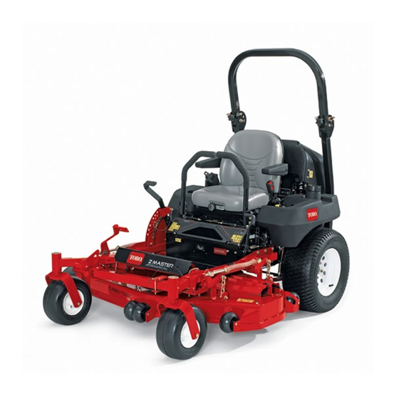
- Page 1 Form No. 3376-555 Rev A Z Master ® Professional 7000 Series Riding Mower With 52in Rear Discharge Mower Model No. 74279TE—Serial No. 313000001 and Up g020465 *3376-555* A Register at www.Toro.com. Original Instructions (EN)
-
Page 2: Table Of Contents
Toro Riding Mower Safety ........5 product properly and safely. Sound Pressure ............5 You may contact Toro directly at www.Toro.com for product Sound Power ............5 and accessory information, help finding a dealer, or to register Vibration Level ............5 your product. -
Page 3: Safety
Safety Fuel System Maintenance ...........35 Servicing the Fuel Filter and Water Seperator ....35 Servicing the Fuel Tank ...........35 This machine meets or exceeds European Standards in Electrical System Maintenance ........36 effect at the time of production. However, improper use Servicing the Battery..........36 or maintenance by the operator or owner can result in Servicing the Fuses ..........37 injury. -
Page 4: Maintenance And Storage
• • Warning–Fuel is highly flammable. Never operate the machine with damaged guards or without safety protective devices in place. – Store fuel in containers specifically designed for this • purpose. Do not change the engine governor settings or overspeed the engine. -
Page 5: Toro Riding Mower Safety
• Follow the manufacturer's recommendations for wheel weights or counterweights to improve stability. The following list contains safety information specific to Toro • Use extreme care with grass catchers or other attachments. products or other safety information that you must know that These can change the stability of the machine and cause is not included in the CEN standard. -
Page 6: Safety And Instructional Decals
Safety and Instructional Decals Safety decals and instructions are easily visible to the operator and are located near any area of potential danger. Replace any decal that is damaged or lost. 98-1977 1. Entanglement hazard, belt—stay away from moving parts. 58-6520 1. - Page 7 107-1866 1. Tipping hazard and sliding or loss of control hazard, drop-offs—do not turn sharply while traveling fast, instead, slow down and turn gradually, do not operate the machine near drop-offs, slopes greater than 15 degrees, or water; keep a safe distance from drop-offs. 2.
- Page 8 107-3968 1. Disengage 3. Parking brake 2. Engage 107-3969 1. Warning—read the Operator's Manual. 107-3961 2. Crushing hazard, mower—engage the parking brake, stop 1. Height of cut in millimeters the engine, and remove the ignition key before working under the mower. 107-7719 1.
- Page 9 108-5957 110-3852 1. Remove the ignition key 2. Continuous tone signals and read the instructions the user that engine is before servicing or overheating. performing maintenance. 110-3853 108-5981 1. Cutting/dismemberment 2. Remove the ignition key hazard, fan and and read the instructions entanglement hazard, before servicing or belt.
- Page 10 116-1716 112-8651 1. Fuel 6. Hour meter 1. Interval 2. Empty 7. PTO 2. Power Take-off (PTO) 3. Half 8. Parking brake 3. Parking brake 4. Full 9. Neutral 4. Neutral 5. Battery 10. Operator presence switch 5. Operator presence switch 6.
- Page 11 Battery Symbols Some or all of these symbols are on your battery 116-1716 1. Explosion hazard 6. Keep bystanders a safe 1. Fuel 6. Hour meter distance from the battery. 2. Empty 7. PTO 2. No fire, open flame, or 7.
- Page 12 107-3963 1. Cutting/dismemberment 2. Cutting/dismemberment 3. Thrown object 4. Before starting the engine, hazard—keep bystanders hazard, mower blade—do hazard of hand or foot, clean grass and debris from not carry passengers and mower blade—remove a safe distance from the the mower belt and pulleys, keep bystanders away.
-
Page 13: Product Overview
110-0820 1. Fast 5. Warning—read the Operator's Manual. 2. Slow 6. Poison and caustic liquid/chemical burn hazard—keep children a safe distance from the battery. 3. Neutral 7. Explosion hazard—no fire, open flames, or smoking; avoid sparks. 4. Reverse 8. To unlock the traction drive, turn the by-pass valve 1 complete revolution counterclockwise using a 5/8 inch or 16 mm wrench. -
Page 14: Fuel Selector Valve
Throttle Control its capabilities. Contact your Authorized Service Dealer or Distributor or go to www.Toro.com for a list of all approved The throttle control is variable between Fast and Slow. attachments and accessories. -
Page 15: Operation
Operation DANGER In certain conditions, fuel is extremely flammable Note: Determine the left and right sides of the machine and highly explosive. A fire or explosion from fuel from the normal operating position. can burn you and others and can damage property. •... -
Page 16: Filling The Fuel Tank
• Monitor seals, hoses, gaskets in contact with fuel as they may be degrade over time. • Fuel filter plugging maybe expected for a time after converting to biodiesel blends. • Contact your distributor if you wish for more information on biodiesel. -
Page 17: Think Safety First
Important: Lower the roll bar only when absolutely necessary. 1. Remove the hairpin cotter pins and remove the two pins (Figure 8). 2. Lower the roll bar to the down position. There are two down positions. See Figure 7 for the positions. 3. -
Page 18: Operating The Parking Brake
2. Pull up and back on the parking brake lever to set the parking brake (Figure 11). The parking brake lever should stay firmly in the engaged position. WARNING Parking brake may not hold machine parked on a slope and could cause personal injury or property damage. -
Page 19: Starting The Engine In Cold Weather
6. Turn the ignition key clockwise to the run position (Figure 13). 7. Push the glow plug switch for 10 seconds. The light will turn on. 8. Release the switch after 10 seconds. The light will turn off. Figure 13 1. -
Page 20: Operating The Power Take Off (Pto)
Note: Do not use fuel left over from the summer. Use only fresh winter grade diesel fuel. Stopping the Engine 1. Disengage the PTO, move the motion control levers to the neutral locked position and set the parking brake (Figure 15 ). 2. -
Page 21: Driving Forward Or Backward
Driving Forward or Backward The throttle control regulates the engine speed as measured in rpm (revolutions per minute). Place the throttle control in the fast position for best performance. Always operate in the full throttle position when mowing. CAUTION Machine can spin very rapidly. Operator may lose control of machine and cause personal injury or Figure 16 damage to machine. -
Page 22: Stopping The Machine
CAUTION Children or bystanders may be injured if they move or attempt to operate the machine while it is unattended. Always remove the ignition key and set the parking brake when leaving the machine unattended, even if just for a few minutes. Adjusting the Height-of-Cut The height-of-cut is adjusted from 1-1/2 to 5 inch (38 to 127 mm) in 1/4 inch (6 mm) increments by relocating... -
Page 23: Adjusting The Anti-Scalp Rollers
Adjusting the Anti-Scalp Rollers Whenever you change the height-of-cut, it is recommended to adjust the height of the anti-scalp rollers. 1. Disengage the PTO, move the motion control levers to the neutral locked position and set the parking brake. 2. Stop the engine, remove the key, and wait for all moving parts to stop before leaving the operating position. -
Page 24: Unlatching The Seat
Important: Do not rotate by-pass valves more than 1 turn. This prevents valves from coming out of the body and causing fluid to run out. 3. Disengage parking brake before pushing. Changing to Machine Operation Rotate the by-pass valves clockwise 1 turn to operate machine (Figure 24). -
Page 25: Loading Machines
instructions. Knowing this information could help you, your WARNING family, pets or bystanders avoid injury. Loading a unit onto a trailer or truck increases the To transport the machine: possibility of backward tip-over and could cause serious injury or death. •... - Page 26 4. Set the foot of stand on the ground and rest the latch WARNING on the pivot tab (Figure 27). The machine could fall onto someone and cause 5. Start the engine and put it at half throttle. serious injury or death. Note: For best results, place the foot of stand into •...
-
Page 27: Operating Tips
File down any nicks and sharpen the it is late fall when grass grows more slowly. blades as necessary. If a blade is damaged or worn, replace it immediately with a genuine TORO replacement blade. Mowing Direction Alternate mowing direction to keep the grass standing straight. -
Page 28: Maintenance
• Adjust the caster pivot bearing Every 500 hours • Adjust the electric clutch. • Change the hydraulic filter and hydraulic oil when using Toro® HYPR-OIL™ 500 hydraulic oil. • Grease the front caster pivots (more often in dirty or dusty conditions). -
Page 29: Lubrication
Important: Refer to your Engine Operator's Manual for additional maintenance procedures. CAUTION If you leave the key in the ignition switch, someone could accidently start the engine and seriously injure you or other bystanders. Remove the key from the ignition and disconnect the wire from the spark plug(s) before you do any maintenance. -
Page 30: Greasing The Mower Deck And Belt Idlers
Greasing the Mower Deck and Belt Idlers Service Interval: Every 25 hours—Grease the mower deck and spindles. Every 25 hours—Grease the pump belt idler arm. Every 25 hours—Grease the drive belt idler arm. Grease with No. 2 general purpose lithium base or molybdenum base grease. -
Page 31: Engine Maintenance
Engine Maintenance Installing the Air Filter 1. If installing a new filter, check the filter for shipping damage. Do not use a damaged filter. Servicing the Air Cleaner 2. Carefully slide the filter into the filter body (Figure 33). Note: Check the filters more frequently if operating Ensure that it is fully seated by pushing on the outer conditions are extremely dusty or sandy. -
Page 32: Servicing The Engine Oil
Servicing the Engine Oil Oil Type: High-quality detergent oil classified API Service CD or higher for diesel engines. Do not use special additives with recommended oils. Crankcase Capacity: 3.9 quarts (3.7 liters) Viscosity: See the table below: Figure 35 Figure 34 1. -
Page 33: Changing The Engine Oil
Changing the Engine Oil Service Interval: After the first 50 hours Every 100 hours 1. Start the engine and let it run for five minutes. This warms the oil so it drains better. 2. Park the machine on a level surface. 3. -
Page 34: Changing The Engine Oil Filter
Every 200 hours 1. Drain the oil from the engine; refer to Changing the Engine Oil. Place a drip pan beneath the oil drip tray to receive oil from the oil filter and oil passages in the engine. 2. Turn the filter counterclockwise to remove it (Figure 41 and Figure 42). -
Page 35: Fuel System Maintenance
Fuel System 2. Disengage the PTO, move the motion control levers to the neutral locked position and set the parking brake. Maintenance 3. Stop the engine, remove the key, and wait for all moving parts to stop before leaving the operating position. Servicing the Fuel Filter and 4. -
Page 36: Electrical System Maintenance
Electrical System 1. Disengage the PTO, move the motion control levers to the neutral locked position and set the parking brake. Maintenance 2. Stop the engine, remove the key, and wait for all moving parts to stop before leaving the operating position. Servicing the Battery 3. -
Page 37: Servicing The Fuses
prevent battery damage when the temperature is below 32°F (0°C). 1. Make sure the filler caps are installed in battery. Charge battery for 10 to 15 minutes at 25 to 30 amps or 30 minutes at 10 amps. 2. When the battery is fully charged, unplug the charger from the electrical outlet, then disconnect the charger leads from the battery posts (Figure 47). -
Page 38: Drive System Maintenance
Drive System Maintenance Adjusting the Tracking The machine has a knob for adjusting the tracking located under the seat. Important: Adjust the handle neutral and hydraulic pump neutral before adjusting the tracking. Refer to Adjusting the Handle Neutral in Controls System Maintenance (page 47) and Adjusting the Hydraulic Pump Neutral in Hydraulic System Maintenance (page 48). -
Page 39: Checking The Tire Pressure
Checking the Wheel Lug Nuts Check and torque the wheel lug nuts to 90-95 ft-lb (122-129 N-m). Checking the Wheel Hub Slotted Nut Service Interval: After the first 100 hours—Check the wheel hub slotted nut. Every 500 hours—Check the wheel hub slotted nut. After the first 100 hours—Check the wheel lug nuts. -
Page 40: Adjusting The Caster Pivot Bearing
Adjusting the Caster Pivot 4. Remove the side or rear plug on the gear box. (Figure 53). Bearing 5. The oil should be up to the opening of the gear box. Service Interval: Every 500 hours (or yearly, which ever 6. - Page 41 10. Tighten the lock nuts until there is slight binding on the feeler gauge but it can be moved easily within the air gap (Figure 56). 11. Repeat this for the remaining slots. 12. Check each slot again and make slight adjustments until the feeler gauge between the rotor and armature has very slight contact between them.
-
Page 42: Cooling System Maintenance
Cooling System 2. Unlatch the seat and tilt the seat up. 3. With the engine cool, check the overflow bottle level. Maintenance The fluid needs to be up to the bump on the outside of the overflow bottle (Figure 57). Servicing the Cooling System 4. -
Page 43: Brake Maintenance
Brake Maintenance Adjusting the Parking Brake Service Interval: Every 25 hours Every 200 hours 1. Engage the parking brake, lever up. 2. Measure the length of the spring. Measurement should be 2-1/2 inch (64 mm) between the washers (Figure 59). 3. -
Page 44: Belt Maintenance
Belt Maintenance 8. Adjust the mower deck to the 3 inch (76mm) height-of-cut position. 9. To increase the belt tension, rotate the ratchet or Inspecting the Belts breaker bar counterclockwise to move the fixed idler arm until there is 6–1/2 inches (16.5 cm) between the Service Interval: Every 100 hours—Inspect the belts for spring hooks (Figure 61). -
Page 45: Replacing The Pto Drive Belt
G012347 Figure 63 g012506 1. Bolt 2. Front engine panel Figure 62 1. Belt cover 3. Bolt 4. Remove the spring from the idler arm (Figure 64). 2. Latch 4. Install tab into the slot 5. Remove the clutch stop bracket. 6. -
Page 46: Replacing The Pump Drive Belt
Replacing the Pump Drive Belt 5. If the deflection is correct, tighten the bottom and upper bolt (Figure 66). Service Interval: Every 50 hours—Check the pump drive belt. Note: Remove the PTO drive belt first if the pump drive belt needs to be replaced. 1. -
Page 47: Controls System Maintenance
Controls System Note: Keeping rearward pressure on the lever will keep the pin at the end of the slot and allow the Maintenance adjustment bolt to move the lever to the appropriate position. 10. Tighten the nut and jam nut (Figure 68). Adjusting the Control Handle 11. -
Page 48: Hydraulic System Maintenance
Every 250 hours—Change the hydraulic filter and 8. Install cap on filler neck. ® hydraulic oil when using Mobil 1 oil. Every 500 hours—Change the hydraulic filter and hydraulic oil when using Toro ® HYPR-OIL ™ hydraulic oil. Use summer filter above 32°F (0°C) Use winter filter below 32°F (0°C) -
Page 49: Bleeding The Hydraulic System
Important: Do not substitute automotive oil filter for leaks. If one or both wheels will not drive, refer to or severe hydraulic system damage may result. Bleeding Hydraulic System. 3. Place drain pan under filter, remove the old filter and 13. -
Page 50: Setting The Hydraulic Pump Neutral Position
Setting the Right-hand Hydraulic Pump WARNING Neutral Position Hydraulic fluid escaping under pressure can 1. Start the engine, open the throttle 1/2 way penetrate skin and cause injury. and release parking brake. Refer to • If hydraulic fluid is injected into the skin it Starting and Stopping the Engine (page 18). - Page 51 Setting the Left-hand Hydraulic Pump WARNING Neutral Position Electrical system will not perform proper 1. Loosen the locknuts at the ball joints on the pump safety shut off with jumper wire installed. control rod (Figure 74). • Remove jumper wire from wire harness 2.
-
Page 52: Mower Deck Maintenance
Mower Deck Maintenance Leveling the Mower at Three Positions Important: There are only three measuring positions needed to level the mower. Setting Up the Machine 1. Position the mower on a flat surface. 2. Disengage the PTO, move the motion control levers to the neutral locked position and set the parking brake. -
Page 53: Servicing The Cutting Blades
If a blade is damaged or worn, replace it immediately with a genuine Toro replacement blade. For 7. Loosen the front swivel jam nuts, at the front of convenient sharpening and replacement, you may want to the right and left swivels, approximately a 1/2 inch keep extra blades on hand. -
Page 54: Inspecting The Blades
Before Inspecting or Servicing the Blades 1. Park the machine on a level surface, disengage the blade control (PTO), and set the parking brake. 2. Turn the ignition key to Off and remove the key. 3. Disconnect the spark plug wire(s) from the spark plug(s). -
Page 55: Removing The Blades
Important: The curved part of the blade must be and continued safety conformance of the machine, use pointing upward toward the inside of the mower to genuine TORO replacement blades. Replacement blades ensure proper cutting. made by other manufacturers may result in non-conformance with safety standards. -
Page 56: Cleaning
Cleaning Storage Cleaning and Storage Cleaning Under the Mower 1. Disengage the power take off (PTO), set the parking Remove the grass buildup under the mower daily. brake, and turn the ignition key to Off. Remove the key. 1. Disengage the PTO, move the motion control levers to 2. - Page 57 C. Stop the engine, allow it to cool, and drain the fuel tank; refer to Servicing the Fuel Tank in Fuel System Maintenance (page 35). D. Restart the engine and run it until it stops. E. Dispose of fuel properly. Recycle as per local codes.
-
Page 58: Troubleshooting
Troubleshooting Problem Possible Cause Corrective Action The starter does not crank. 1. The blade control (PTO) is engaged. 1. Move the blade control (PTO) to the disengaged position. 2. The parking brake is not on. 2. Set the parking brake. 3. - Page 59 Problem Possible Cause Corrective Action The cutting height is uneven. 1. The cutting blade(s) is/are not sharp. 1. Sharpen the blade(s). 2. The cutting blade(s) is/are bent. 2. Install new cutting blade(s). 3. The mower deck is not level. 3. Level the mower deck from side-to-side and front-to-rear.
-
Page 60: Schematics
Schematics g012068 Wire Diagram (Rev. A) - Page 61 Notes:...
- Page 62 Notes:...
- Page 63 The Way Toro Uses Information Toro may use your personal information to process warranty claims, to contact you in the event of a product recall and for any other purpose which we tell you about. Toro may share your information with Toro's affiliates, dealers or other business partners in connection with any of these activities. We will not sell your personal information to any other company.
- Page 64 Instructions for Obtaining Warranty Service The Toro Company and its affiliate, Toro Warranty Company, pursuant to If you think that your Toro Product contains a defect in materials or an agreement between them, jointly promise to the original purchaser workmanship, follow this procedure: to repair the Toro Products listed below if defective in materials or 1.