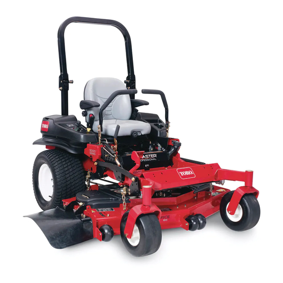
Toro Z Master Professional 7000 Series Operator's Manual
Riding mower with 52in, 60in, or 72in turbo force side discharge mower
Hide thumbs
Also See for Z Master Professional 7000
Series:
- Operator's manual (364 pages) ,
- Setup instructions (16 pages) ,
- Operator's manual (80 pages)
Table of Contents
Advertisement
Quick Links
Register at www.Toro.com.
Original Instructions (EN)
Z Master
®
Series Riding Mower
With 52in, 60in, or 72in TURBO FORCE
Side Discharge Mower
Model No. 74266—Serial No. 401900000 and Up
Model No. 74267—Serial No. 402100000 and Up
Model No. 74274—Serial No. 402090000 and Up
Form No. 3417-819 Rev B
Professional 7000
®
*3417-819* B
Advertisement
Table of Contents

Related Manuals for Toro Z Master Professional 7000 Series


Summary of Contents for Toro Z Master Professional 7000 Series
- Page 1 With 52in, 60in, or 72in TURBO FORCE ® Side Discharge Mower Model No. 74266—Serial No. 401900000 and Up Model No. 74267—Serial No. 402100000 and Up Model No. 74274—Serial No. 402090000 and Up *3417-819* B Register at www.Toro.com. Original Instructions (EN)
- Page 2 For the Operator’s Manual, the complete warranty included with the machine. details, or to register your product, use the QR code or visit www.Toro.com. You may also call us WARNING at 1-888-384-9939 to request a written copy of the product warranty.
-
Page 3: Table Of Contents
Contents Model No. Safety ............... 4 General Safety ........... 4 Serial No. Slope Indicator ........... 5 Safety and Instructional Decals ......6 This manual identifies potential hazards and has Product Overview ........... 14 safety messages identified by the safety-alert symbol Controls ............ -
Page 4: Safety
Safety Servicing the Engine Oil........40 Fuel System Maintenance ........44 Servicing the Fuel Filter and Water This machine has been designed in accordance with Seperator ............44 ANSI B71.4-2012. Servicing the Fuel Tank........45 Electrical System Maintenance ......46 Electrical System Safety ........ -
Page 5: Slope Indicator
Slope Indicator g011841 Figure 3 You may copy this page for personal use. 1. The maximum slope you can operate the machine on is 15 degrees. Use the slope chart to determine the degree of slope of hills before operating. Do not operate this machine on a slope greater than 15 degrees. Fold along the appropriate line to match the recommended slope. -
Page 6: Safety And Instructional Decals
Safety and Instructional Decals Safety decals and instructions are easily visible to the operator and are located near any area of potential danger. Replace any decal that is damaged or missing. decal93-7818 93-7818 decalbatterysymbols 1. Warning—read the Operator's Manual for instructions on Battery Symbols torquing the blade bolt/nut to 115 to 149 N∙m (85 to 110 ft-lb). - Page 7 decal107-2114 107-2114 decal107-1860 107-1860 decal107-3069 107-3069 1. Warning—there is no rollover protection when the roll bar is down. 2. To avoid injury or death from a rollover accident, keep the roll bar in the fully raised and locked position and wear the seat belt.
- Page 8 decal107-3963 107-3963 1. Cutting/dismemberment 2. Cutting/dismemberment 3. Thrown object 4. Before starting the engine, hazard, mower blade—do hazard of hand or foot, hazard—keep bystanders clean grass and debris from a safe distance away from not carry passengers and mower blade—remove the the mower belt and pulleys, keep bystanders away.
- Page 9 decal107-7719 107-7719 1. Cutting/dismemberment hazard, fan and entanglement hazard, belt—stay away from moving parts. 2. Before starting the engine, clean grass and debris from the mower belt and pulleys, insert the key, and start the engine. decal107-3968 107-3968 1. Disengage 3.
- Page 10 decal110-0820 110-0820 1. Fast 5. Warning—read the Operator's Manual. 2. Slow 6. Poison and caustic liquid/chemical burn hazard—keep children a safe distance away from the battery. 3. Neutral 7. Explosion hazard—no fire, open flames, or smoking; avoid sparks. 4. Reverse 8.
- Page 11 decal114-9600 114-9600 1. Read the Operator's Manual. decal117-3848 117-3848 1. Thrown object hazard—keep bystanders a safe distance away from the machine. 2. Thrown object hazard, mower—do not operate the machine without the deflector, discharge cover, or grass collection system in place. 3.
- Page 12 decal127-0326 127-0326 1. Read the Operator's 3. Remove the key and read the Operator's Manual. decal121-7562 121-7562 Manual before performing maintenance or servicing 1. Push to start 4. Variable speed control the machine. 2. Read the Operator’s 5. Fast 2. Height of cut Manual for more information on preheating the engine.
- Page 13 decal132-0871 132-0871 Note: This machine complies with the industry standard stability test in the static lateral and longitudinal tests with the maximum recommended slope indicated on the decal. Review the instructions for operating the machine on slopes in the Operator’s Manual as well as the conditions in which you would operate the machine to determine whether you can operate the machine in those conditions on that day and at that site.
-
Page 14: Product Overview
Controls Product Overview Become familiar with all the controls before you start the engine and operate the machine. Control Panel g208514 Figure 4 g010363 Figure 5 1. Height of cut deck-lift 7. Fuel cap pedal 1. Hour meter 6. Glow-plug light 2. - Page 15 Authorized Service Dealer or authorized Toro Use the N position with the EUTRAL LOCK distributor or go to www.Toro.com for a list of all safety-interlock system to engage and to determine approved attachments and accessories. the N position. EUTRAL...
-
Page 16: Before Operation
Operation containers on the ground, away from your vehicle before filling. • Remove the equipment from the truck or trailer Note: Determine the left and right sides of the and refuel it while it is on the ground. If this is not machine from the normal operating position. - Page 17 Biodiesel Ready This machine can also use a biodiesel blended fuel of up to B20 (20% biodiesel, 80% petrodiesel). The petrodiesel portion should be low or ultra low sulfur. Observe the following precautions: • The biodiesel portion of the fuel meet specification ASTM D6751 or EN14214.
-
Page 18: Performing Daily Maintenance
Using the Rollover-Protection System (ROPS) WARNING To avoid injury or death from rollover, keep the roll bar in the fully raised, locked position and use the seat belt. Ensure that the seat is secured to the machine. WARNING There is no rollover protection when the roll bar is in the down position. -
Page 19: Using The Safety-Interlock System
Using the Safety-Interlock System WARNING If safety-interlock switches are disconnected or damaged, the machine could operate unexpectedly causing personal injury. • Do not tamper with the interlock switches. • Check the operation of the interlock switches daily, and replace any damaged switches before operating the machine. -
Page 20: Positioning The Seat
Unlatching the Seat operate as described below, have an Authorized Service Dealer repair the safety system immediately. Move the seat to the most rearward position. Sitting on the seat, engage the parking brake and move the blade-control switch (PTO) to the Note: This prevents interference when you position. -
Page 21: During Operation
• Use only accessories and attachments approved • Never carry passengers on the machine and keep by Toro. bystanders and pets away from the machine • This machine produces sound levels in excess during operation. - Page 22 injury or death. The operator is responsible for safe slope operation. Operating the machine on any slope requires extra caution. Before using the machine on a slope, do the following: – Review and understand the slope instructions in the manual and on the machine. –...
-
Page 23: Operating The Parking Brake
Operating the Parking Engaging the Blade-Control Switch (PTO) Brake Note: Engaging the blade-control switch (PTO) with Always engage the parking brake when you stop the the throttle position at half or less causes excessive machine or leave it unattended. wear to the drive belts. Engaging the Parking Brake Park the machine on a level surface. -
Page 24: Starting The Engine In Normal Weather
Starting the Engine in Starting the Engine Normal Weather in Cold Weather (Below 23°F or -5°C) Important: Use starting cycles of no more than 30 seconds per minute to avoid overheating the Use the correct engine oil for the starting temperature; starter motor. -
Page 25: Shutting Off The Engine
Shutting Off the Engine Using the Motion-Control Levers CAUTION Children or bystanders may be injured if they move or attempt to operate the machine while it is unattended. Always remove the key and engage the parking brake when leaving the machine unattended. - Page 26 Driving Backward WARNING Move the levers to the center, unlocked position. The machine can spin very rapidly. You may lose control of the machine and cause To go backward, slowly pull the motion-control personal injury or damage to the machine. levers rearward (Figure 27).
-
Page 27: Using The Side Discharge
Using the Side Discharge Adjusting the Height of Cut The mower has a hinged grass deflector that Adjust the height of cut from 38 to 127 mm (1-1/2 to 5 disperses clippings to the side and down toward the inches) in 6 mm (1/4 inch) increments by moving the turf. -
Page 28: Adjusting The Anti-Scalp Rollers
Adjusting the Anti-Scalp Rollers Whenever you change the height-of-cut, adjust the height of the anti-scalp rollers. Park the machine on a level surface, disengage the blade-control switch, and engage the parking brake. Shut off the engine, remove the key, and wait for all moving parts to stop before leaving the operating position. -
Page 29: Positioning The Flow Baffle
g027727 Figure 32 g005833 Figure 34 Positioning the Flow Baffle The following figures are only recommendations Position C for use. Adjustments vary by grass type, moisture content, and the height of the grass. This is the full open position. The suggested use for Note: this position is as follows: If the engine power draws down and the... -
Page 30: Operating With The Overheat Sensor
Cutting more than that is not recommended unless damaged or worn, replace it immediately with a grass is sparse, or it is late fall when grass grows genuine Toro replacement blade. more slowly. Alternating the Mowing Direction Alternate the mowing direction to keep the grass standing straight. -
Page 31: After Operation
Pushing the Machine by After Operation Hand After Operation Safety Important: Always push the machine by hand. Never tow the machine because hydraulic damage may occur. After Operation Safety Pushing the Machine General Safety Park the machine on a level surface, disengage •... -
Page 32: Transporting The Machine
Changing to Machine Operation Transporting the Machine Rotate the bypass valves clockwise 1 turn to operate Use a heavy-duty trailer or truck to transport the machine (Figure 37). machine. Use a full-width ramp. Ensure that the trailer or truck has all the necessary brakes, lighting, and Note: Do not over-tighten the bypass valves. - Page 33 If using a trailer, connect it to the towing vehicle and connect the safety chains. If applicable, connect the trailer brakes and lights. Lower the ramp, ensuring that the angle between the ramp and the ground does not exceed 15 degrees (Figure 38).
-
Page 34: Maintenance
Maintenance Recommended Maintenance Schedule(s) Maintenance Service Maintenance Procedure Interval • Check the engine cooling system level. • Adjust the mower belt tension (for 72-inch mowers only). After the first 8 hours • Check the hydraulic fluid. • Change the hydraulic filter. After the first 25 hours •... -
Page 35: Pre-Maintenance Procedures
• Adjust the caster-pivot bearing. • Adjust the electric clutch. Every 500 hours • Change the hydraulic filter and hydraulic fluid when using Toro® HYPR-OIL™ 500 hydraulic fluid. • Grease the front caster pivots (more often in dirty or dusty conditions). -
Page 36: Lubrication
Lubrication Adding Grease Lubricate the grease fittings as shown on the Check Service Reference Aid decal (Figure 41). Greasing the Machine Grease more frequently when operating conditions are extremely dusty or sandy. Grease Type: No. 2 lithium or molybdenum grease Park the machine on a level surface, disengage the blade-control switch, and engage the parking brake. -
Page 37: Greasing The Mower Deck And Belt Idlers
Greasing the Mower Deck and Belt Idlers Service Interval: Every 25 hours—Grease the mower deck and spindles. Grease with No. 2 lithium or molybdenum grease. Important: Make sure that the cutting-unit spindles are full of grease weekly. Park the machine on a level surface, disengage the blade-control switch, and engage the parking brake. -
Page 38: Lubricating The Caster-Wheel Hubs
Lubricating the Insert the assembled nut and axle into the wheel on the side of the wheel with the new seal and Caster-Wheel Hubs bearing. With the open end of the wheel facing up, fill Service Interval: Yearly the area inside the wheel around the axle full of Park the machine on a level surface, disengage general-purpose grease. -
Page 39: Engine Maintenance
Engine Maintenance Engine Safety • Shut off the engine before checking the oil or adding oil to the crankcase. • Keep your hands, feet, face, clothing, and other body parts away the muffler and other hot surfaces. Servicing the Air Cleaner Note: Check the filters more frequently if operating conditions are extremely dusty or sandy. -
Page 40: Servicing The Engine Oil
g001061 Figure 47 Preparing to Service the Engine Important: The fasteners for the front engine panel are designed to remain on the machine after g001048 cover removal. Loosen all of the fasteners a few Figure 46 turns so that the panel is loose but still attached, 3. - Page 41 Checking the Engine-Oil Level Important: Add the oil very slowly and do not block the opening of the filler hole Service Interval: Before each use or daily (Figure 40). If you add oil too fast or block the hole, the oil could back up and foul the Note: Check the oil when the engine is cold.
- Page 42 Changing the Engine-Oil Filter Service Interval: After the first 50 hours Every 200 hours Drain the oil from the engine; refer to Draining the Engine Oil (page 41). Change the engine-oil filter (Figure 52). g032646 g032649 g032642 Figure 51 Note: Dispose of the used oil at a recycling center.
- Page 43 Changing the Engine Oil Adding Engine Oil Tilt the seat forward and remove the front engine Service Interval: After the first 50 hours panel (Figure 54). Every 100 hours Start the engine and let it run for 5 minutes. Note: This warms the oil so it drains better.
-
Page 44: Fuel System Maintenance
Fuel System Maintenance WARNING Fuel-system components are under high pressure. The use of improper components can result in system failure, fuel leakage, and possible explosion. Use only approved fuel lines and fuel filters. Servicing the Fuel Filter and Water Seperator g001163 Figure 56 Service Interval: Every 40 hours—Drain the water... -
Page 45: Servicing The Fuel Tank
g007169 Figure 58 1. Drain valve 3. Back of machine 2. Water separator Changing the Fuel Filter Never install a dirty fuel filter if it is removed from the fuel line. Allow the machine to cool down. Park the machine on a level surface, disengage g007697 the blade-control switch, and engage the parking Figure 59... -
Page 46: Electrical System Maintenance
Electrical System WARNING Incorrectly removing the cables from battery Maintenance could damage the machine and cables, causing sparks. Sparks can cause the battery gasses to explode, resulting in personal Electrical System Safety injury. • Disconnect the battery before repairing the •... -
Page 47: Servicing The Fuses
Installing the Battery Note: Position the battery in the tray with the terminal posts opposite from the hydraulic tank. g000960 Figure 62 1. Positive battery post 3. Red (+) charger lead 2. Negative battery post 4. Black (-) charger lead Servicing the Fuses The electrical system is protected by fuses. -
Page 48: Drive System Maintenance
Drive System Maintenance Adjusting the Tracking The machine has a knob for adjusting the tracking located under the seat. Important: Adjust the handle neutral and hydraulic pump neutral before adjusting the tracking; refer to Adjusting the Control Handle Neutral Position (page 58) Setting the Hydraulic Pump Neutral Position (page 62). -
Page 49: Checking The Wheel-Hub Slotted Nut
Checking the Wheel-Hub Slotted Nut Service Interval: After the first 100 hours—Check the wheel-hub slotted nut. Every 500 hours—Check the wheel-hub slotted nut. Torque the slottled nut to 286 to 352 N∙m (211 to 260 ft-lb). Note: Do not use anti-seize compound on the wheel hub. -
Page 50: Adjusting The Electric Clutch
Adjusting the Electric Clutch Service Interval: Every 500 hours The clutch is adjustable to ensure proper engagement and proper braking. Park the machine on a level surface, disengage the blade-control switch, and engage the parking brake. Shut off the engine, remove the key, and wait for all moving parts to stop before leaving the operating position. - Page 51 Install the rubber clutch strap to the mower frame with the 2 previously removed bolts and nuts (Figure 69). Pull up on the spring-loaded idler for the PTO-drive belt and install it onto the clutch pulley (Figure 68). Plug in the electric connection for the clutch (Figure 69).
-
Page 52: Cooling System Maintenance
Cooling System Note: Do not open the radiator cap. Doing this may induce air into the cooling system. Maintenance Position the machine on a level surface, shut off the engine, and engage the parking brake. Unlatch the seat and tilt the seat up. Servicing the Cooling With the engine cool, check the overflow bottle System... -
Page 53: Brake Maintenance
Cleaning the Hydraulic-Fluid Brake Maintenance Cooler and Radiator Screen Adjusting the Parking Service Interval: Before each use or daily Brake Before each use, check and clean the radiator screen and oil cooler. Remove any buildup of grass, dirt or other debris from the oil cooler and radiator screen Service Interval: Every 25 hours with compressed air (Figure... -
Page 54: Belt Maintenance
Belt Maintenance Inspecting the Belts Service Interval: Every 100 hours Check the belts for squealing when the belt is rotating, blades slipping when cutting grass, frayed belt edges, burn marks and cracks are signs of a worn mower belt. Replace the mower belt if any of these conditions are evident. -
Page 55: Adjusting The Mower Belt Tension
While holding the belt tension and spring length, tighten the idler plate bolts that secure the idler plate (Figure 77). g006535 Figure 76 g006478 1. Belt cover 3. Insert slot into the tab Figure 77 2. Latch 1. Belt guide (install at a 45 4. -
Page 56: Replacing The Pto-Drive Belt
Replacing the PTO-Drive Belt Service Interval: Every 50 hours—Check the PTO-drive belt. Park the machine on a level surface, disengage the blade-control switch, and engage the parking brake. Shut off the engine, remove the key, and wait for all moving parts to stop before leaving the operating position. -
Page 57: Replacing And Tensioning The Alternator Belt
g007177 Figure 80 1. Clutch 3. Spring g001295 Figure 81 2. Pump drive belt 4. Spring-loaded idler pulley 1. Oil cooler shield 3. Engine straps 2. Bolts Replacing and Tensioning Remove the 4 bolts holding the oil cooler and the Alternator Belt position the oil cooler to the side (Figure 82). -
Page 58: Controls System Maintenance
Controls System Install the oil cooler shield and engine straps to the rear frame with the 4 bolts previously Maintenance removed (Figure 81). Install the engine straps to the side of the machine (Figure 81). Adjusting the Control Tighten the bottom bolt and install the upper bolt Handle Neutral Position holding the alternator and cover (Figure... -
Page 59: Hydraulic System Maintenance
Use cardboard or paper to find hydraulic leaks. • Safely relieve all pressure in the hydraulic system before performing any work on the hydraulic system. Servicing the Hydraulic System Hydraulic-Fluid Specifications Hydraulic-Fluid Type: Toro ® HYPR-OIL ™ hydraulic fluid or Mobil ® 1 15W-50 fluid g001155 Important: Use the specified fluid. - Page 60 1 fluid. Note: Check the fluid level while the fluid is Every 500 hours—Change the hydraulic warm. The fluid should be between cold and hot. filter and hydraulic fluid when using Toro ® ™ HYPR-OIL 500 hydraulic fluid. If required, add fluid to the hydraulic tank.
- Page 61 g001313 g001043 Figure 88 Figure 89 1. Right hydraulic line 3. Hydraulic tank 1. Hydraulic filter 3. Adapter 2. Hydraulic filter 2. Gasket Apply a thin coat to the rubber gasket on the replacement filter (Figure 89). Bleeding the Hydraulic System Install the replacement hydraulic filter onto the The traction system is self-bleeding;...
-
Page 62: Setting The Hydraulic Pump Neutral Position
Setting the Hydraulic Pump Note: The wheel must stop turning or slightly creep in reverse. Neutral Position Open the throttle to FAST Note: Adjust the handle neutral first. That needs Note: Make sure that the wheel remains to be correct before you can make the following stopped or slightly creeps in reverse;... - Page 63 Setting the Left Hydraulic Pump WARNING Neutral Position The electrical system does not perform proper safety shut off with the jumper Loosen the locknuts at the ball joints on the wire installed. pump control rod (Figure 91). • Remove the jumper wire from the Start the engine, open the throttle 1/2 way and disengage parking brake;...
-
Page 64: Mower Deck Maintenance
Mower Deck Leveling the Mower Side-to-Side Position the right blade side-to-side (Figure 92). Maintenance Leveling the Mower at 3 Positions Important: There are only 3 measuring positions needed to level the mower. Setting Up the Machine Park the machine on a level surface, disengage the blade-control switch, and engage the parking brake. - Page 65 g001040 g001041 Figure 93 Figure 94 1. Rear chain 5. Adjustment bolt 1. Measure here from blade 2. Measure at A and B 2. Rear-support arm 6. Front swivel to hard surface 3. Bolt 7. Front-support arm 4. Jam nut Measure the right blade at the A location, from a level surface to the cutting edge of the blade (Figure...
-
Page 66: Servicing The Cutting Blades
File down any nicks and sharpen the blades as necessary. If a blade is damaged or worn, replace it immediately with a genuine Toro replacement blade. For convenient sharpening and replacement, keep extra blades on hand. - Page 67 Shut off the engine, remove the key, and wait ensure optimum performance and continued safety for all moving parts to stop before leaving the conformance of the machine, use genuine Toro operating position. replacement blades. Replacement blades made by Rotate the blades until the ends face forward other manufacturers may result in nonconformance and backward.
- Page 68 Sharpening the Blades Installing the Blades Use a file to sharpen the cutting edge at both Install the blade onto the spindle shaft (Figure ends of the blade (Figure 99). 101). Note: Important: Maintain the original angle. The curved part of the blade must be pointing upward toward the inside Note: The blade retains its balance if the same...
-
Page 69: Replacing The Grass Deflector
Replacing the Grass Deflector WARNING An uncovered discharge opening could allow the machine to throw objects toward you or bystanders, resulting in serious injury. Also, contact with the blade could occur. • Never operate the machine unless you install a cover plate, a mulch plate, or a grass chute and catcher. -
Page 70: Cleaning
Cleaning Storage Storage Safety Cleaning under the Mower • Shut off the engine, remove the key, wait for all Deck moving parts to stop, and allow the machine to cool before storing it. Service Interval: Before each use or daily •... - Page 71 Run the engine to distribute conditioned fuel through the fuel system for 5 minutes. Shut off the engine, allow it to cool, and drain the fuel tank; refer to Servicing the Fuel Tank (page 45). Note: Start the engine and run it until it shuts off.
-
Page 72: Troubleshooting
Troubleshooting Problem Possible Cause Corrective Action The starter does not crank. 1. The blade-control switch (PTO) is 1. Move the blade-control switch (PTO) engaged. to disengaged. 2. The parking brake is not engaged. 2. Engage the parking brake. 3. The drive levers are not in the 3. - Page 73 Problem Possible Cause Corrective Action There is abnormal vibration. 1. The cutting blade(s) is/are bent or 1. Install new cutting blade(s). unbalanced. 2. The blade mounting bolt is loose. 2. Tighten the blade mounting bolt. 3. The engine mounting bolts are loose. 3.
-
Page 74: Schematics
Schematics g260151 119-0353 (Rev. B) - Page 75 Notes:...