Lennox G71MPP SERIES Unit Information
Hide thumbs
Also See for G71MPP SERIES:
- Installation instructions manual (72 pages) ,
- User's information manual (6 pages)
Table of Contents
Advertisement
Service Literature
G71MPP series units are high−efficiency multi−position
(upflow, downflow, horizontal right and left) gas furnaces
equipped with variable capacity gas valve, variable speed
combustion air inducer and variable speed indoor blower
motor. All models are designed only for direct vent (dual
pipe) venting system. G71MPP units are available in heat-
ing capacities from 66,000 to 132,000 Btuh (19.3 to 38.6
kW) and cooling applications from 2 to 5 tons (7.0 kW to
17.5 kW). Refer to Engineering Handbook for proper siz-
ing.
Units are factory equipped for use with natural gas. Kits are
available for conversion to LPG operation. G71MPP model
units are equipped with the Lennox SureLight
pacity integrated control. All G71MPP units meet the Califor-
nia Nitrogen Oxides (NO
) Standards and California Sea-
x
sonal Efficiency requirements.
All specifications in this manual are subject to change. Pro-
cedures outlined in this manual are presented as a recom-
mendation only and do not supersede or replace local or
state codes. In the absence of local or state codes, the
guidelines and procedures outlined in this manual (except
where noted) are recommendations only and do not consti-
tute code.
TABLE OF CONTENTS
. . . . . . . . . . . . . . . . . . . . . . . . . . . . .
. . . . . . . . . . . . . . . . . . . . . .
. . . . . . . . . . . . . . . . . . . . . . . . . . . . . .
. . . . . . . . . . . . . . . . . . . . . . .
. . . . . . . . . . . . . . . . . . . . . . . . . . . . . . . . .
. . . . . . . . . . . . . . . . . . . . . . . . .
. . . . . . . . . . . . . . . . . . . . . . . . .
II Installation
. . . . . . . . . . . . . . . . . . . . . . . . . . . .
III Start Up
. . . . . . . . . . . . . . . . . . . . . . . . . . . . . . .
IV Heating System Service Checks
V Typical Operating Characteristics
VI Maintenance
. . . . . . . . . . . . . . . . . . . . . . . . . .
VII Wiring and Sequence of Operation
VIII Field Wiring
. . . . . . . . . . . . . . . . . . . . . . . . .
Corp. 0804−L2
Revised 05−05−2008
G71MPP SERIES UNITS
®
variable ca-
Page 2
Page 3
Page 4
Page 16
16
28
30
Page 36
Page 47
. . . . . . . . .
Page 48
. . . . . . . . .
Page 51
Page 52
. . . . . .
Page 54
Page 61
Page 1
WARNING
Improper installation, adjustment, alteration, service
or maintenance can cause property damage, person-
al injury or loss of life. Installation and service must
be performed by a licensed professional installer (or
equivalent), service agency or the gas supplier.
WARNING
Electric shock hazard. Can cause injury
or death. Before attempting to perform
any service or maintenance, turn the
electrical power to unit OFF at discon-
nect switch(es). Unit may have multiple
power supplies.
WARNING
Sharp edges.
Be careful when servicing unit to avoid sharp edges
which may result in personal injury.
G71MPP
© 2008 Lennox Industries Inc.
Advertisement
Table of Contents
Troubleshooting

Related Manuals for Lennox G71MPP SERIES


Summary of Contents for Lennox G71MPP SERIES
- Page 1 Corp. 0804−L2 Service Literature Revised 05−05−2008 G71MPP SERIES UNITS G71MPP series units are high−efficiency multi−position (upflow, downflow, horizontal right and left) gas furnaces equipped with variable capacity gas valve, variable speed combustion air inducer and variable speed indoor blower motor. All models are designed only for direct vent (dual pipe) venting system.
- Page 2 SPECIFICATIONS Model No. G71MPP G71MPP G71MPP G71MPP G71MPP Heating −36B−070 −36C−090 −60C−090 −60C−110 −60D−135 Performance Maximum Input − Btuh 66,000 88,000 88,000 110,000 132,000 Output − Btuh 60,000 81,000 81,000 103,000 123,000 Temperature rise range − _F 50 − 80 60 −...
- Page 3 OPTIONAL ACCESSORIES B" Width Models C" Width Models D" Width Models FILTER KITS Air Filter and Horizontal (end) Size of filter − in. 87L96 − 18 x 25 x 1 87L97 − 20 x 25 x 1 87L98 − 25 x 25 x 1 Rack Kit Side Return Single...
- Page 4 The effect of static pressure is included in air volumes shown. Lennox Harmony IIIt Zone Control Applications − Minimum blower speed is 250 cfm. The following control board configurations are available. See Installation Instructions for details and DIP switch settings.
- Page 5 The effect of static pressure is included in air volumes shown. Lennox Harmony IIIt Zone Control Applications − Minimum blower speed is 250 cfm. The following control board configurations are available. See Installation Instructions for details and DIP switch settings.
- Page 6 The effect of static pressure is included in air volumes shown. Lennox Harmony IIIt Zone Control Applications − Minimum blower speed is 450 cfm. The following control board configurations are available. See Installation Instructions for details and DIP switch settings.
- Page 7 The effect of static pressure is included in air volumes shown. Lennox Harmony IIIt Zone Control Applications − Minimum blower speed is 450 cfm. The following control board configurations are available. See Installation Instructions for details and DIP switch settings.
- Page 8 The effect of static pressure is included in air volumes shown. Lennox Harmony IIIt Zone Control Applications − Minimum blower speed is 450 cfm. The following control board configurations are available. See Installation Instructions for details and DIP switch settings.
- Page 9 The effect of static pressure is included in air volumes shown. Lennox Harmony IIIt Zone Control Applications − Minimum blower speed is 450 cfm. The following control board configurations are available. See Installation Instructions for details and DIP switch settings.
- Page 10 The effect of static pressure is included in air volumes shown. Lennox Harmony IIIt Zone Control Applications − Minimum blower speed is 450 cfm. The following control board configurations are available. See Installation Instructions for details and DIP switch settings.
- Page 11 The effect of static pressure is included in air volumes shown. Lennox Harmony IIIt Zone Control Applications − Minimum blower speed is 450 cfm. The following control board configurations are available. See Installation Instructions for details and DIP switch settings.
- Page 12 The effect of static pressure is included in air volumes shown. Lennox Harmony IIIt Zone Control Applications − Minimum blower speed is 450 cfm. The following control board configurations are available. See Installation Instructions for details and DIP switch settings.
- Page 13 The effect of static pressure is included in air volumes shown. Lennox Harmony IIIt Zone Control Applications − Minimum blower speed is 450 cfm. The following control board configurations are available. See Installation Instructions for details and DIP switch settings.
- Page 14 The effect of static pressure is included in air volumes shown. Lennox Harmony IIIt Zone Control Applications − Minimum blower speed is 450 cfm. The following control board configurations are available. See Installation Instructions for details and DIP switch settings.
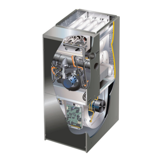
- Page 15 G71MPP PARTS ARRANGEMENT BAG ASSEMBLIES (shipping location) HEAT EXCHANGER BURNER BOX ASSEMBLY WARM HEADER VARIABLE CAPACITY (COLLECTOR BOX) GAS VALVE CONDENSER COIL PRESSURE SWITCH COMBUSTION AIR ASSEMBLY WITH PRESSURE PRESSURE SWITCHES CONDITIONING DEVICE COLD HEADER VARIABLE SPEED (COLLECTOR BOX) COMBUSTION AIR INDUCER SHIPPING BLOCK BURNER ACCESS PANEL (−135 units only)
- Page 16 4. Integrated Control Board(A92) blower deck, before performing any service pro- ® cedure. G71MPP units are equipped with the Lennox SureLight variable capacity integrated control. The system consists A−Control Box of an ignition / blower control (figures 4 and 5) with control 1.
- Page 17 Electronic Ignition justed accordingly to provide the appropriate airflow at any ® At the beginning of the heat cycle the SureLight integrated rate. On the initial call for low fire, the furnace will operate at control monitors the low fire combustion air inducer pres- 40% and will remain there until the heat call is satisfied or a sure switch.
- Page 18 FACTORY TEST HEADER PINS. FACTORY USE ONLY. THERMOSTAT CONNECTIONS (TB1) 1/4" QUICK CONNECT TERMINALS NEUTRALS= 120 VAC NEUTRAL H= 24V HUMIDIFIER OUTPUT L= LENNOX SYSTEM OPERATION MONITOR FIGURE 4 TABLE 12 TABLE 13 ® SureLight Board 6 Pin Terminal Designation...
- Page 19 G71MPP INTEGRATED CONTROL CONFIGURATION GUIDE FIGURE 5 Page 19...
- Page 20 TABLE 14 Thermostat Selection Switch Settings Operation Thermostat Switch 1 Switch 2 Switch 3 Variable Capacity Heat Two−Stage (40% to 100%) Three−Stage Heat Single−Stage 2nd stage delay (40%, 70%, 100%) OFF = 7 minutes ON = 12 minutes 3rd stage delay 10 minutes fixed Two−Stage Heat (W1 70%, W2 100%) Two−Stage...
- Page 21 Switches 10 and 11 −− Cooling Mode Blower Speed Ad- Ramping Option A (Factory Selection) D Motor runs at 50% for 30 seconds. justment −− Switches 10 and 11 are used to select blower D Motor then runs at 82% for approximately 7−1/2 min- speed adjustment settings.
- Page 22 TABLE 20 TABLE 21 Low Heat Blower Speeds High Heat Blower Speeds Blower Blower DIP SWITCH SETTINGS DIP SWITCH SETTINGS Thermostat Speed Thermostat Speed Demand Adjust- Demand Adjust- ments ments +15% +15% +7.5% +7.5% High Heat Low Heat (R to Normal Normal (R to W1)
- Page 23 On−Board Link W914 −− Figure 4 Error Code Recall Mode Select "E" from the menu to access the most recent 10 error On−board link W914, is a clippable connection between ter- codes. Select c" from the Error Code Recall menu to clear minals DS and R on the integrated control.
- Page 24 TABLE 22 Idle Menu Options These options are displayed on the menu when the button is pressed during normal operation DISPLAY ACTION (when button released) No change (idle) remain in idle mode Solid E" enter diagnostic mode Solid −" enter field test mode NOTE −...
- Page 25 TABLE 25 LED 7 Segment Status / Error Code Press the diagnostic push button and hold it to cycle through a menu of options. Every five seconds a new menu item will be displayed. Release the button when the desired mode is displayed. When the solid E"...
- Page 26 TABLE 26 OPERATING SEQUENCE G71MPP, ComfortSenset 7000 Thermostat and Single−Stage Outdoor Unit OPERATING SYSTEM DEMAND SYSTEM RESPONSE SEQUENCE Blower Thermostat Demand Relative Humidity System Step Compressor Comments Condition Status (COOL) NO CALL FOR DEHUMIDIFICATION Compressor and indoor Normal Operation Acceptable High 100% blower follow thermostat...
- Page 27 TABLE 27 OPERATING SEQUENCE G71MPP, ComfortSenset 7000 Thermostat and Two−Stage Outdoor Unit OPERATING SYSTEM DEMAND SYSTEM RESPONSE SEQUENCE Thermostat Demand Relative Humidity Blower System Comments Step Compressor Condition Status (COOL) NO CALL FOR DEHUMIDIFICATION Normal Operation − Acceptable Compressor and indoor blower follow thermostat Normal Operation −...
- Page 28 B−Blower Compartment Figure 7 IMPORTANT Earlier ECM motors used on other Lennox furnace models are not interchangeable with motors used on SECONDARY the G71MPP furnace line. LIMITS (2) A solid-state controller is permanently attached to the motor. The controller is primarily an A.C. to D.C. con- verter.
- Page 29 Motor Start-Up BLOWER B3 HARNESS CONNECTORS When B3 begins start-up, the motor gently vibrates back and forth for a moment. This is normal. During this time the elec- P48 5 Pin tronic controller is determining the exact position of the rotor. Once the motor begins turning, the controller slowly eases SHAFT the motor up to speed (this is called soft-start").
- Page 30 Troubleshooting To verify motor operation see steps below: 1− Remove J48 (5 pin power plug) from P48 on the mo- BLOWER B3 HARNESS CONNECTORS tor. P48 5 Pin 2− With the power on at the furnace and door switch de- P49 4 Pin pressed, use a test meter to verify 120V between pins SHAFT...
- Page 31 C−Heating Components Harmony IIIt 1. Ignitor When the G71MPP is installed in Harmony III applications, The ignitor is made of durable silicon nitride. Ignitor longev- the Harmony III signal is connected to the DS terminals on ity is enhanced by controlling voltage to the ignitor. The the integrated control (figure 4).
- Page 32 Ignitor Location MEASUREMENT IS TO I.D. OF RETENTION RING " 7/32’ 21/64" BURNERS TOP VIEW BRACKET IGNITOR BURNERS FRONT VIEW FIGURE 12 3. Duralock Heat Exchanger 5. Primary Limit Control (S10) Figure 13 shows the primary limit (S10) used on G71MPP G71MPP units use an aluminized steel primary and units located in the heating vestibule panel.
- Page 33 Inlet and outlet pressure taps are located on the valve. event vent outlet or combustion air intake blockage. Both LPG change over kits are available from Lennox. Kits include switches provide this function. burner orifices and an LP gas valve.
- Page 34 Vent Calibration After calibration, the integrated control stores the RPM1 and RPM2 values. The low fire (40%) and high fire (100%) The vent calibration sequence establishes furnace operat- RPM points are calculated by adding margin values to the ing parameters in a specific installation. The integrated RPM1 and RPM2 values.
- Page 35 Duel Pressure Switch 1 − Remove thermostat demand and allow unit to cycle off. 2 − Install a tee in the negative (−) line and a tee in the positive (+) line running from the lower pressure switch to the cold end header box.
- Page 36 II−PLACEMENT AND INSTALLATION TABLE 34 OUTDOOR TERMINATION KITS AND CORRESPONDING EQUIVALENCIES Vent Pipe Length Equivalency (feet) Outdoor Ex- Outdoor Ex- haust Accel- haust Accel- 1−1/2" 2" 3" VENT 2" Wall Plate 3" Wall Plate 2" Wall erator erator Concentric Concentric Concentric PIPE UNIT...
- Page 37 Contact Lennox’ Application Department for assis- both intake and exhaust. tance in sizing vent pipe in these applications.
- Page 38 NOTE − The flue collar on all models is sized to accommo- TABLE 36 MAXIMUM VENT PIPE LENGTHS date 2" Schedule 40 flue pipe. When vent pipe which is larger than 2" must be used in an upflow application, a 2" MAXIMUM EQUIVALENT VENT LENGTH FEET elbow must be applied at the flue collar in order to proper-...
- Page 39 7 − Immediately after applying last coat of cement to pipe, Exhaust Piping (Figures 19 and 20) and while both inside socket surface and end of pipe NOTE − A 2" diameter street ell is located on the blower are wet with cement, forcefully insert end of pipe into deck of 60C−110 units.
- Page 40 TYPICAL EXHAUST PIPE CONNECTIONS AND CONDENSATE TRAP INSTALLATION IN UPFLOW OR DOWNFLOW DIRECT VENT APPLICATIONS (Right−Hand Exit in Upflow Application Shown) 45° 45° 2−1/2", 3", OR 4" 2" PLUG PLUG TRANSITION 2" 2" G71MPP−070, 2" or −090 with 2" SIDE VIEW VENT PLUG 2−1/2", 3", or 4"...
- Page 41 TYPICAL AIR INTAKE PIPE CONNECTIONS UPFLOW OR DOWNFLOW DIRECT VENT APPLICATIONS 2−1/2", (Right−Hand Exit in Upflow Application Shown) 3" OR 2−1/2", TRANSITION 3" OR TRANSITION 2"* PLUG (Must be glued in place) −36B−070 −36B−070 −36B−070 −36C−090 −36C−090 −36C−090 −60C−090 −60C−090 −60C−090 −60C−110 −60C−110...
- Page 42 VENT TERMINATION CLEARANCES FOR INSTALLATIONS IN THE USA AND CANADA* − G71MPP VENT TERMINATION − AIR INLET OF OTHER APPLIANCE less than 10 ft (3.048M) A − Clearance above grade − 12 in. (305mm) minimum. E − Clearance to non−mechanical air supply inlet or outlet for vent installations in USA −...
- Page 43 Details of Intake and Exhaust Piping Terminations for 9. Based on the recommendation of the manufacturer, a Direct Vent Installations multiple furnace installation may use a group of up to four termination kits assembled together horizontally, NOTE − In Direct Vent installations, combustion air is taken from outdoors and flue gases are discharged to outdoors.
- Page 44 EXHAUST VENT EXHAUST 12" (305) ABOVE TERMINATION AVERAGE SNOW ACCUMULATION INTAKE Inches (mm) Front View VENT INTAKE WITH OPTIONAL TERMINATION ELBOW 1/2" (13) Foam Insulation Side View in Unconditioned Space FIELD−PROVIDED FIELD− REDUCER MAY BE REQUIRED PROVIDED EXHAUST VENT TO ADAPT LARGER VENT REDUCER MAY PIPE SIZE TO TERMINATION BE REQUIRED...
- Page 45 12" (305) MAX. for 2" (51) 20" (508) MAX. for 3" (76) Inches (mm) COVER EXHAUST (unless supported) 12" VENT WITH (305) 1/2" (13) EXHAUST FOAM INTAKE INSULATION INTAKE 8" (203) Minimum EXHAUST 12" (305) Minimum 12" MIN. 5" ABOVE GRADE (127) (305) Above Grade...
- Page 46 Heating cable kit is available from Lennox in various 2 − Install condensate trap onto the condensate collar. lengths; 6 ft. (1.8m) − kit no. 26K68; 24 ft. (7.3m) − kit no.
- Page 47 III−START-UP BEFORE BEFORE PLACING THE UNIT INTO OPERA- TION, the unit, smell all around the furnace area for gas. A−Preliminary and Seasonal Checks Be sure to smell next to the floor because some gas is 1 − Inspect electrical wiring, both field and factory installed heavier than air and will settle on the floor.
- Page 48 Refer to the Gas Leak Detector is strongly recommended. It is available G71MPP Installation Instruction. through Lennox under part number 31B2001. See Corp. B−Gas Piping 8411−L10, for further details. Do not use matches, candles, flame or any other source of CAUTION ignition to check for gas leaks.
- Page 49 Use pressure test Revolution 1/2 cu ft Dial 1 cu ft Dial adapter kit (available as Lennox part 10L34) to assist in measurement. 1 − Connect test gauge +" connection to manifold pres sure tap on the gas vavle.
- Page 50 H− High Altitude NOTE − The values given in table are measurements only. NOTE − In Canada, certification for installations at eleva- The gas valve should not be adjusted. tions over 4500 feet (1372 m) is the jurisdiction of local au- The combustion air pressure switch is factory−set and re- thorities.
- Page 51 V−TYPICAL OPERATING CHARACTERISTICS 3 − After plenum thermometers have reached their high- est and steadiest readings, subtract the two readings. A−Blower Operation and Adjustment The difference should be in the range listed on the unit 1 − Blower operation is dependent on thermostat control rating plate.
- Page 52 VI−MAINTENANCE 3 − Remove the drain plug from the condensate trap and empty water. Inspect the trap then reinstall the drain plug and refill trap with water. WARNING Cleaning Heat Exchanger If cleaning the heat exchanger becomes necessary, follow ELECTRICAL SHOCK, FIRE, the below procedures and refer to figure 1 when disassem- OR EXPLOSION HAZARD.
- Page 53 18 − Remove two screws from the front cabinet flange at 37 − Reconnect sensor wire and reconnect 2−pin plug from the blower deck. Spread cabinet sides slightly to allow ignitor. clearance for removal of heat exchanger. 38 − Secure burner box assembly to vestibule panel using 19 −...
- Page 54 VII− Wiring and Sequence of Operation NOTE − The thermostat selection DIP switch on the control 2. Once the control receives a signal that the low−fire board is factory−set in the TWO−STAGE" position. pressure switch has closed, the combustion air induc- er begins a 15−second pre−purge in ignition speed.
- Page 55 ate target rate. If the furnace is operating in the initial 6 − If the heating demand continues beyond the third− heating cycle after power−up, the initial firing rate will stage on delay, the integrated control energizes the in- be approximately 40 percent. The firing rate on subse- ducer at high speed.
- Page 56 A − Sequence of Operation and Troubleshooting Flow Chart IGNITION AND CALL FOR LOW FIRE WITH TWO−STAGE THERMOSTAT Safety Check Verify There Is No Main Burner Flame After Indoor blower OFF Heat OFF Delay (Low Heat Speed) Limit Combustion Air Limit De−Energize Error Code...
- Page 57 CALL FOR HIGH FIRE WITH TWO−STAGE THERMOSTAT 2 Stage Thermostat 1st Call for High Fire? 2nd Stage Recognition Delay (30 Seconds) Combustion Air Inducer ON (100% Rate Speed) High Pressure Switch Increase Combustion Error Code Wait 5 Closes Within Air Inducer Speed Flashes Minutes 10 Seconds?
- Page 58 CALL FOR HEAT SATISFIED RUN MODE (2 STAGE THEREMOSTAT) RUN MODE (SINGLE STAGE THERMOSTAT) 1ST OR 2ND STAGE CALL FOR HEAT ALL ALL INPUTS MONITORED (LIMIT, PRESSURE, INPUTS MONITORED (LIMIT, PRESSURE, CALL FOR HEAT / COOL, FLAME LEVEL) CALL FOR HEAT / COOL, FLAME LEVEL) 2nd Stage Heat 2nd Stage Call for Heat...
- Page 59 IGNITION AND CALL FOR LOW FIRE WITH SINGLE−STAGE THERMOSTAT Safety Check Verify There Is No Main Burner Flame Indoor Blower OFF After Heat OFF Delay (Low Heat Speed) Indoor Blower Limit Limit De−Energize Error Code Combustion Air Switch Closes Within 3 Gas Valve Flashes Inducer ON...
- Page 60 CALL FOR COOLING 1st Stage Cooling Request Received Energize 1st Stage Cooling Contactor (Compressor & Fan) Indoor Blower On After 2−second delay Energize Indoor Blower (Per Ramping Profile) 1st Stage 2nd Stage Cooling Request Cooling Still Active? Request? Energize 2nd Stage Energize Indoor Blower Cooling Contactor (High Cooling mode)
- Page 61 CONTINUOUS LOW SPEED INDOOR BLOWER SEQUENCE OF OPERATION Call for Continuous Blower Indoor Blower On (Speed Determined by Dip Switch settings) Request Maintain Indoor for Cooling Go to Call for Cooling Blower at set speed Received? Go to Call for Heat − 2 Stage Thermostat Request Maintain Indoor for Heat...
- Page 62 VIII− Field Wiring TABLE 44 Field Wiring Applications DIP Switch Settings and On−Board Links (figure 4) W914 W915 (DS to R) (Y1 to Y2) W951 Dehumidifi- Thermostat Wiring Connections DIP Switch 1 Two−Stage (O to R) cation or Cooling Heat Pumps Harmony IIIt 1Heat / 1 Cool...
- Page 63 TABLE 44 Field Wiring Applications DIP Switch Settings and On−Board Links (figure 4) W914 W915 (DS to R) (Y1 to Y2) W951 Dehumidifi- Thermostat Wiring Connections DIP Switch 1 Two−Stage (O to R) cation or Cooling Heat Pumps Harmony IIIt 2 Heat / 2 Cool Intact Intact...
- Page 64 TABLE 44 Field Wiring Applications (Continued) DIP Switch Settings and On−Board Link (figure 4) W914 W915 (DS to R) W951 (Y1 to Y2) Dehumidifi- Wiring Connections Thermostat DIP Switch (O to R) Two−Stage cation or Heat Pumps Cooling Harmony IIIt Dual Fuel DIP Switch 1 Intact...