Lennox G43UF SERIES Unit Information
Hide thumbs
Also See for G43UF SERIES:
- Installation instructions manual (51 pages) ,
- User's information manual (51 pages) ,
- User manual (17 pages)
Table of Contents
Advertisement
Service Literature
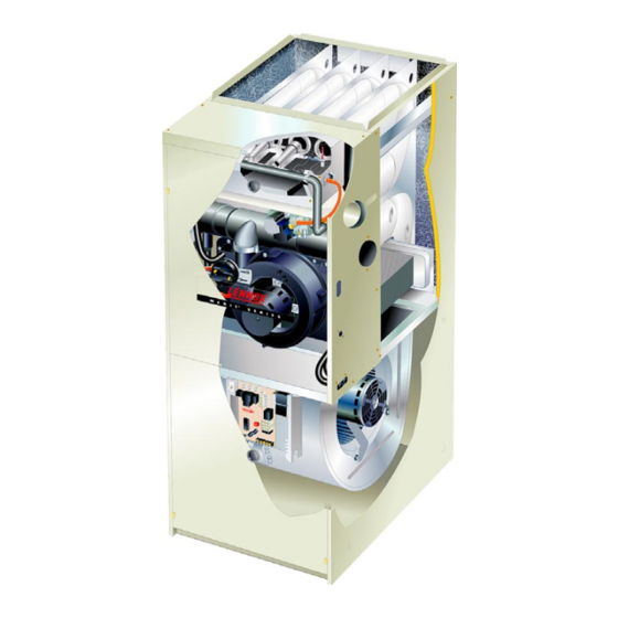
G43UF series units are high−efficiency gas furnaces
manufactured with Lennox DuralokPlust aluminized
steel clamshell−type heat exchangers, with a stainless steel
condensing coil. G43UF units are available in heating in-
put capacities of 44,000 to 132,000 Btuh (13 to 38.6 kW) and
cooling applications from 2 through 5 tons (7.0 through 17.6
kW). Refer to Engineering Handbook for proper sizing.
Units are factory equipped for use with natural gas. A kit is
available for conversion to LPG operation. All G43UF
units are equipped with a hot surface ignition system. The
Gas Valve is redundant to assure safety shut−off as re-
quired by C.S.A.
The heat exchanger, burners and manifold assembly can be
removed for inspection and service. The maintenance section
gives a detailed description on how this is done.
Information contained in this manual is intended for use by
qualified service technicians only. All specifications are sub-
ject to change. Procedures outlined in this manual are pre-
sented as a recommendation only and do not supersede or
replace local or state codes.
WARNING
Electric shock hazard. Can cause injury
or death. Before attempting to perform
any service or maintenance, turn the
electrical power to unit OFF at discon-
nect switch(es). Unit may have multiple
power supplies.
Table of Contents
General
. . . . . . . . . . . . . . . . . . . . . . . . . . . . . . . . . . . . . .
. . . . . . . . . . . . . . . . . . . . . . . . . . . . . . . . .
Blower Performance Data
I−Unit Components
. . . . . . . . . . . . . . . . . . . . . . . . . . . .
II Placement and Installation
III−Start−Up
. . . . . . . . . . . . . . . . . . . . . . . . . . . . . . . . . . .
IV−Heating System Service Checks
V−Typical Operating Conditions
. . . . . . . . . . . . . . . . . . . . . . . . . . . . . . . . . .
VI−Maintenance
. . . . . . . . . . . . . . . . . . . . . . . . . . . . . . .
VII−Wiring and Sequence of Operation
VIII−Troubleshooting
. . . . . . . . . . . . . . . . . . . . . . . . . . .
Revised 2−2006
G43UF SERIES UNITS
. . . . . . . . . . . . . . . . . . . . . .
. . . . . . . . . . . . . . . . . . . .
. . . . . . . . . . . . . .
. . . . . . . . . . . . . . . . .
. . . . . . . . . . .
Corp. 0416−L4
1
2
Improper installation, adjustment, alteration, service
4
or maintenance can cause property damage, person-
9
al injury or loss of life. Installation and service must
18
be performed by a qualified installer, service agency
or the gas supplier.
31
32
35
35
37
Sharp edges.
39
Be careful when servicing unit to avoid sharp edges
which may result in personal injury.
49
Page 1
G43UF
IMPORTANT
WARNING
© 2004 Lennox Industries Inc.
Litho U.S.A.
Advertisement
Table of Contents

Related Manuals for Lennox G43UF SERIES


Summary of Contents for Lennox G43UF SERIES
- Page 1 Corp. 0416−L4 Service Literature Revised 2−2006 G43UF SERIES UNITS G43UF series units are high−efficiency gas furnaces manufactured with Lennox DuralokPlust aluminized steel clamshell−type heat exchangers, with a stainless steel condensing coil. G43UF units are available in heating in- put capacities of 44,000 to 132,000 Btuh (13 to 38.6 kW) and cooling applications from 2 through 5 tons (7.0 through 17.6...
- Page 2 SPECIFICATIONS Model No. G43UF G43UF G43UF G43UF G43UF −24B−045 −24B−070 −36B−070 −36C−090 −36C−090H Heating Canada Only Performance Performance Input − Btuh (kW) 44,000 (12.9) 66,000 (19.3) 66,000 (19.3) 88,000 (25.8) 88,000 (25.8) Output − Btuh (kW) 41,000 (12.0) 60,700 (17.8) 62,000 (18.2) 82,000 (24.0) 81,000 (23.7)
- Page 3 OPTIONAL ACCESSORIES − MUST BE ORDERED EXTRA B" Width Models C" Width Models D" Width Models FILTER KITS Air Filter and Side Return Single 44J22 44J22 44J22 Rack Kit Rack Kit Ten Pack 66K63 66K63 66K63 Size of filter − in. (mm) 16 x 25 x 1 16 x 25 x 1 16 x 25 x 1...
- Page 4 BLOWER/WATTS DATA G43UF−24B−045−1, −3 PERFORMANCE G43UF−24B−070−1, −3 PERFORMANCE External External Air Volume / Watts at Different Blower Speeds Air Volume / Watts at Different Blower Speeds Static Static Static Static High Medium High Medium Pressure Pressure L/s Watts L/s Watts L/s Watts L/s Watts cfm L/s Watts cfm...
- Page 5 BLOWER/WATTS DATA G43UF−36B−070 PERFORMANCE (Less Filter) Air Volume / Watts at Different Blower Speeds External Static External Static Pressure High Medium−High Medium−Low in. w.g. Watts Watts Watts Watts 0.00 1640 1415 1160 1005 0.10 1600 1395 1160 1000 0.20 1540 1370 1160 0.30...
- Page 6 BLOWER/WATTS DATA G43UF−48C−110 PERFORMANCE (Less Filter) Air Volume / Watts at Different Blower Speeds External Static External Static Pressure High Medium−High Medium−Low in. w.g. Watts Watts Watts Watts 0.00 2160 1020 1880 1490 1235 0.10 2100 1855 1480 1230 0.20 2035 1815 1475...
- Page 7 BLOWER/WATTS DATA G43UF−60D−135 PERFORMANCE (Less Filter) − Single Side Return Air − Air volumes in bold require field fabricated transi- tion to accommodate 20 x 25 x 1 in. (508 x 635 x 25 mm) air filter in order to maintain proper air velocity. External Static Air Volume / Watts at Different Blower Speeds Pressure...
- Page 8 G43UF PARTS IDENTIFICATION TOP CAP DuralokPlus HEAT EXCHANGER ASSEMBLY CABINET BURNER BOX ASSEMBLY GAS VALVE AND MANIFOLD FLUE COLLAR COMBUSTION AIR PRESSURE WARM HEADER PROVE SWITCH (COLLECTOR) COMBUSTION AIR INDUCER CONDENSER COIL BURNER PRIMARY LIMIT ACCESS PANEL COLD HEADER (COLLECTOR) BLOWER DOOR ACCESS...
- Page 9 I−UNIT COMPONENTS 1. Transformer (T1) G43UF unit components are shown in figure 1. The com- A transformer located in the control box provides power to bustion air inducer, gas valve and burners can be accessed the low voltage section of the unit. The transformers on all by removing the burner access panel.
- Page 10 TABLE 1 After the 15−second pre−purge period, the SureLight ignitor warms up for 20 seconds during which the gas valve opens SureLight BOARD J156 (J2) TERMINAL DESIGNATIONS at 19 seconds for a 4−second trial for ignition. The ignitor stays energized during the 4 second trial until flame is PIN # FUNCTION sensed.
- Page 11 The integrated ignition control board is equipped with two LED lights for troubleshooting. The diagnostic codes are listed below in table 4. TABLE 4 DIAGNOSTIC CODES Make sure to Identify LED’S Correctly.. LED#1 LED #2 DESCRIPTION 32M88 − DS1 Green 32M88 −...
- Page 12 TABLE 5 ® SURELIGHT INTEGRATED CONTROL BOARD 4−Pin Terminal Designation 32M88 PIN # FUNCTION Combustion Air Inducer Line Ignitor Line Combustion Air Inducer Neutral Ignitor Neutral XFMR-N TABLE 6 J156 12−Pin Terminal Designations PIN # FUNCTION High Limit Output Not Used 24V Line Not Used Rollout Switch Out...
- Page 13 After the 15−second pre−purge period, the ignitor warms up IGNITION CONTROL BOARD for 20 seconds during which the gas valve opens at 19 sec- onds for a 4−second trial for ignition. The ignitor remains energized for the first 3 seconds during the 4 second trial. If ignition is not proved during the 4−second period, the con- trol will try four more times with an inter purge and warm−up time between trials of 35 seconds.
- Page 14 3. Primary Limit Control (S10) Ignitor Location Figure 11 shows the primary limit (S10) used on G43UF units IGNITOR TYPE A" B" located in the heating vestibule panel. S10 is provided with a Silicon nitride .625 .406 shield on some models (figure 11) and must not be removed. .685 .306 Mini Nitride...
- Page 15 BURNER BOX ASSEMBLY BURNER DETAIL TOP VIEW ROLLOUT SWITCH (each side) 5/16" ignitor FIGURE 12 5. Clamshell Heat Exchanger FIGURE 13 G43UF units use an aluminized steel primary and stain- 8. Gas Valve (GV1) less steel secondary heat exchanger assembly. Heat is The G43UF uses a gas valve manufactured by Honeywell or transferred to the air stream from all surfaces of the heat White Rodgers (see figure 14 ).
- Page 16 continuously while there is a call for heat. The burner igni- HONEYWELL VR8205 SERIES GAS VALVE tion control will not proceed with the ignition sequence until PRESSURE BARBED combustion air inducer operation is sensed by the proving MANIFOLD SWITCH FITTING PRESSURE switches.
- Page 17 FIGURE 15 −070−1 to .95" (236) .95" (236) .85" (211) −6 units 10. Combustion Air Prove Switch (S18) −090 G43UF series units are equipped with a differential .85" (211) 85" (211) .75" (186) 75" (186) .65" (162) 65" (162) −110 prove switch located on the combustion air inducer .65 (162)
- Page 18 4 − Operate unit and observe draft gauge reading. Read- CAI & COLD END HEADER BOX ASSEMBLY ings will change as heat exchanger warms. a. Take one reading immediately after start-up. b. Take a second reading after unit has reached steady state (approximately 5 minutes).
- Page 19 II−PLACEMENT AND INSTALLATION Table 10 lists the available exhaust termination kits. All Len- nox vent terminations are PVC or ABS. TABLE 10 TERMINATION KITS Vent Pipe Length Equivalency (feet) Outdoor Outdoor 2" Wall Exhaust Exhaust 1−1/2" 2" Con- 3" Con- VENT 2"...
- Page 20 A−Vent Piping Guidelines Use the following steps to correctly size vent pipe diameter. 1 − Determine the vent termination and its corresponding The G43UF can be installed as either a Non−Direct Vent equivalent feet value according to table 10. or a Direct Vent gas central furnace. NOTE −...
- Page 21 TABLE 12 TABLE 13 MAXIMUM VENT PIPE LENGTHS DIRECT VENT (2 PIPE) MAXIMUM VENT PIPE LENGTHS NON−DIRECT (1 PIPE) MAXIMUM EQUIVALENT VENT MAXIMUM EQUIVALENT VENT LENGTH FEET LENGTH FEET G43UF G43UF G43UF G43UF ALTITUDE ALTITUDE ALTITUDE ALTITUDE MODEL MODEL 2" 2−1/2"...
- Page 22 B−Joint Cementing Procedure 8 − After assembly, wipe excess cement from pipe at end of fitting socket. A properly made joint will show a All cementing of joints should be done according to the bead around its entire perimeter. Any gaps may indi- specifications outlined in ASTM D 2855.
- Page 23 TYPICAL EXHAUST PIPE CONNECTIONS AND CONDENSATE TRAP INSTALLATION IN UPFLOW DIRECT OR NON-DIRECT VENT APPLICATIONS (Right-Hand Exit) 2−1/2", 3", OR 4" 2” G43UF−045, 070 TRANSITION or 090 with 2−1/2", 3", or 4" vent pipe 2” 2” 2” VENT PLUG (Must be glued in 2”...
- Page 24 TYPICAL AIR INTAKE PIPE CONNECTIONS 2−1/2", UPFLOW DIRECT VENT APPLICATIONS 3" OR (Right-Hand Exit Shown) 2−1/2", TRANSITION 3" OR TRANSITION 2"* PLUG (Must be G43UF−24B−045 G43UF−24B−045 G43UF−24B−045 glued in G43UF−24B−070 G43UF−24B−070 G43UF−24B−070 place) G43UF−36B−070 G43UF−36B−070 G43UF−36B−070 G43UF−36C−090 G43UF−36C−090 G43UF−36C−090 G43UF−48C−090 G43UF−48C−090 G43UF−48C−090 G43UF−48C−110...
- Page 25 Follow the next three steps when installing the unit in Non- 1 − Seal any unused openings in the venting system. Direct Vent applications where combustion air is taken 2 − Visually inspect the venting system for proper size and horizontal pitch.
- Page 26 Heating cable installation kit is avail- Position termination end according to location given in fig- able from Lennox. See Condensate Piping section for part ure 23. In addition, position termination end so it is free numbers.
- Page 27 VENT TERMINATION CLEARANCES FOR INSTALLATIONS IN THE USA AND CANADA* − G43UF VENT TERMINATION − AIR INLET OF OTHER APPLIANCE less than 10 ft (3.048M) A − Clearance above grade − 12 in. (305mm) minimum. E − Clearance to non−mechanical air supply inlet or outlet for vent installations in USA −...
- Page 28 Details of Intake and Exhaust Piping Terminations for 12 (305) MAX. 1/2 (13) ARMAFLEX (unless supported) Direct Vent Installations INSULATION IN UNCONDITIONED SPACE NOTE − In Direct Vent installations, combustion air is taken 1/2" (13) from outdoors and flue gases are discharged to outdoors. ARMAFLEX INSULATION Intake and exhaust pipes may be routed either horizontally...
- Page 29 EXHAUST VENT EXHAUST 12" (305) ABOVE TERMINATION AVERAGE SNOW ACCUMULATION Front View INTAKE Inches (mm) VENT INTAKE TERMINATION 1/2" (13) Foam Insulation Side View in Unconditioned Space FIELD− FIELD−PROVIDED PROVIDED EXHAUST VENT REDUCER MAY BE REQUIRED REDUCER MAY TO ADAPT LARGER VENT BE REQUIRED PIPE SIZE TO TERMINATION TO ADAPT...
- Page 30 12" (305) MAX. for 2" (51) 20" (508) MAX. for 3" (76) Inches (mm) COVER EXHAUST (unless supported) 12" (305) VENT WITH 1/2" (13) EXHAUST FOAM INSULATION 8" (203) INTAKE INTAKE Minimum EXHAUST 12" (305) Minimum 12" MIN. 5" ABOVE GRADE (305) (127) Above Grade...
- Page 31 3. If exhaust piping must be run up a side wall to position sate drain line must be routed through unconditioned above snow accumulation or other obstructions, pip- space, use an electric heat cable to prevent freezing of con- ing must be supported every 3 feet (.9m) as shown in densate.
- Page 32 Be sure to smell next to the floor be- Heating cable kit is available from Lennox in various cause some gas is heavier than air and will settle on the lengths;...
- Page 33 Gas Valve Operation 5 − Replace the upper access panel. Figure 14 shows possible gas valve used IV−HEATING SYSTEM SERVICE CHECKS 1 − STOP! Read the safety information at the beginning of this section. IMPORTANT 2 − Set the thermostat to the lowest setting. 3 −...
- Page 34 Use of a specialty Gas Leak Detector is strongly recommended. It is available through Lennox under part number 31B2001. See Corp. IMPORTANT 8411−L10, for further details. The White Rodgers 36G gas valve (figure 14) is...
- Page 35 H−Flame Signal 1 − Connect test gauge to outlet tap on gas valve. A transducer (Part #78H5401 available from Lennox Repair 2 − Disconnect pressure sensing hose from the gas valve. Parts) is required to measure flame signal if meter used will not Plug end of hose using tape or equivalent.
- Page 36 I−High Altitude TABLE 19 Manifold Pressure (Outlet) inches w.c. NOTE − In Canada, certification for installations at eleva- Altitude (feet) Model Model tions over 4500 feet (1372 m) is the jurisdiction of local au- Fuel Input 0− 4501− 5501− 6501− 7501−...
- Page 37 C−External Static Pressure D−Blower Speed Taps Leaded Motors Blower speed tap changes are made on the SureLight con- 1 − Measure tap locations as shown in figure 41. trol board. See figures 6 and 8. On G43UF−1 units, the 2 − Punch a 1/4" diameter hole STATIC PRESSURE heating tap is connected to the HEAT−H"...
- Page 38 VI−MAINTENANCE Winterizing and Condensate Trap Care 1 − Turn off power to the unit. 2 − Have a shallow pan ready to empty condensate water. 3 − Remove the drain plug from the condensate trap and WARNING empty water. Inspect the trap then reinstall the drain plug.
- Page 39 16 − Mark and disconnect any remaining wiring to heating 35 − Reinstall burner box assembly in vestibule area. compartment components. Disengage strain relief 36 − Reconnect flame roll−out switch wires. bushing and pull wiring and bushing through the hole in 37 −...
- Page 40 VII−WIRING DIAGRAM AND SEQUENCE OF OPERATION 1 − When there is a call for heat, W1 of the thermostat en- 5 − Gas valve opens for a 4−second trial for ignition ergizes W of the furnace control with 24VAC. 6 − Flame is sensed, gas valve remains open for the heat 2 −...
- Page 41 G43UF Units with SureLight Control Board 32M88 LED#1 = DS1 LED#2 = DS2 See Figure 6 HEATING SEQUENCE OF OPERATION SureLight Control Board 32M88 ABNORMAL HEATING MODE NORMAL HEATING MODE GAS VALVE OFF. COMBUSTION AIR INDUCER OFF. POWER ON INDOOR BLOWER DELAY OFF. LED #1 ON LED #2 ON CONTROL SELF−CHECK OKAY?
- Page 42 HEATING SEQUENCE CONTINUED SureLight Control Board 32M88 NORMAL HEATING MODE ABNORMAL HEATING MODE 15-SECOND COMBUSTION AIR INDUCER PREPURGE INITIATED BY CLOSED PRESSURE SWITCH. IS VOLTAGE ABOVE 75 VOLTS? LEDS SIGNAL IGNITOR WARM-UP −− 20 SECONDS. ALTERNATING IS THERE A PROPER GROUND? FAST FLASH IS IGNITOR INTACT AND CONNECTED? 4-SECOND TRIAL FOR IGNITION.
- Page 43 COOLING SEQUENCE OF OPERATION SureLight Control Board 32M88 NORMAL COOLING MODE ABNORMAL COOLING MODE POWER ON IGNITION CONTROL MAIN POWER ON. GAS VALVE OFF. COMBUSTION AIR INDUCER OFF. INDOOR BLOWER OFF WITH NORMAL DELAY. CONTROL SELF DIAGNOSTIC CHECK. SIGNAL CIRCUIT BOARD FAILURE AT LED. IS CONTROL OPERATING NORMALLY? INTERRUPT MAIN POWER TO RESET CONTROL.
- Page 44 CONTINUOUS FAN SEQUENCE OF OPERATION SureLight Control Board 32M88 LED: SLOW FLASH RATE REMAINS UNCHANGED THROUGHOUT SEQUENCE. MANUAL FAN SELECTION MADE AT THERMOSTAT. CONTROL (G) ENERGIZES SYSTEM FAN ON HEATING SPEED. ELECTRONIC AIR CLEANER ENERGIZED. HUMIDIFIER ENERGIZES THERMOSTAT CALLS FOR HEAT (W). WITH COMB.
- Page 45 WIRING DIAGRAM AND SEQUENCE OF OPERATION CONTINUED 1 − When there is a call for heat, W1 of the thermostat en- 5 − Gas valve opens for a 4−second trial for ignition ergizes W of the furnace control with 24VAC. 6 −...
- Page 46 G43UF Units with Ignition Control Board 78M47 or 100973−01 LED#1 = DS1 LED#2 = DS2 See Figure 8 HEATING SEQUENCE OF OPERATION Ignition Control 78M47 / 100973−01 ABNORMAL HEATING MODE NORMAL HEATING MODE POWER ON GAS VALVE OFF. COMBUSTION AIR INDUCER OFF. INDOOR BLOWER DELAY OFF.
- Page 47 HEATING SEQUENCE CONTINUED Ignition Control 78M47 / 100973−01 NORMAL HEATING MODE ABNORMAL HEATING MODE 15-SECOND COMBUSTION AIR INDUCER PREPURGE INITIATED BY CLOSED PRESSURE SWITCH. LEDS SIGNAL ALTERNATING FAST FLASH UNTIL IGNITOR WARM-UP −− 20 SECONDS. IS VOLTAGE ABOVE 90 VOLTS? VOLTAGE IS ABOVE 95 VOLTS, THEN RESTARTS HEATING...
- Page 48 COOLING SEQUENCE OF OPERATION Ignition Control 78M47 / 100973−01 NORMAL COOLING MODE ABNORMAL COOLING MODE POWER ON IGNITION CONTROL MAIN POWER ON. GAS VALVE OFF. COMBUSTION AIR INDUCER OFF. INDOOR BLOWER OFF WITH NORMAL DELAY. CONTROL SELF DIAGNOSTIC CHECK. SIGNAL CIRCUIT BOARD FAILURE AT LED. IS CONTROL OPERATING NORMALLY? INTERRUPT MAIN POWER TO RESET CONTROL.
- Page 49 CONTINUOUS HEAT SPEED FAN SEQUENCE OF OPERATION Ignition Control 78M47 / 100973−01 LED: SLOW FLASH RATE REMAINS UNCHANGED THROUGHOUT SEQUENCE. MANUAL FAN SELECTION MADE AT THERMOSTAT. CONTROL (G) ENERGIZES SYSTEM FAN AT HEAT SPEED. EAC TERMINAL IS ENERGIZED. HUM TERM. ENERGIZES THERMOSTAT CALLS FOR HEAT (W).
- Page 50 VIII−Ignition Control Board Troubleshooting Chart UPON INITIAL POWER UP, REMOVE ALL THERMOSTAT DEMANDS TO THE UNIT PROBLEM: 1 UNIT FAILS TO OPERATE IN THE COOLING, HEATING, OR CONTINUOUS FAN MODE Condition Possible Cause Corrective Action / Comments 1.1.1 ACTION 1 − Check 120V main voltage. −...
- Page 51 PROBLEM 1: UNIT FAILS TO OPERATE IN THE COOLING, HEATING, OR CONTINUOUS FAN MODE Condition Possible Cause Corrective Action / Comments ACTION 1 − Check that the unit is properly 1.5.1 ground. − Diagnostic lights flash the improper ACTION 2 − Install a proper main ground to the Improper ground to the unit.
- Page 52 PROBLEM 2: UNIT FAILS TO FIRE IN THE HEATING MODE, COMBUSTION AIR INDUCER DOES NOT ENERGIZE (CONT.). Condition Possible Cause Corrective Action/Comments − Unit operates with a cooling and con- 2.3.1 ACTION 1 − Check for correct wiring and loose tinuous fan demand.
- Page 53 PROBLEM 4: UNIT FAILS TO FIRE IN THE HEATING MODE, COMBUSTION AIR BLOWER ENERGIZES, IGNITOR IS ENERGIZED. Condition Possible Cause Corrective Action/Comments ACTION 1 − Check line pressure at the gas valve. 4.1.1 Pressure should not exceed 13" WC for both nat- −...
- Page 54 ACTION 2 − Seal leakage if possible, replace secondary heat exchanger, and com- heat exchanger if necessary, tag and return heat exchanger to proper Lennox personnel. bustion air blower. 5.3.4 ACTION 1 − Check for sooting deposits or other restrictions in the heat exchanger assembly.
- Page 55 PROBLEM 6: CONTROL SIGNALS LOW FLAME SENSE DURING HEATING MODE Condition Possible Cause Corrective Action/Comments 6.1.1 ACTION 1 − Check the sensor rod for proper loca- − Unit operates correctly but the diag- tion on the burner. Properly locate the sensor rod Sensor rod is improperly located on or replace if rod cannot be located correctly.