
Related Manuals for DeLonghi DSR 905-DF


Summary of Contents for DeLonghi DSR 905-DF
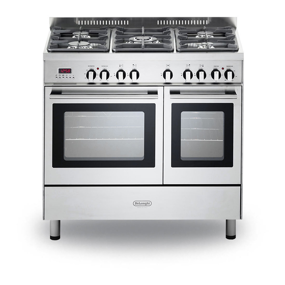
- Page 1 D E’ LO N G HI C OO KIN G USER & INSTALLATION INSTRUCTIONS D S R 90 5- DF DUAL FUEL COOKER...
-
Page 2: Table Of Contents
CONTENTS Page Number Introduction ..........Important Safety Precautions &... -
Page 3: Introduction
Dear Customer, Thank you for purchasing the DeLonghi DSR 905-DF dual fuel cooker. The safety precautions and recommendations listed below are for your own safety and that of others. They will also provide a means by which to make full use of the features offered by your appliance. -
Page 4: Important Safety Precautions & Recommendations
IMPORTANT SAFETY PRECAUTIONS AND RECOMMENDATIONS IMPORTANT: This appliance is designed and manufactured solely for the cooking of domestic (household) food and is not suitable for any non domestic application and therefore should not be used in a commercial environment. The appliance guarantee will be void if the appliance is used within a non domestic environment i.e. - Page 5 • Do not touch the appliance with wet or damp hands (or feet). • Do not use the appliance whilst in bare feet. • If you should decide not to use this appliance any longer (or decide to substitute another model), before disposing of it, it is recommended that it be made inoperative in an appropriate manner in accordance to health and environmental protection regulations, ensuring in particular that all potentially hazardous parts be made harmless, especially in...
- Page 6 • WARNING: Danger of fire: do not store items on the cooking surfaces. • WARNING: When correctly installed, your product meets all safety requirements laid down for this type of product category. However special care should be taken around the rear or the underneath of the appliance as these areas are not designed or intended to be touched and may contain sharp or rough edges, that may cause injury.
-
Page 7: Cooking Hob
1 - COOKING HOB Fig. 1.1 GAS BURNERS Auxiliary burner (A) 1,00 kW Semi-rapid burner (SR) 1,75 kW Rapid burner (R) 3,00 kW Triple-ring burner (TR) 3,50 kW Notes: • The electric ignition is incorporated in the knobs. • The appliance has a safety valve system fitted, the flow of gas will be stopped if and when the flame should accidentally go out. -
Page 8: Control Panel
2 - CONTROL PANEL Fig. 2.1 MULTIFUNCTION CONTROLS DESCRIPTION Front right burner control knob Rear right burner control knob Central burner control knob Rear left burner control knob Front left burner control knob Multifunction oven thermostat control knob Multifunction oven function selector control knob Electronic programmer Pilot lamp: Oven temperature indicator light... -
Page 9: Use Of The Hob Burners
3 - USE OF THE HOB BURNERS GAS BURNERS Gas flow to the burners is adjusted by turning the knobs (illustrated in fig. 3.1) which control the safety valves. Turning the knob, so that the indicator line points to the symbols printed on the panel, achieves the following functions: - symbol closed valve... - Page 10 LIGHTING THE BURNERS CHOICE OF THE BURNER ignite burner, following On the control panel, near every knob instructions are to be followed: there is a diagram that indicates which burner is controlled by that knob. Press in the corresponding knob and The suitable burner must be chosen turn counter-clockwise (fig. 3.2) to the according to the diameter and the capacity...
- Page 11 CORRECT USE OF THE TRIPLE-RING BURNER The flat-bottomed pans are to be placed directly onto the pan-support. When using a WOK you need to place the supplied stand in the burner to avoid any faulty operation of the triple-ring burner (Figs. 3.4a - 3.4b). IMPORTANT: The special grille for wok pans (fig. 3.4b) MUST BE PLACED ONLY over the pan-rest for the triple-ring burner.
-
Page 12: Multifunction Electric Oven
4 - MULTIFUNCTION ELECTRIC OVEN OPERATING PRINCIPLES Attention: The oven door becomes Heating cooking very hot during operation. MULTIFUNCTION oven are obtained in the Keep children away. following ways: by normal convection GENERAL FEATURES The heat is produced by the upper and As its name indicates, this is an oven lower heating elements. - Page 13 MULTIFUNCTION Fig. 4.1 Fig. 4.2 TEMPERATURE KNOB (fig. 4.1) To turn on the heating elements of the oven, set first the function selector to the required setting and then the thermostat knob to the desired temperature. To set the temperature, line up the temperature knob indicator with the required temperature. The elements will turn ON or OFF automatically according to the energy need which is determined by the thermostat.
- Page 14 DEFROSTING FROZEN FOODS Only the oven fan is on. To be used with the thermostat knob on “ ” because the other positions have no effect. The defrosting is done by simple ventilation without heat. Recommended for: To defrost frozen foods. The defrosting times vary according to the quantity and type of foods to be defrosted.
-
Page 15: Oven Temperature Guide
5 - OVEN TEMPERATURE GUIDE Electric oven temperature Cooking process Oven heat Gas mark °C °F Keeping food hot, ½ very cool milk puddings Egg custards cool Rich fruit cakes, cool braising Low temperature moderate roasting, shortbread Victoria sandwich, plain fruit cake, moderate baked fish Small cakes, choux... -
Page 16: Electronic Programmer
6 - ELECTRONIC PROGRAMMER The electronic programmer is a device which groups together the following functions: • 24 hours clock with illuminated display • Timer (up to 23 hours and 59 minutes) • Program for automatic oven cooking • Program for semi-automatic oven cooking Description of the buttons: Description illuminated... - Page 17 ELECTRONIC CLOCK ELECTRONIC TIMER (fig. 6.2) The programmer is equipped with an The timer program consists only of a electronic clock with illuminated numbers buzzer which may be set for a maximum which indicates hours and minutes. period of 23 hours and 59 minutes. Upon immediate connection of the oven or If the AUTO symbol is flashing push the after a power cut, three zeros will flash on...
- Page 18 AUTOMATIC OVEN COOKING Set the temperature and the cooking program by using the switch and To cook food automatically in the oven, it is thermostat knobs of the oven (see necessary to: specific chapters). Set the length of the cooking period. oven programmed Set the end of the cooking time.
- Page 19 SEMI-AUTOMATIC COOKING At the end of the cooking time the oven will turn off automatically, the symbol This is used to automatically switch off the will turn off, AUTO will flash and a buzzer oven after the desired cooking time has will be sound, which can be turned off by elapsed.
-
Page 20: Cleaning & Maintenance
7 - CLEANING AND MAINTENANCE GENERAL ADVICE CLEANING • Before you begin cleaning, you Stainless steel hob: Spillage on • must ensure that the appliance is the hob can usually be removed by switched off at the cooker switch. a damp soapy cloth. More obstinate •... - Page 21 Inside of oven: The oven should BURNERS AND PAN SUPPORTS • always be cleaned after use when it These parts can be removed and cleaned has cooled down. The cavity should be as indicated previously. cleaned using a mild detergent solution After cleaning, the burners and their flame and warm water.
- Page 22 Fig. 7.1 Fig. 7.2 Fig. 7.3 Fig. 7.4 Fig. 7.5...
- Page 23 OVEN FITTING OUT • Assemble the wire racks to the oven walls using the 2 screws (Fig. 7.6). • Slide the rack into the runners (Fig. 7.7). The rack must be fitted so that the safety notch, which stops it sliding out, faces the inside of the oven; the guard rail shall be at the back. •...
- Page 24 REPLACING THE OVEN LAMPS WARNING: Ensure the appliance is switched off before replacing the lamp to avoid the possibility of electric shock. • Let the oven cavity and the heating elements to cool down. • Switch off the electrical supply. •...
- Page 25 REMOVING AND REPLACING THE INNER DOOR GLASS PANE FOR CLEANING If you wish to clean the inner glass of the door, make sure you follow the precautions and instructions very carefully. Replacing the glass pane and the door incorrectly may result in damage to the appliance and may void your warranty.
- Page 26 REMOVING THE OVEN DOOR The oven door can easily be removed as follows: • Open the door to the full extent (fig. 7.10). • Open the lever “A” completely on the left and right hinges (fig. 7.11). • Hold the door as shown in fig. 7.13. • Fig. 7.10 Gently close the door (fig. 7.12) until left and right hinge levers “A” are hooked to part “B” of the door (fig. 7.11).
- Page 27 REMOVING THE INNER PANE OF GLASS The oven door is fitted with no. 2 panes: • no. 1 outside; • no. 1 inner. To clean all panes on both sides it is necessary to remove the inner pane as follows: REMOVE THE INNER GLASS RETAINER Remove the oven door and place it on a soft surface. IMPORTANT: The door shall be placed horizontally as per Fig.
- Page 28 REMOVE THE INNER GLASS PANE Lift and remove the inner pane slightly, as shown in the figure 7.16. Fig. 7.16...
- Page 29 AFTER CLEANING, REPLACE THE INNER GLASS PANE When replacing the inner glass pane, make sure that: • You replace the pane correctly, as shown. The pane must be in the position described below in order to fit into the door and to ensure that the appliance operates safely and correctly. • You take extra care not to bump the edges of the glass against any object or surface. •...
- Page 30 REPLACE THE GLASS RETAINER Position the glass retainer, as shown in the figure 7.18. It should sit on the bottom edge of the outer glass. Check that the clamps “M” are not deformed or damaged. Gently push the glass retainer back into place. You should be able to hear the tabs on both sides click as they lock the glass retainer in. Important ! Make sure the glass retainer is correctly and firmly in place and that the glass pane is secure.
- Page 31 REFIT THE DOOR Hold the door firmly (fig. 7.19). Insert the hinge tongues into the slots, making sure that the groove drops into place as shown in the figure 7.20. Open the door to its full extent. Fully close the levers “A” on the left and right hinges, as shown in the figure 7.21. Close the door and check that it is properly in place. Fig.
-
Page 32: Advice For The Installer
Advice for the installer IMPORTANT • The appliance is designed and approved for domestic use only and should not be installed in a commercial, semi commercial or communal environment. Your product will not be guaranteed if installed in any of the above environments and could affect any third party or public liability insurances you may have. -
Page 33: Installation
8 - INSTALLATION This cooker has class “2/1” overheating protection so that it can be installed next to a cabinet. If the cooker is installed adjacent to furniture which is higher than the gas hob cooktop, a gap of at least 200 mm must be left between the side of the cooker and the furniture. The walls and kitchen furniture surrounding the appliance must be made of non-flammable material. - Page 34 BACKGUARD Before installing cooker, assemble the backguard “C” (fig. 8.2). • The backguard “C” can be found packed at the rear of the cooker. • Before assembling remove any protective film/adhesive tape. • Remove the two spacers “A” and the screw “B” from the rear of the cooktop.
- Page 35 MOVING THE COOKER WARNING: When raising cooker to upright position always ensure two people carry out this manoeuvre to prevent damage to the adjustable feet (fig. 8.5). Fig. 8.5 WARNING WARNING Be carefull: Do not lift the cooker by When moving cooker to its final position the door handle/s when raising to the DO NOT DRAG (fig. 8.7). upright position (fig. 8.6). Lift feet clear of floor (fig. 8.5). Fig. 8.7 Fig.
- Page 36 ANTI-TILT BRACKET Important! To restrain the appliance and prevent it tipping accidentally, fit the supplied bracket to the rear wall to fix it securely. To fit the anti-tilt bracket: After you have located where the cooker is to be positioned, mark on the wall the place where the two screws of the anti-tilt bracket have to be fitted. Please follow the indications given in fig. 8.8. Drill two 8 mm diameter holes in the wall and insert the plastic plugs supplied. Important! Before drilling the holes, check that you will not damage any pipes or electrical wires.
-
Page 37: Provision For Ventilation
PROVISION FOR VENTILATION • The appliance should be installed into a room or space with an air supply in accordance with the current version of BS 5440-2: 2000. • For rooms with a volume of less than 5m - permanent ventilation of 100 cm free area must be provided. -
Page 38: Gas Installation
9 - GAS INSTALLATION IMPORTANT NOTE This appliance is supplied for use on NATURAL GAS or LPG (check the gas regulation label attached on the appliance). • Appliances supplied for use on NATURAL GAS are adjusted for this gas only and cannot be used on any other gas (LPG) without modification. The appliances are manufactured for conversion to LPG. - Page 39 RESTRAINING CHAIN Fig. 9.1 Chain security holes Cooker Back of the cooker Rear wall Installation to Natural Gas Installation to Natural Gas must conform to the Code of Practice, etc. The supply pressure for Natural Gas is 20 mbar. The installation must conform to the relevant British/European Standards. Installation to LP Gas When operating on Butane gas a supply pressure of 28-30 mbar is required.
- Page 40 Notes: • Flexible hoses can be used where the sited ambient temperature of the hose does not exceed 70°C. These hoses must be manufactured in accordance with BS669 part 1 and be of the correct construction for the type of gas being used. •...
- Page 41 Fitting the plug Fig. 9.3 on the inlet pipe terminal not used Cooker manifold (right Cooker or left inlet pipe) manifold (right or left inlet pipe) Manifold male Manifold pipe fitting male 1/2” G cylindrical pipe fitting (ISO 228-1) male 1/2” G cylindrical (ISO 228-1) male Fibre Fibre...
- Page 42 CONVERSION TO NATURAL GAS OR TO LPG REPLACEMENT Auxiliary, INJECTORS OF THE TOP BURNERS Semi-rapid and If the injectors are not supplied they can Rapid burners be obtained from the After-Sales Service. Select the injectors to be replaced according to the “Table for the choice of the injectors”.
- Page 43 TABLE FOR THE CHOICE OF THE INJECTORS Cat: 2H3+ Natural Gas G30 28-30 mbar Nominal Reduced G20 20 mbar G31 37 mbar BURNERS Power Power [Hs - kW] [Hs - kW] Ø injector Ø injector [1/100 mm] [1/100mm] Auxiliary (A) 1,00 0,30 72 (X)
-
Page 44: Electrical Installation
10 - ELECTRICAL INSTALLATION IMPORTANT: The appliance must be installed in accordance with the manufacturer’s instructions. Incorrect installation, for which the manufacturer accepts no responsibility, may cause damage to persons, animals and property. The connection of the appliance to earth is mandatory. The manufacturer declines all responsibility for any inconvenience resulting from the inobservance of this condition. - Page 45 CONNECTION OF THE POWER SUPPLY CABLE • Unhook the terminal board cover by inserting a screwdriver into the two hooks “A” (fig. 10.2). • Open the cable gland by unscrewing screw “F” (fig. 10.3), unscrew the terminal screws. • Insert the feeder cable of the suitable section (as described in the next chapter) into the cable gland.
- Page 46 11 - GUARANTEE Your new “De’Longhi” product comes with 12-month guarantee covering all parts and labour. If your appliance proves to be defective as a result of faulty materials or workmanship during the guarantee period, these parts will be repaired or replaced free of charge. AFTER SALES SERVICE Should you require service, spares or product information and advice: •...
- Page 48 D esc ri pt i o n s an d i ll ustrations i n this book let are gi ven a s s im p ly i nd ica ti ve . T he m an u f ac t u re r re serves the right, considering th e ch a ra cter is tics o f the model s d es c ri be d he re, at any ti me and wi thout notice, to ma ke even tua l n ecess a ry modifi c at i o n s f o r t he i r construction or for co mm erci al n eed s.