Table of Contents
Advertisement
Intel
Technical Product Specification
®
The Intel
Desktop Board D815EEA may contain design defects or errors known as errata that may cause the product to deviate from published specifications. Current
characterized errata are documented in the Intel Desktop Board D815EEA Specification Update.
Desktop Board D815EEA
®
May 2000
Order Number A16964 –001
Advertisement
Table of Contents

Related Manuals for Intel D815EEA


Summary of Contents for Intel D815EEA
- Page 1 Order Number A16964 –001 ® The Intel Desktop Board D815EEA may contain design defects or errors known as errata that may cause the product to deviate from published specifications. Current characterized errata are documented in the Intel Desktop Board D815EEA Specification Update.
-
Page 2: Revision History
Contact your local Intel sales office or your distributor to obtain the latest specifications before placing your product order. Copies of documents which have an ordering number and are referenced in this document, or other Intel literature, may be obtained from: Intel Corporation P.O. -
Page 3: Intended Audience
Intended Audience The TPS is intended to provide detailed, technical information about the D815EEA board and its components to the vendors, system integrators, and other engineers and technicians who need this level of information. It is specifically not intended for general audiences. - Page 4 When used in the description of a component, N indicates component type, xn are the relative coordinates of its location on the D815EEA board, and X is the instance of the particular part at that general location. For example, J5J1 is a connector, located at 5J. It is the first connector in the 5J area.
-
Page 5: Table Of Contents
1 Product Description Overview ........................12 1.1.1 Feature Summary ..................12 1.1.2 Manufacturing Options ................13 1.1.3 D815EEA Board Layout ................14 1.1.4 Block Diagram ..................... 15 Online Support......................16 Design Specifications ....................16 Processor ........................19 System Memory......................20 ®... - Page 6 ® Intel Desktop Board D815EEA Technical Product Specification 2 Technical Reference Introduction........................ 47 Memory Map ......................47 I/O Map ........................48 DMA Channels ......................50 PCI Configuration Space Map ................... 50 Interrupts ........................51 PCI Interrupt Routing Map ..................51 Connectors ........................
- Page 7 Figures D815EEA Board Components ................... 14 Block Diagram ......................15 Intel 815E Chipset Block Diagram ................22 Block Diagram of Basic Audio Subsystem ..............33 Block Diagram of Enhanced PCI Audio Subsystem ........... 33 ICH2 and CNR Signal Interface ................. 37 Using the Wake on LAN Technology Connector ............
- Page 8 ® Intel Desktop Board D815EEA Technical Product Specification D815EEA Board Dimensions..................75 I/O Shield Dimensions ....................76 Localized High Temperature Zones ................81 Diagnostic LEDs ...................... 125 Tables Feature Summary...................... 12 Manufacturing Options....................13 Specifications ......................16 Supported Processors ....................19 Supported Memory Configurations ................
- Page 9 Power Usage For Board with Enhanced PCI Audio Subsystem and no Onboard LAN subsystem..................78 Standby Current Requirements ................. 79 Thermal Considerations for Components ..............82 D815EEA Board Environmental Specifications ............83 Safety Regulations ....................84 EMC Regulations....................... 84 Supervisor and User Password Functions ..............95 BIOS Setup Program Menu Bar.................
- Page 10 ® Intel Desktop Board D815EEA Technical Product Specification...
-
Page 11: Product Description
Overview ........................12 Online Support......................16 Design Specifications ....................16 Processor ........................19 System Memory......................20 ® Intel 815E Chipset ....................22 I/O Controller ......................26 Graphics Subsystem ....................28 Audio Subsystem (Optional) ..................32 1.10 LAN Subsystem......................35 1.11 CNR (Optional) ......................36 1.12 Hardware Management Subsystem (Optional) ............ -
Page 12: Overview
• Five PCI bus add-in card connectors (SMBus routed to PCI bus connector 2) Expansion Capabilities • One AGP universal connector • Intel/AMI BIOS (resident in the Intel 82802AB 4 Mbit FWH) BIOS • Support for Advanced Power Management (APM), Advanced Configuration and Power Interface (ACPI), Plug and Play, and SMBIOS... -
Page 13: Manufacturing Options
Product Description 1.1.2 Manufacturing Options Table 2 describes the D815EEA board’s manufacturing options. Table 2. Manufacturing Options Audio Two separate Audio Codec ’97 (AC ’97) compatible audio subsystem options: • A basic audio subsystem that includes the ICH2 component and an Analog Devices AD1885 analog codec, or •... -
Page 14: D815Eea Board Layout
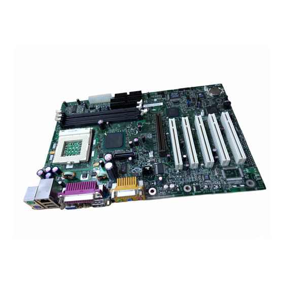
® Intel Desktop Board D815EEA Technical Product Specification 1.1.3 D815EEA Board Layout Figure 1 shows the location of the major components on the D815EEA board. OM10041 Creative Labs ES1373 Digital Controller IDE connectors (optional) Serial port B connector AD1885 audio codec (optional) -
Page 15: Block Diagram
Product Description 1.1.4 Block Diagram Figure 2 is a block diagram of the major functional areas of the D815EEA board. Diagnostic LEDs Primary/ ATA-33/66/100 Secondary IDE USB Ports 0 and 1 Processor Socket System Bus USB Ports 2 and 3... -
Page 16: Online Support
World Wide Web sites: http://www.intel.com/design/motherbd http://support.intel.com/support/motherboards/desktop ® Find “Processor Data Sheets” or information about “Proper Date Access in Systems with Intel Motherboards” at these World Wide Web sites: http://www.intel.com/design/litcentr http://support.intel.com/support/year2000 Find information about the ICH addressing at this World Wide Web site: http://developer.intel.com/design/chipsets/datashts/... - Page 17 PCI Bus Power Version 1.1, http://www.pcisig.com/ Management Interface December 18, 1998, Specification PCI Special Interest Group. Plug and Play BIOS Plug and Version 1.0a, http://www.microsoft.com/ Play specification May 5, 1994, hwdev/respec/ Compaq Computer Corp., pnpspecs.htm Phoenix Technologies Ltd., and Intel Corporation. continued...
- Page 18 ® Intel Desktop Board D815EEA Technical Product Specification Table 3. Specifications (continued) Specification Version, Revision Date The information is Description Title and Ownership available from… SDRAM PC SDRAM Unbuffered Revision 1.0, http://www.intel.com/ DIMM Specification February, 1998, design/chipsets/memory Intel Corporation. PC SDRAM DIMM Revision 1.5,...
-
Page 19: Processor
1.4 Processor CAUTION The D815EEA board supports processors that have an 18.2 A maximum current draw with a 1.65 to 2.0 V core voltage. Using a processor not in compliance with the above guidelines can damage the processor, the D815EEA board, and the power supply. See the processor’s data sheet for voltage and current usage requirements. -
Page 20: System Memory
® Intel Desktop Board D815EEA Technical Product Specification 1.5 System Memory The D815EEA board has three DIMM sockets and supports the following memory features: • 3.3 V (only) 168-pin SDRAM DIMMs with gold-plated contacts • Unbuffered single- or double-sided DIMMs •... -
Page 21: Supported Memory Configurations
Front side population / back side population indicated for SDRAM density and SDRAM organization. CAUTION ® To be fully compliant with all applicable Intel SDRAM memory specifications, the motherboard should be populated with DIMMs that support the Serial Presence Detect (SPD) data structure. If your memory modules do not support SPD, you will see a notification to this effect on the screen at power up. -
Page 22: Intel ® 815E Chipset
Intel Desktop Board D815EEA Technical Product Specification ® 1.6 Intel 815E Chipset The Intel 815E chipset consists of the following devices: • 82815E Graphics and Memory Controller Hub (GMCH) with Accelerated Hub Architecture (AHA) bus • 82801BA I/O Controller Hub (ICH2) with AHA bus •... -
Page 23: Intel ® 82815E Graphics And Memory Controller Hub (Gmch)
Product Description ® 1.6.1 Intel 82815E Graphics and Memory Controller Hub (GMCH) The GMCH provides the following: • An integrated Synchronous DRAM memory controller with autodetection of SDRAM • An interface for a single AGP device or a Graphics Performance Accelerator (GPA) card •... - Page 24 Table 76, page 114 1.6.2.2 The ICH2 contains two separate USB controllers. The D815EEA board has four USB ports; one USB peripheral can be connected to each port. For more than four USB devices, an external hub can be connected to any of the ports. Two of the USB ports are implemented with stacked back panel connectors;...
-
Page 25: Intel ® 82802Ab 4 Mbit Firmware Hub (Fwh)
The recommended method of accessing the date in systems with D815EEA boards is indirectly from the Real-Time Clock (RTC) via the BIOS. The BIOS on D815EEA boards contains a century checking and maintenance feature. This feature checks the two least significant digits of the year stored in the RTC during each BIOS request (INT 1Ah) to read the date and, if less than 80 (i.e.,... -
Page 26: I/O Controller
1.7.1 Serial Ports The D815EEA board has two serial ports. Serial port A is located on the back panel. Serial port B is accessible using the connector at location J8E1. The serial ports’ NS16C550-compatible UARTs support data transfers at speeds up to 115.2 kbits/sec with BIOS support. The serial ports can be assigned as COM1 (3F8h), COM2 (2F8h), COM3 (3E8h), or COM4 (2E8h). -
Page 27: Parallel Port
Product Description For information about Refer to The location of the front panel connector Figure 12, page 69 The signal names of the front panel connector Table 48, page 71 Configuring serial port B for infrared applications Section 4.4.3, page 104 The IrDA specification Section 1.3, page 16 1.7.3 Parallel Port... -
Page 28: Graphics Subsystem
® Intel Desktop Board D815EEA Technical Product Specification For information about Refer to The location of the keyboard and mouse connectors Figure 9, page 54 The signal names of the keyboard and mouse connectors Table 18, page 55 1.8 Graphics Subsystem The 815E chipset contains two separate, mutually exclusive graphics options. -
Page 29: Supported Graphics Refresh Frequencies
Product Description Table 6. Supported Graphics Refresh Frequencies Available Refresh Resolution Color Palette Frequencies (Hz) Notes 256 colors 320 x 200 64 K colors 16 M colors 256 colors 320 x 240 64 K colors 16 M colors 256 colors 352 x 480 64 K colors 16 M colors... -
Page 30: Digital Video Output (Dvo) Connector
1.8.2 Digital Video Output (DVO) Connector The board routes the Intel 82815E GMCH DVO port to an onboard 40-pin DVO connector. The DVO connector can be cabled to a DVI or TV out card to enable digital displays or TV out functionality. -
Page 31: Agp Universal Connector
Graphics Performance Accelerator (GPA) Support The Intel 815E GMCH display cache is a single channel 32-bit wide SDRAM interface. The 4 MB display cache resides on a GPA card that plugs into the AGP connector. The BIOS detects a GPA card if present in the AGP port and initializes it as display cache memory. -
Page 32: Audio Subsystem (Optional)
Obtaining the Accelerated Graphics Port Interface Specification Section 1.3, page 16 1.9 Audio Subsystem (Optional) The D815EEA board offers two separate audio subsystems. Both audio subsystems include these features: • Split digital/analog architecture for improved S/N (signal-to-noise) ratio: ≥ 85 dB •... -
Page 33: Enhanced Pci Audio Subsystem
Figure 4. Block Diagram of Basic Audio Subsystem 1.9.2 Enhanced PCI Audio Subsystem The D815EEA board offers an optional subsystem of AC ’97 V 1.03 compliant audio features supported by the Creative Labs ES1373 digital controller with Crystal Semiconductor CS4297 (A) codec. -
Page 34: Audio Connectors
® Intel Desktop Board D815EEA Technical Product Specification • Crystal Semiconductor CS4297 (A) Stereo Audio Codec: 20-bit stereo digital-to-analog and 18-bit stereo analog-to-digital converters High performance 18-bit stereo full-duplex audio codec with up to 48 kHz sampling rate ... -
Page 35: Lan Subsystem
Product Description 1.9.3.2 ATAPI CD-ROM Audio Connector A 1 x 4-pin ATAPI-style connector connects an internal ATAPI CD-ROM drive to the audio mixer. For information about Refer to The location of the ATAPI CD-ROM connector Figure 10, page 59 The signal names of the ATAPI CD-ROM connector Table 30, page 60 1.9.3.3 Telephony Connector... -
Page 36: Intel ® 82562Et Platform Lan Connect Device (Optional)
Obtaining LAN software and drivers Section 1.2, page 16 1.11 CNR (Optional) The CNR connector supports the audio, modem, USB, and LAN interfaces of the Intel 815E chipset. Figure 6 shows the signal interface between the riser and the ICH2. -
Page 37: Hardware Management Subsystem (Optional)
Product Description AC ’97 Interface Communication and LAN Interfaces Networking Riser Intel 82801BA I/O Controller Hub SMBus (Up to two AC ’97 codecs (ICH2) and one LAN device) Power OM10412 Figure 6. ICH2 and CNR Signal Interface NOTE The USB interface from the ICH2 to the CNR is not supported on this board. -
Page 38: Hardware Monitor Component
® Intel Desktop Board D815EEA Technical Product Specification 1.12.1 Hardware Monitor Component The hardware monitor component provides low-cost instrumentation capabilities. The features of the component include: • Internal ambient temperature sensing • Remote thermal diode sensing for direct monitoring of processor temperature (if supported in the processor) •... -
Page 39: Power Management
• • ACPI If the D815EEA board is used with an ACPI-aware operating system, the BIOS can provide ACPI support. Otherwise, it defaults to APM support. 1.13.1.1 APM makes it possible for the computer to enter an energy-saving standby mode. The standby mode can be initiated in the following ways: •... -
Page 40: Effects Of Pressing The Power Switch
ACPI ACPI gives the operating system direct control over the power management and Plug and Play functions of a computer. The use of ACPI with the D815EEA board requires an operating system that provides full ACPI support. ACPI features include: •... -
Page 41: Power States And Targeted System Power
The operating system uses information from applications and user settings to put the system as a whole into a low-power state. Table 9 lists the power states supported by the D815EEA board along with the associated system power targets. See the ACPI specification for a complete description of the various system and power states. -
Page 42: Hardware Support
Plug and Play device enumeration and configuration. ACPI is used only to enumerate and configure D815EEA board devices that do not have other hardware standards for enumeration and configuration. PCI devices on the D815EEA board, for example, are not enumerated by ACPI. -
Page 43: Fan Connector Descriptions
The BIOS Setup program’s Boot menu Table 76, page 114 The ATX specification Section 1.3, page 16 1.13.2.2 Fan Connectors The D815EEA board has three fan connectors. The functions of these connectors are described in Table 11. Table 11. Fan Connector Descriptions Connector Function System fan (fan 1) Provides +12 V DC for a system or chassis fan. -
Page 44: Using The Wake On Lan Technology Connector
† Upon detecting a Magic Packet frame, the LAN subsystem asserts a wakeup signal that powers up the computer. Depending on the LAN implementation, the D815EEA board supports Wake on LAN technology in the following ways: • Through the Wake on LAN technology connector (APM only) •... -
Page 45: Location Of Standby Power Indicator Led
Instantly Available technology can damage the power supply. Refer to Section 2.11.3 on page 78 for additional information. Instantly Available technology enables the D815EEA board to enter the ACPI S3 (Suspend-to- RAM) sleep-state. While in the S3 sleep-state, the computer will appear to be off (the power supply is off, the fans are off, and the front panel LED is amber if dual-color, or off if single- color.) When signaled by a wake-up device or event, the system quickly returns to its last known... - Page 46 ® Intel Desktop Board D815EEA Technical Product Specification 1.13.2.5 Resume on Ring The operation of Resume on Ring can be summarized as follows: • Resumes operation from either the APM sleep mode or the ACPI S1 state • Requires only one call to access the computer •...
-
Page 47: Technical Reference
2 Technical Reference What This Chapter Contains Introduction........................ 47 Memory Map ......................47 I/O Map ........................48 DMA Channels ......................50 PCI Configuration Space Map ................... 50 Interrupts ........................51 PCI Interrupt Routing Map ..................51 Connectors ........................ 53 Jumper Block......................73 2.10 Mechanical Considerations.................. -
Page 48: I/O Map
® Intel Desktop Board D815EEA Technical Product Specification 2.3 I/O Map Table 13. I/O Map Address (hex) Size Description 0000 - 000F 16 bytes DMA controller 0020 - 0021 2 bytes Programmable Interrupt Control (PIC) 0040 - 0043 4 bytes... - Page 49 Secondary bus master IDE registers 96 contiguous bytes starting on a 128-byte ICH (ACPI + TCO) divisible boundary 64 contiguous bytes starting on a 64-byte D815EEA board resource divisible boundary 64 contiguous bytes starting on a 64-byte Onboard audio controller divisible boundary...
-
Page 50: Dma Channels
® Intel Desktop Board D815EEA Technical Product Specification 2.4 DMA Channels Table 14. DMA Channels DMA Channel Number Data Width System Resource 8- or 16-bits Audio 8- or 16-bits Audio / parallel port 8- or 16-bits Diskette drive 8- or 16-bits... -
Page 51: Interrupts
Technical Reference 2.6 Interrupts Table 16. Interrupts System Resource I/O channel check Reserved, interval timer Reserved, keyboard buffer full Reserved, cascade interrupt from slave PIC COM2 (Note) COM1 (Note) LPT2 (Plug and Play option) / Audio / User available Diskette drive LPT1 (Note) Real-time clock Reserved for ICH system management bus... -
Page 52: Pci Interrupt Routing Map
D815EEA board and therefore share the same interrupt. Table 17 shows an example of how the PIRQ signals are routed on the D815EEA board. For example, using Table 17 as a reference, assume an add-in card using INTA is plugged into PCI bus connector 4. -
Page 53: Connectors
2.8 Connectors CAUTION Only the back panel connectors of the D815EEA board have overcurrent protection. The D815EEA board’s internal connectors are not overcurrent protected and should connect only to devices inside the computer’s chassis, such as fans and internal peripherals. Do not use these connectors to power devices external to the computer’s chassis. -
Page 54: Back Panel Connectors
® Intel Desktop Board D815EEA Technical Product Specification 2.8.1 Back Panel Connectors Figure 9 shows the location of the back panel connectors. The back panel connectors are color- coded in compliance with PC 99 recommendations. The figure legend below lists the colors used. -
Page 55: Ps/2 Mouse/Keyboard Connectors
Technical Reference NOTE The back panel audio line out connector is designed to power headphones or amplified speakers only. Poor audio quality occurs if passive (non-amplified) speakers are connected to this output. Table 18. PS/2 Mouse/Keyboard Connectors Signal Name Data Not connected Ground Fused +5 V... -
Page 56: Vga Port Connector
® Intel Desktop Board D815EEA Technical Product Specification Table 21. VGA Port Connector Signal Name Signal Name Signal Name Ground No connect Green Ground MONID1 Blue Ground HSYNC No connect Fused VCC VSYNC Ground Ground MONID2 Table 22. Parallel Port Connector... -
Page 57: Midi/Game Port Connector
Technical Reference Table 24. MIDI/Game Port Connector Signal Name Signal Name +5 V (fused) +5 V (fused) JOY4 JOY6 JOYTIME0 JOYTIME2 Ground MIDI-OUT Ground JOYTIME3 JOYTIME1 JOY7 JOY5 MIDI-IN +5 V (fused) Table 25. Audio Line Out Connector Signal Name Audio left out Ring Audio right out... -
Page 58: Internal I/O Connectors
® Intel Desktop Board D815EEA Technical Product Specification 2.8.2 Internal I/O Connectors The internal I/O connectors are divided into the following functional groups: • Audio, video, power, and hardware control (see page 59) ATAPI CD-ROM Legacy style (2-mm) CD-ROM ... -
Page 59: Audio, Video, Hardware Control, And Fan Connectors
Technical Reference 2.8.2.2 Audio, Video, Power, and Hardware Control Connectors Figure 10 shows the location of the audio, video, power, and hardware control connectors. OM10044 Item Description Color Reference Designator For more information see: Chassis Fan (Fan 2) J3F1 Table 28 CD-ROM, Legacy style, 2 mm White J2F2... -
Page 60: Chassis Fan Connector (J3F1)
® Intel Desktop Board D815EEA Technical Product Specification For information about Refer to The power connector Section 1.13.2.1, page 43 The functions of the fan connectors Section 1.13.2.2, page 43 Wake on LAN technology Section 1.13.2.3, page 44 Table 28. -
Page 61: Digital Video Out Connector (J3H1)
Technical Reference Table 33. Digital Video Out Connector (J3H1) Signal Name Signal Name LTVCLKIN +5 VDC P_RST_SLOTS# LTVCL_3V Ground LTVDA_3V Ground LTVVSYNC Ground LTVHSYNC Ground LTVDAT0 Ground LTVDAT1 Ground LTVDAT2 Ground LTVDAT3 Ground LTVDAT4 Ground LTVDAT5 Ground LTVDAT6 Ground LTVDAT7 Ground LTVDAT8 Ground... -
Page 62: Wake On Lan Technology Connector (J6B1)
® Intel Desktop Board D815EEA Technical Product Specification Table 36. Wake on LAN Technology Connector (J6B1) Signal Name +5 VSB Ground Table 37. Chassis Intrusion Connector (J7B1) Signal Name INTRUDER# Ground Table 38. Chassis Fan Connector (J8B1) Signal Name FAN1_PWM... -
Page 63: Add-In Board And Peripheral Interface Connectors
Technical Reference 2.8.2.3 Add-in Board and Peripheral Interface Connectors Figure 11 shows the location of the add-in board connector and peripheral connectors. Note the following considerations for the PCI bus connectors: • All of the PCI bus connectors are bus master capable. •... -
Page 64: Cnr Connector (J3A1)
® Intel Desktop Board D815EEA Technical Product Specification Table 39. CNR Connector (J3A1) Signal Name Signal Name Reserved Reserved Reserved Reserved Ground Reserved Reserved Ground Reserved Reserved Ground Reserved LAN_TXD2 Ground LAN_TXD0 LAN_TXD1 Ground LAN_RSTSYNC LAN_CLK Ground LAN_RXD1 LAN_RXD2 Reserved... -
Page 65: Pci Bus Connectors (J4A1, J4B1, J4C1, J4D1, J4E1)
Technical Reference Table 40. PCI Bus Connectors (J4A1, J4B1, J4C1, J4D1, J4E1) Signal Name Signal Name Signal Name Signal Name Ground (TRST#)* -12 V AD16 AD17 +12 V Ground (TCK)* +3.3 V C/BE2# +5 V (TMS)* Ground FRAME# Ground +5 V (TDI)* no connect (TDO)* Ground IRDY#... -
Page 66: Agp Universal Connector (J5E1)
® Intel Desktop Board D815EEA Technical Product Specification Table 41. AGP Universal Connector (J5E1) Signal Name Signal Name Signal Name Signal Name +12V No Connect Vcc3.3 Vcc3.3 TYPEDET# AD22 AD21 Reserved AD20 AD19 No Connect No Connect Ground Ground Ground... -
Page 67: Diskette Drive Connector (J8G3)
Technical Reference Table 42. Diskette Drive Connector (J8G3) Signal Name Signal Name Ground DENSEL Ground Reserved FDEDIN Ground FDINDX# (Index) Ground FDM00# (Motor Enable A) Ground No connect Ground FDDS0# (Drive Select A) Ground No connect No connect FDDIR# (Stepper Motor Direction) Ground FDSTEP# (Step Pulse) Ground... -
Page 68: Pci Ide Connectors (J8G2, Primary And J6G1, Secondary)
® Intel Desktop Board D815EEA Technical Product Specification Table 43. PCI IDE Connectors (J8G2, Primary and J6G1, Secondary) Signal Name Signal Name Reset IDE Ground Data 7 Data 8 Data 6 Data 9 Data 5 Data 10 Data 4 Data 11... -
Page 69: External I/O Connectors
Technical Reference 2.8.3 External I/O Connectors Figure 12 shows the locations of the external I/O connectors. OM10046 Item Description Reference Designator For more information see: SCSI LED J7A1 Table 46 Auxiliary front panel power LED J8C2 Table 47 Front panel J8C3 Table 48 Front panel USB... -
Page 70: Front Panel Usb Connector (J8C1)
® Intel Desktop Board D815EEA Technical Product Specification Table 44. Front Panel USB Connector (J8C1) Signal Name Signal Name VREG_FP_USB_PWR VREG_FP_USB_PWR ICH_U_P2# ICH_U_P3# ICH_U_P2 ICH_U_P3 Ground Ground Key (no pin) ICU_U_OC1_2# Table 45. Serial Port B Connector (J8E1) Signal Name... -
Page 71: Front Panel Connector (J8C3)
2.8.3.3.2 Reset Switch Connector Pins 5 and 7 can be connected to a momentary SPST type switch that is normally open. When the switch is closed, the D815EEA board resets and runs the POST. 2.8.3.3.3 Hard Drive Activity LED Connector Pins 1 and 3 can be connected to an LED to provide a visual indicator that data is being read from or written to a hard drive. -
Page 72: States For A Single-Colored Power Led
SW_ON# pin to ground for at least 50 ms to signal the power supply to switch on or off. (The time requirement is due to internal debounce circuitry on the D815EEA board.) At least two seconds must pass before the power supply will recognize another on/off signal. -
Page 73: Jumper Block
Technical Reference 2.9 Jumper Block CAUTION Do not move any jumpers with the power on. Always turn off the power and unplug the power cord from the computer before changing a jumper setting. Otherwise, the board could be damaged. Figure 13 shows the location of the jumper block. This 3-pin jumper block determines the BIOS Setup program’s mode. -
Page 74: Bios Setup Configuration Jumper Settings (J7B1)
® Intel Desktop Board D815EEA Technical Product Specification Table 51. BIOS Setup Configuration Jumper Settings (J7B1) Function/Mode Jumper Setting Configuration Normal The BIOS uses current configuration information and passwords for booting. Configure After the POST runs, Setup runs automatically. The maintenance menu is displayed. -
Page 75: Mechanical Considerations
2.10 Mechanical Considerations 2.10.1 Form Factor The D815EEA board is designed to fit into an ATX-form-factor chassis. Figure 14 illustrates the mechanical form factor for the D815EEA board. Dimensions are given in inches [millimeters]. The outer dimensions are 8.20 inches by 12.00 inches [208.20 millimeters by 304.80 millimeters]. -
Page 76: I/O Shield
Desktop Board D815EEA Technical Product Specification 2.10.2 I/O Shield The back panel I/O shield for the D815EEA board must meet specific dimension and material requirements. Systems based on this board need the back panel I/O shield to pass certification testing. Figure 15 shows the critical dimensions of the chassis-dependent I/O shield. Dimensions are given in inches, to a tolerance of ±0.02 inches. -
Page 77: Electrical Considerations
ATX Form Factor Specification document (see Table 3 on page 16 for specification information). Table 52 lists the power usage for a D815EEA board with the configuration listed above and including the basic audio subsystem and the onboard LAN subsystem. -
Page 78: Add-In Board Considerations
0.09 A 2.11.2 Add-in Board Considerations The D815EEA board is designed to provide 2 A (average) of +5 V current for each add-in board. The total +5 V current draw for add-in boards in a fully-loaded D815EEA board (all six expansion slots filled) must not exceed 12 A. -
Page 79: Fan Connector Current Capability
CNR requirements are calculated as follows: • One wake-enabled device @ 375 mA • Non wake-enabled devices @ 20 mA 2.11.4 Fan Connector Current Capability The D815EEA board is designed to supply a maximum of 225 mA per fan connector. -
Page 80: Power Supply Considerations
System integrators should refer to the power usage values listed in Section 2.11.1, on page 77 when selecting a power supply for use with the D815EEA board. Measurements account only for current sourced by the D815EEA board while running in idle modes of the started operating systems. -
Page 81: Localized High Temperature Zones
Failure to do so may result in damage to the voltage regulator circuit. Figure 16 shows the locations of the localized high temperature zones. OM10049 Processor voltage regulator area Processor Intel 82815E GMCH Intel 82801BA ICH2 Creative Labs ES1373 digital controller Figure 16. Localized High Temperature Zones... -
Page 82: Reliability
Intel Desktop Board D815EEA Technical Product Specification Table 55 provides maximum case temperatures for D815EEA board components that are sensitive to thermal changes. Case temperatures could be affected by the operating temperature, current load, or operating frequency. Maximum case temperatures are important when considering proper airflow to cool the D815EEA board. -
Page 83: Environmental
Technical Reference 2.14 Environmental Table 56 lists the environmental specifications for the D815EEA board. Table 56. D815EEA Board Environmental Specifications Parameter Specification Temperature -40 °C to +70 °C Non-Operating 0 °C to +55 °C Operating Shock Unpackaged 30 g trapezoidal waveform... -
Page 84: Regulatory Compliance
Summary of Nordic deviations to EN 60950. (Norway, Sweden, Denmark, and Finland) 2.15.2 EMC Regulations Table 58 lists the EMC regulations with which the D815EEA board complies when it is correctly installed in a compatible host system. Table 58. EMC Regulations... -
Page 85: Certification Markings
• PB Part Number: Intel bare circuit board part number (Solder side) PBA10641-001 • Battery “+ Side Up” marking: located on the component side of the D815EEA board in close proximity to the battery holder • FCC Logo/Declaration: (Solder side) •... - Page 86 ® Intel Desktop Board D815EEA Technical Product Specification...
-
Page 87: Overview Of Bios Features
3.10 BIOS Security Features ..................... 94 3.1 Introduction The D815EEA board uses an Intel/AMI BIOS, which is stored in flash memory and can be updated using a disk-based program. In addition to the BIOS, the flash memory contains the BIOS Setup program, POST, APM, the PCI auto-configuration utility, and Plug and Play support. -
Page 88: Bios Flash Memory Organization
Desktop Board D815EEA Technical Product Specification 3.2 BIOS Flash Memory Organization The Intel 82802AB Firmware Hub (FWH) includes a 4 Mbit (512 KB) symmetrical flash memory device. Internally, the device is grouped into eight 64-KB blocks that are individually erasable, lockable, and unlockable. -
Page 89: System Management Bios (Smbios)
The MIF database defines the data and provides the method for accessing this ® ® information. The BIOS enables applications such as Intel LANDesk Client Manager to use SMBIOS. The BIOS stores and reports the following SMBIOS information: •... -
Page 90: Usb Legacy Support
BIOS. This process is fault tolerant to prevent boot block corruption. The BIOS boot block may also be updated separately if selected in the update menu. BIOS upgrades and the Intel Flash Memory Update Utility are available from Intel through the Intel World Wide Web site. -
Page 91: Language Support
During POST, an Intel splash screen is displayed by default. This splash screen can be replaced with a custom splash screen. A utility is available from Intel to assist with creating a custom splash screen. The custom splash screen can be programmed into the flash memory using the BIOS upgrade utility. -
Page 92: Boot Options
There are three factors that affect system boot speed: • Selecting and configuring peripherals properly • ® Using an optimized BIOS, such as the Intel Rapid BIOS • Selecting a compatible operating system The BIOS is not configured by default to boot at the fastest possible speed. Empirical ®... -
Page 93: Peripheral Selection And Configuration
• Make sure the Intel Rapid BIOS Boot option (in the Boot menu of the BIOS Setup Program) is enabled (this is typically the default setting). This feature bypasses memory count and floppy seek. -
Page 94: Operating System
® Intel Desktop Board D815EEA Technical Product Specification 3.9.3 Operating System 3.9.3.1 Selection The Microsoft Windows Millennium Edition (Windows Me) operating system has built-in capabilities for making PCs boot more quickly. For additional information, see the following URL: http://www.microsoft.com/hwdev/newpc/fast-boot.htm 3.9.3.2... -
Page 95: Supervisor And User Password Functions
Overview of BIOS Features Table 59 shows the effects of setting the supervisor password and user password. This table is for reference only and is not displayed on the screen. Table 59. Supervisor and User Password Functions Supervisor Password to Password Password Set Mode... - Page 96 ® Intel Desktop Board D815EEA Technical Product Specification...
-
Page 97: Bios Setup Program
4 BIOS Setup Program What This Chapter Contains Introduction........................ 97 Maintenance Menu ....................98 Main Menu....................... 100 Advanced Menu....................... 101 Security Menu......................112 Power Menu ......................113 Boot Menu ....................... 114 Exit Menu ........................ 116 4.1 Introduction The BIOS Setup program can be used to view and change the BIOS settings for the computer. The BIOS Setup program is accessed by pressing the <F2>... -
Page 98: Maintenance Menu
® Intel Desktop Board D815EEA Technical Product Specification Table 61 lists the function keys available for menu screens. Table 61. BIOS Setup Program Function Keys BIOS Setup Program Function Key Description <←> or <→> Selects a different menu screen (Moves the cursor left or right) <↑>... -
Page 99: Extended Configuration Submenu
BIOS Setup Program 4.2.1 Extended Configuration Submenu To access this submenu, select Maintenance on the menu bar, then Extended Configuration. Main Advanced Security Power Boot Exit Maintenance Extended Configuration The submenu represented by Table 63 is for setting video memory cache mode. This submenu becomes available when User Defined is selected under Extended Configuration. -
Page 100: Main Menu
® Intel Desktop Board D815EEA Technical Product Specification 4.3 Main Menu To access this menu, select Main on the menu bar at the top of the screen. Maintenance Advanced Security Power Boot Exit Main Table 64 describes the Main Menu. This menu reports processor and memory information and is for configuring the system date and system time. -
Page 101: Advanced Menu
BIOS Setup Program 4.4 Advanced Menu To access this menu, select Advanced on the menu bar at the top of the screen. Maintenance Main Security Power Boot Exit Advanced PCI Configuration Boot Configuration Peripheral Configuration IDE Configuration Diskette Configuration Event Log Configuration Video Configuration Table 65 describes the Advanced Menu. -
Page 102: Pci Configuration Submenu
® Intel Desktop Board D815EEA Technical Product Specification 4.4.1 PCI Configuration Submenu To access this submenu, select Advanced on the menu bar, then PCI Configuration. Maintenance Main Security Power Boot Exit Advanced PCI Configuration Boot Configuration Peripheral Configuration IDE Configuration... -
Page 103: Boot Configuration Submenu
BIOS Setup Program 4.4.2 Boot Configuration Submenu To access this submenu, select Advanced on the menu bar, then Boot Configuration. Maintenance Main Security Power Boot Exit Advanced PCI Configuration Boot Configuration Peripheral Configuration IDE Configuration Diskette Configuration Event Log Configuration Video Configuration The submenu represented by Table 67 is for setting Plug and Play options, resetting configuration data, and the power-on state of the Numlock key. -
Page 104: Peripheral Configuration Submenu
® Intel Desktop Board D815EEA Technical Product Specification 4.4.3 Peripheral Configuration Submenu To access this submenu, select Advanced on the menu bar, then Peripheral Configuration. Maintenance Main Security Power Boot Exit Advanced PCI Configuration Boot Configuration Peripheral Configuration IDE Configuration... - Page 105 BIOS Setup Program Table 68. Peripheral Configuration Submenu (continued) Feature Options Description • IRQ 3 Interrupt Specifies the interrupt for Serial port B. (default) (This feature is present only when Serial Port B • IRQ 4 is set to Enabled ) •...
-
Page 106: Ide Configuration Submenu
® Intel Desktop Board D815EEA Technical Product Specification 4.4.4 IDE Configuration Submenu To access this submenu, select Advanced on the menu bar, then IDE Configuration. Maintenance Main Security Power Boot Exit Advanced PCI Configuration Boot Configuration Peripheral Configuration IDE Configuration... -
Page 107: Primary/Secondary Ide Master/Slave Submenus
BIOS Setup Program 4.4.4.1 Primary/Secondary IDE Master/Slave Submenus To access these submenus, select Advanced on the menu bar, then IDE Configuration and then the master or slave to be configured. Maintenance Main Security Power Boot Exit Advanced PCI Configuration Boot Configuration Peripheral Configuration IDE Configuration Primary IDE Master... - Page 108 ® Intel Desktop Board D815EEA Technical Product Specification Table 70. Primary/Secondary IDE Master/Slave Submenus (continued) Feature Options Description • Auto (default) PIO Mode Specifies the PIO mode. • 0 • 1 • 2 • 3 • 4 • Disabled (default) Ultra DMA Specifies the Ultra DMA mode for the drive.
-
Page 109: Diskette Configuration Submenu
BIOS Setup Program 4.4.5 Diskette Configuration Submenu To access this menu, select Advanced on the menu bar, then Diskette Configuration. Maintenance Main Security Power Boot Exit Advanced PCI Configuration Boot Configuration Peripheral Configuration IDE Configuration Diskette Configuration Event Log Configuration Video Configuration The submenu represented by Table 71 is used for configuring the diskette drive. -
Page 110: Event Log Configuration Submenu
® Intel Desktop Board D815EEA Technical Product Specification 4.4.6 Event Log Configuration Submenu To access this menu, select Advanced on the menu bar, then Event Log Configuration. Maintenance Main Security Power Boot Exit Advanced PCI Configuration Boot Configuration Peripheral Configuration... -
Page 111: Video Configuration Submenu
BIOS Setup Program 4.4.7 Video Configuration Submenu To access this menu, select Advanced on the menu bar, then Video Configuration. Maintenance Main Security Power Boot Exit Advanced PCI Configuration Boot Configuration Peripheral Configuration IDE Configuration Diskette Configuration Event Log Configuration Video Configuration The submenu represented in Table 73 is for configuring the video features. -
Page 112: Security Menu
® Intel Desktop Board D815EEA Technical Product Specification 4.5 Security Menu To access this menu, select Security from the menu bar at the top of the screen. Maintenance Main Advanced Power Boot Exit Security The menu represented by Table 74 is for setting passwords and security features. -
Page 113: Power Menu
BIOS Setup Program 4.6 Power Menu To access this menu, select Power from the menu bar at the top of the screen. Maintenance Main Advanced Security Boot Exit Power The menu represented in Table 75 is for setting the power management features. Table 75. -
Page 114: Boot Menu
® Intel Desktop Board D815EEA Technical Product Specification 4.7 Boot Menu To access this menu, select Boot from the menu bar at the top of the screen. Maintenance Main Advanced Security Power Exit Boot IDE Drive Configuration The menu represented in Table 76 is used to set the boot features and the boot sequence. -
Page 115: Ide Drive Configuration Submenu
BIOS Setup Program Table 76. Boot Menu (continued) Feature Options Description IDE Drive Configuration No Options Configures IDE drives. When selected, displays the IDE Drive Configuration submenu. Notes: ARMD-FDD = ATAPI removable device - floppy disk drive ARMD-HDD = ATAPI removable device - hard disk drive HDD = Hard Disk Drive This boot device is available only when the onboard LAN subsystem is present. -
Page 116: Exit Menu
® Intel Desktop Board D815EEA Technical Product Specification 4.8 Exit Menu To access this menu, select Exit from the menu bar at the top of the screen. Maintenance Main Advanced Security Power Boot Exit The menu represented in Table 78 is for exiting the BIOS Setup program, saving changes, and loading and saving defaults. -
Page 117: Error Messages And Beep Codes
5 Error Messages and Beep Codes What This Chapter Contains BIOS Error Messages....................117 Port 80h POST Codes ..................... 119 Bus Initialization Checkpoints .................. 123 Speaker ........................124 BIOS Beep Codes ....................124 Diagnostic LEDs ...................... 125 5.1 BIOS Error Messages Table 79 lists the error messages and provides a brief description of each. - Page 118 ® Intel Desktop Board D815EEA Technical Product Specification Table 79. BIOS Error Messages (continued) Error Message Explanation Checking NVRAM..NVRAM is being checked to see if it is valid. Update OK! NVRAM was invalid and has been updated. Updated Failed NVRAM was invalid but was unable to be updated.
-
Page 119: Port 80H Post Codes
F000:0000 in Shadow RAM and give control to recovery code in F000 Shadow RAM. Initialize interrupt vector tables, initialize system timer, initialize DMA controller and interrupt controller. Initialize extra (Intel Recovery) Module. Initialize floppy drive. Try to boot from floppy. If reading of boot sector is successful, give control to boot sector code. -
Page 120: Runtime Code Uncompressed In F000 Shadow Ram
® Intel Desktop Board D815EEA Technical Product Specification Table 82. Runtime Code Uncompressed in F000 Shadow RAM Code Description of POST Operation NMI is Disabled. To check soft reset/power-on. BIOS stack set. Going to disable cache if any. POST code to be uncompressed. - Page 121 Error Messages and Beep Codes Table 82. Runtime Code Uncompressed in F000 Shadow RAM (continued) Code Description of POST Operation To prepare the descriptor tables. To enter in virtual mode for memory test. To enable interrupts for diagnostics mode. To initialize data to check memory wrap around at 0:0. Data initialized.
- Page 122 ® Intel Desktop Board D815EEA Technical Product Specification Table 82. Runtime Code Uncompressed in F000 Shadow RAM (continued) Code Description of POST Operation Lock-key checking over. To check for memory size mismatch with CMOS. Memory size check done. To display soft error and check for password or bypass setup.
-
Page 123: Bus Initialization Checkpoints
Error Messages and Beep Codes Table 82. Runtime Code Uncompressed in F000 Shadow RAM (continued) Code Description of POST Operation Uncompress SMBIOS module and init SMBIOS code and form the runtime SMBIOS image in shadow. Going to copy any code to specific area. Copying of code to specific area done. -
Page 124: Speaker
EISA devices ISA PnP devices PCI devices 5.4 Speaker A 47 Ω inductive speaker is mounted on the D815EEA board. The speaker provides audible error code (beep code) information during POST. For information about Refer to The location of the onboard speaker Figure 1, page 14 5.5 BIOS Beep Codes... -
Page 125: Diagnostic Leds
Error Messages and Beep Codes Table 86. Beep Codes Beep Description Refresh failure Parity cannot be reset First 64 KB memory failure Timer not operational Not used 8042 GateA20 cannot be toggled Exception interrupt error Display memory R/W error Not used CMOS Shutdown register test error Invalid BIOS (e.g. -
Page 126: Diagnostic Led Codes
® Intel Desktop Board D815EEA Technical Product Specification Table 87. Diagnostic LED Codes Display BIOS Operation Display BIOS Operation Amber Power on, starting BIOS Amber Undefined Amber Amber Amber Amber Amber Green Green Recovery mode Green Undefined Amber Amber Amber...