Intel D815EEA2 - Desktop Board Motherboard Product Manual
Desktop board universal platforms for 370-pin processors
Hide thumbs
Also See for D815EEA2 - Desktop Board Motherboard:
- Product brief (4 pages) ,
- Technical product specification (146 pages) ,
- Quick reference (40 pages)
Table of Contents
Advertisement
Quick Links
Advertisement
Table of Contents

Related Manuals for Intel D815EEA2 - Desktop Board Motherboard


Summary of Contents for Intel D815EEA2 - Desktop Board Motherboard
- Page 1 ® Order Number: A52560-002...
-
Page 2: Revision History
Contact your local Intel sales office or your distributor to obtain the latest specifications and before placing your product order. Copies of documents which have an ordering number and are referenced in this document, or other Intel literature, may be obtained from Intel Corporation by going to the World Wide Web site at: http://www.intel.com or by calling 1-800-548-4725. -
Page 3: Table Of Contents
1 Desktop Board Features Manufacturing Options ......................11 Components........................12 Processors ..........................14 Main Memory ........................15 Chipsets ..........................16 ® Intel 82815E Graphics Memory Controller Hub (GMCH) ..........17 ® Intel 82815EP Memory Controller Hub (MCH) ............17 ® Intel 82801BA I/O Controller Hub (ICH2) ..............17 Firmware Hub (FWH) ....................18... - Page 4 Intel Desktop Boards D815EEA2, D815EPEA2, D815EFV, and D815EPFV Product Guide Installing and Removing AGP and GPA Cards ..............31 Installing an AGP Card ....................31 Removing the AGP Card from the Retention Mechanism ...........31 Installing and Removing a GPA Card (D815EEA2 and D815EFV only) .....32 Installing the I/O Shield .......................33...
- Page 5 Contents Boot Menu...........................74 Boot Device Priority Submenu ..................75 Hard Disk Drives Submenu ..................76 Removable Devices Submenu..................76 ATAPI CDROM Drives....................77 Exit Menu ..........................77 5 Technical Reference Desktop Board Connectors ....................79 Back Panel Connectors ....................80 Midboard Connectors ....................81 Front Panel Connectors....................85 Desktop Board Resources....................86 Interrupts ........................86 A Error Messages and Indicators BIOS Beep Codes .......................87...
- Page 6 Intel Desktop Boards D815EEA2, D815EPEA2, D815EFV, and D815EPFV Product Guide 16. Connecting the Processor Fan Cable to the Processor Fan Connector ......38 17. Attaching the Fan Heatsink Over the Processor ............39 18. Placing the Plastic Clip on the Fan Heatsink..............39 19.
- Page 7 Contents 25. ACPI Submenu ......................73 26. Boot Menu ........................74 27. Boot Device Priority Submenu ..................75 28. Hard Disk Drives Submenu...................76 29. Removeable Devices Submenu ..................76 30. ATAPI CDROM Drives Submenu..................77 31. Exit Menu........................77 32. Interrupts ........................86 33. Beep Codes ........................87 34.
- Page 8 Intel Desktop Boards D815EEA2, D815EPEA2, D815EFV, and D815EPFV Product Guide viii...
-
Page 9: Desktop Board Features
Table 1 describes the major differences between the boards. Table 1. Board Differences Board Name Features • Features the Intel® 815E chipset, which includes the Intel® 82815E Graphics and D815EEA2 and D815EFV Memory Controller Hub (GMCH) • Supports the AGP universal connector and optional Digital Video Output (DVO) connector •... - Page 10 Intel Desktop Boards D815EEA2, D815EPEA2, D815EFV, and D815EPFV Product Guide Table 2. Feature Summary (continued) Characteristic Specification • The D815EEA2 and D815EFV boards include: Video Intel 82815E integrated graphics support AGP universal connector supporting 1x, 2x, or 4x AGP cards or a Graphics Performance Accelerator (GPA) ...
-
Page 11: Manufacturing Options
Support for system wake up using an add-in network interface card with remote Technology Connector wake up capability. ✏ NOTE ® For information about Intel desktop boards, including technical product specifications, BIOS upgrades, and device drivers, go to the Intel World Wide Web site at: http://support.intel.com/support/motherboards/desktop... -
Page 12: Components
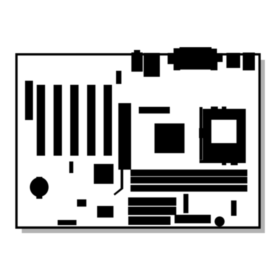
Intel Desktop Boards D815EEA2, D815EPEA2, D815EFV, and D815EPFV Product Guide Components Figure 1 shows the major components on the D815EEA2 and D815EPEA2 boards. OM11629 Item Description Item Description CNR connector (optional) Primary IDE connector Analog Devices Inc. AD1885 audio codec... -
Page 13: D815Efv And D815Epfv Desktop Board Components
Analog Devices Inc. AD1885 audio codec Primary IDE connector AGP universal connector Secondary IDE connector ATAPI-style auxiliary line in connector Intel 82801BA I/O Controller Hub (ICH2) Front panel audio connector (optional) SMSC LPC47M132 I/O controller (optional SMSC LPC47M142 I/O controller) ATAPI-style CD-ROM connector... -
Page 14: Processors
766, 733, 700, 667, 633, 600, 566, and 533A For the latest information on processor support for the boards, refer to the Intel desktop board Web site at: http://support.intel.com/support/motherboards/desktop/ For instructions on installing or upgrading the processor, see Chapter 2. -
Page 15: Main Memory
✏ NOTE ® To be fully compliant with all applicable Intel SDRAM memory specifications, the board should be populated with DIMMs that support the Serial Presence Detect (SPD) data structure. If your memory modules do not support SPD, you will see a notification to this effect on the screen at power up. -
Page 16: Chipsets
100 MHz. Chipsets The D815EEA2 and D815EFV boards include the following chipset: • Intel 82815E Graphics Memory Controller Hub (GMCH) with Accelerated Hub Architecture (AHA) bus • Intel 82801BA I/O Controller Hub (ICH2) with AHA bus •... -
Page 17: Intel ® 82815E Graphics Memory Controller Hub (Gmch)
Support for ACPI Rev 2.0 and APM Rev 1.2 compliant power management ® Intel 82801BA I/O Controller Hub (ICH2) The Intel 82801BA ICH2 has these features: • 33 MHz Peripheral Component Interface (PCI) Local Bus slots supporting PCI specification, rev 2.2: ... -
Page 18: Firmware Hub (Fwh)
Intel Desktop Boards D815EEA2, D815EPEA2, D815EFV, and D815EPFV Product Guide Firmware Hub (FWH) The 4 Mbit Firmware Hub has these features: • System BIOS • System security and management logic Input/Output (I/O) Controller The boards support either the SMSC LPC47M132 or optional SMSC LPC47M142 LPC bus I/O controller. -
Page 19: Pci Enhanced Ide Interface
Desktop Board Features ✏ NOTE Computer systems that have an unshielded cable attached to a USB port might not meet FCC Class B requirements even if no device or a low-speed USB device is attached to the cable. Use a shielded cable that meets the requirements for a full-speed USB device. -
Page 20: Audio Subsystem
The line out connector is designed to power headphones or amplified speakers only. Poor audio quality may occur if passive (non-amplified) speakers are connected to this output. Audio drivers and utilities are available from Intel’s World Wide Web site: http://support.intel.com/support/motherboards/desktop... -
Page 21: Security Passwords
(beep code) information during the Power-On Self-Test (POST). LAN Subsystem (Optional) The Intel 82562ET (in conjunction with the Intel 82801BA ICH2) provides a Fast Ethernet Wired for Management (WfM) PCI LAN subsystem providing both 10Base-T and 100Base-TX connectivity. Features include: •... -
Page 22: Lan Subsystem Software
Intel Desktop Boards D815EEA2, D815EPEA2, D815EFV, and D815EPFV Product Guide LAN Subsystem Software For Intel 82562ET Fast Ethernet WfM PCI LAN software and drivers, refer to the D815EEA2, D815EPEA2, D815EFV, or D815EPFV link on Intel’s World Wide Web site at: http://support.intel.com/support/motherboards/desktop... -
Page 23: Wake On Lan Technology (Optional)
PCI bus connectors have power, even when the computer appears to be off. If the system has a dual-colored power LED on the front panel, the sleep state is indicated by the ® LED turning amber. For more information about front panel LED states, see the Intel Desktop ®... -
Page 24: Resume On Ring
✏ NOTE 1.5 A of standby current is recommended. Refer to the Intel Desktop Board D815EEA2/D815EPEA2 Technical Product Specification or Intel Desktop Board D815EFV/D815EPFV Technical Product Specification for more information. -
Page 25: Installing And Replacing Desktop Board Components
2 Installing and Replacing Desktop Board Components This chapter tells you how to: • Install and remove memory • Install and remove the AGP card retention mechanism (included) • Install and remove AGP and GPA cards • Install the I/O shield •... -
Page 26: Installing And Removing Memory
Intel Desktop Boards D815EEA2, D815EPEA2, D815EFV, and D815EPFV Product Guide Installing and Removing Memory CAUTION Install memory in the DIMM sockets prior to installing the AGP video card to avoid interference with the memory retention mechanism. CAUTION ® To be fully compliant with all applicable Intel SDRAM memory specifications, the boards require DIMMs that support the Serial Presence Detect (SPD) data structure. -
Page 27: Removing Dimms
Installing and Replacing Desktop Board Components OM11621 Figure 4. DIMM Socket Locations (the D815EEA2 Board Is Shown) 5. Make sure the clips at either end of the DIMM socket(s) are pushed outward to the open position. 6. Holding the DIMM by the edges, remove it from its anti-static package. 7. -
Page 28: Installing And Removing The Agp Card Retention Mechanism
Intel Desktop Boards D815EEA2, D815EPEA2, D815EFV, and D815EPFV Product Guide Installing and Removing the AGP Card Retention Mechanism The AGP universal connector supports AGP (1x, 2x, and 4x) and GPA (on D815EEA2 and D815EFV boards only) cards. Newer cards have a retention notch as shown in Figure 5. The AGP card retention mechanism is not used with unnotched cards. -
Page 29: Agp Connector Location And Retention Mechanism (Rm) Placement (Inset) (The D815Eea2 Board Is Shown)
Installing and Replacing Desktop Board Components Observe the precautions in “Before You Begin” on page 25. Place the desktop board on top of an ESD safe surface, component-side up. Follow the steps outlined below to attach the RM (A) to the AGP universal connector (B): 1. -
Page 30: Removing The Agp Card Retention Mechanism
Intel Desktop Boards D815EEA2, D815EPEA2, D815EFV, and D815EPFV Product Guide Removing the AGP Card Retention Mechanism The removal instructions below are for AGP card retention mechanisms that cannot easily be snapped off the board. CAUTION Once removed using this method, the AGP RM cannot be reused. -
Page 31: Installing And Removing Agp And Gpa Cards
Installing and Replacing Desktop Board Components Installing and Removing AGP and GPA Cards Installing an AGP Card CAUTION Remove the AGP video card before installing or upgrading memory to avoid interference with the memory retention mechanism. CAUTION When installing an AGP card, press the card straight down into the AGP connector. Allowing the card to slide forward or backward even a little during installation can damage the pins of the AGP socket. -
Page 32: Installing And Removing A Gpa Card (D815Eea2 And D815Efv Only)
Intel Desktop Boards D815EEA2, D815EPEA2, D815EFV, and D815EPFV Product Guide Installing and Removing a GPA Card (D815EEA2 and D815EFV only) CAUTION Remove the GPA video card before installing or upgrading memory to avoid interference with the memory retention mechanism. CAUTION Damage can occur to the pins of the AGP universal connector if the GPA card’s edge plug is not... -
Page 33: Installing The I/O Shield
Installing and Replacing Desktop Board Components Installing the I/O Shield ✏ NOTE Systems based on this desktop board require that the I/O shield be properly installed to comply with Class B emissions requirements. The boxed desktop board comes with an I/O shield. When installed in the chassis, the shield blocks radio frequency transmissions, protects internal components from dust and foreign objects, and promotes correct airflow within the chassis. -
Page 34: Installing The Desktop Board
Intel Desktop Boards D815EEA2, D815EPEA2, D815EFV, and D815EPFV Product Guide Installing the Desktop Board Refer to your chassis manual for instructions on installing the desktop board. Seven screws for the D815EEA2 and D815EPEA2 boards and six screws for the D815EFV and D815EPFV boards secure the desktop board to the chassis. -
Page 35: Location Of The Mounting Screw Holes For The D815Efv And D815Epfv Boards
Installing and Replacing Desktop Board Components OM11626 Figure 12. Location of the Mounting Screw Holes for the D815EFV and D815EPFV Boards... -
Page 36: Installing A Processor
Intel Desktop Boards D815EEA2, D815EPEA2, D815EFV, and D815EPFV Product Guide Installing a Processor To install a processor, follow these instructions: 1. Observe the precautions in “Before You Begin” (see page 25). 2. Locate the processor socket and raise the socket handle completely (see Figure 13, B). -
Page 37: Attaching The Heatsink To The Processor
Installing and Replacing Desktop Board Components ✏ NOTE For instructions on how to install a fan heatsink for a processor 1 GHz or greater, see page 39. 5. Place the fan heatsink on top of the processor (see Figure 14). OM11619 Figure 14. -
Page 38: Removing The Processor
Intel Desktop Boards D815EEA2, D815EPEA2, D815EFV, and D815EPFV Product Guide 7. Connect the processor fan cable to the processor fan connector (see Figure 16). J1B1 J1B1 OM11156 Figure 16. Connecting the Processor Fan Cable to the Processor Fan Connector Removing the Processor To remove the processor, follow these instructions: 1. -
Page 39: Installing A 1 Ghz Processor Fan Heatsink
Installing and Replacing Desktop Board Components Installing a 1 GHz Processor Fan Heatsink To install a processor, follow the instructions given on page 36, Figure 13. Follow the instructions below to install the fan heatsink on a processor 1 GHz or greater. 1. -
Page 40: Lowering The Plastic Clip Handle
Intel Desktop Boards D815EEA2, D815EPEA2, D815EFV, and D815EPFV Product Guide 3. When properly aligned, each edge of the plastic clip should click into place. Hold the clip handle (see Figure 19, A) and very slowly lower the handle until the clip secures the fan heatsink to the processor socket. -
Page 41: Attaching The Fan To The Fan Heatsink
Installing and Replacing Desktop Board Components 4. Clip the fan (A) over the fan heatsink (B) as illustrated in Figure 20. OM11061 Figure 20. Attaching the Fan to the Fan Heatsink 5. Connect the processor fan cable to the processor fan connector (see Figure 21). J1B1 J1B1 OM11175... -
Page 42: Removing The 1 Ghz Processor Fan Heatsink
Intel Desktop Boards D815EEA2, D815EPEA2, D815EFV, and D815EPFV Product Guide Removing the 1 GHz Processor Fan Heatsink To remove the fan heatsink for the 1 GHz (or greater) processor, follow these instructions: 1. Observe the precautions in “Before You Begin” (see page 25). -
Page 43: Replacing The Battery
Installing and Replacing Desktop Board Components Replacing the Battery A coin-cell battery (CR2032) powers the real-time clock and CMOS memory. When the computer is not plugged into a wall socket, the battery has an estimated life of three years. When the computer is plugged in, the standby current from the power supply extends the life of the battery. - Page 44 Intel Desktop Boards D815EEA2, D815EPEA2, D815EFV, and D815EPFV Product Guide VARO Räjähdysvaara, jos pariston tyyppi on väärä. Paristot on kierrätettävä, jos se on mahdollista. Käytetyt paristot on hävitettävä paikallisten ympäristömääräysten mukaisesti. (Finnish) VORSICHT Bei falschem Einsetzen einer neuen Batterie besteht Explosionsgefahr. Die Batterie darf nur durch denselben oder einen entsprechenden, vom Hersteller empfohlenen Batterietyp ersetzt werden.
-
Page 45: Replacing The Battery On The D815Eea2 And D815Epea2 Boards
Installing and Replacing Desktop Board Components Replacing the Battery on the D815EEA2 and D815EPEA2 Boards To replace the battery on the D815EEA2 and D815EPEA2 boards, follow these steps: 1. Observe the precautions in “Before You Begin” (see page 25). 2. Turn off all peripheral devices connected to the computer. Always turn off the power and unplug the power cord from the computer before replacing the battery. -
Page 46: Replacing The Battery On The D815Efv And D815Epfv Boards
Intel Desktop Boards D815EEA2, D815EPEA2, D815EFV, and D815EPFV Product Guide Replacing the Battery on the D815EFV and D815EPFV Boards To replace the battery, follow these steps: 1. Observe the precautions in “Before You Begin” (see page 25). 2. Turn off all peripheral devices connected to the computer. Disconnect the computer’s power cord from the ac power source (wall outlet or power adapter). -
Page 47: Connecting The Ide Cable
Installing and Replacing Desktop Board Components Connecting the IDE Cable ® The Intel boxed desktop board package includes two IDE cables. Both are capable of connecting two drives to the desktop board. The 40-contact cable supports the Ultra DMA-33 transfer protocol. -
Page 48: Setting The Bios Configuration Jumper
Intel Desktop Boards D815EEA2, D815EPEA2, D815EFV, and D815EPFV Product Guide Setting the BIOS Configuration Jumper CAUTION Always turn off the power and unplug the power cord from the computer before changing the jumper. Moving the jumper with the power on may result in unreliable computer operation. -
Page 49: Clearing The Passwords
Installing and Replacing Desktop Board Components Clearing the Passwords This procedure assumes that the desktop board is installed in the computer and the configuration jumper block is set to normal mode. 1. Observe the precautions in “Before You Begin” (see page 25). 2. - Page 50 Intel Desktop Boards D815EEA2, D815EPEA2, D815EFV, and D815EPFV Product Guide...
-
Page 51: Updating The Bios
Updating the BIOS with the Intel ® Express BIOS Update Utility With the Intel Express BIOS Update utility you can update the system BIOS while in the † Windows environment. The BIOS file is included in an automated update utility which combines the functionality of the Intel Flash Memory Update utility and the ease-of use of Windows-based installation wizards. -
Page 52: Obtaining The Bios Update File
New BIOS files • BIOS recovery files • Intel Flash Memory Update utility You can obtain the BIOS update file through your computer supplier or from the Intel World Wide Web site: http://support.intel.com/support/motherboards/desktop/ ✏ NOTE Review the instructions distributed with the update utility before attempting a BIOS update. -
Page 53: Creating A Bios Update Media
Example: sys a: To create a bootable diskette using a non-DOS system: 1. Obtain the BIOS update file through your computer supplier or from the Intel World Wide Web site: http://support.intel.com/support/motherboards/desktop/ 2. Copy the BIOS update file to a temporary directory on your hard disk. -
Page 54: Updating The Bios
Follow the instructions provided with your CD writer to copy the extracted files from the hard disk to the CD while creating a bootable CD. 9. The CD or diskette now holds the new BIOS files, the Intel Flash Update Utility, and the recovery files. -
Page 55: Recovering The Bios
Updating the BIOS Recovering the BIOS It is unlikely that anything will interrupt the BIOS update, however, if an interruption occurs, the BIOS could be damaged. The following steps explain how to recover the BIOS if an update fails. The following procedure uses recovery mode for the Setup program. See page 48 for more information on Setup modes. - Page 56 Intel Desktop Boards D815EEA2, D815EPEA2, D815EFV, and D815EPFV Product Guide...
-
Page 57: Using The Setup Program
Service (BIS)* components available features features Setup credentials, and through the program configures chipset options extended configuration memory settings * For information about the BIS, refer to the Intel World Wide Web site at: http://developer.intel.com/design/security/index1.htm... -
Page 58: Maintenance Menu
Intel Desktop Boards D815EEA2, D815EPEA2, D815EFV, and D815EPFV Product Guide Table 9 shows the function keys available for menu screens. Table 9. BIOS Setup Program Function Keys BIOS Setup Program Function Key Description <←> or <→> Selects a different menu screen <↑>... -
Page 59: Extended Configuration Submenu
Using the Setup Program Extended Configuration Submenu To access this submenu, select Maintenance on the menu bar, then Extended Configuration. Maintenance Main Advanced Security Power Boot Exit Extended Configuration The submenu represented by Table 11 is for setting video memory cache mode. This submenu becomes available when User Defined is selected under Extended Configuration. -
Page 60: Main Menu
Intel Desktop Boards D815EEA2, D815EPEA2, D815EFV, and D815EPFV Product Guide Main Menu To access this menu, select Main on the menu bar at the top of the screen. Main Maintenance Advanced Security Power Boot Exit Table 12 describes the Main Menu. This menu reports processor and memory information and is for configuring the system date and system time. -
Page 61: Advanced Menu
Using the Setup Program Advanced Menu To access this menu, select Advanced on the menu bar at the top of the screen. Advanced Maintenance Main Security Power Boot Exit PCI Configuration Boot Configuration Peripheral Configuration IDE Configuration Diskette Configuration Event Log Configuration Video Configuration Table 13 describes the Advanced Menu. -
Page 62: Pci Configuration Submenu
Intel Desktop Boards D815EEA2, D815EPEA2, D815EFV, and D815EPFV Product Guide PCI Configuration Submenu To access this submenu, select Advanced on the menu bar, then PCI Configuration. Maintenance Main Advanced Security Power Boot Exit PCI Configuration Boot Configuration Peripheral Configuration IDE Configuration... -
Page 63: Boot Configuration Submenu
Using the Setup Program Boot Configuration Submenu To access this submenu, select Advanced on the menu bar, then Boot Configuration. Maintenance Main Advanced Security Power Boot Exit PCI Configuration Boot Configuration Peripheral Configuration IDE Configuration Diskette Configuration Event Log Configuration Video Configuration The submenu represented by Table 15 is for setting Plug and Play (PnP) options, resetting configuration data, and the power-on state of the Numlock key. -
Page 64: Peripheral Configuration Submenu
Intel Desktop Boards D815EEA2, D815EPEA2, D815EFV, and D815EPFV Product Guide Peripheral Configuration Submenu To access this submenu, select Advanced on the menu bar, then Peripheral Configuration. Maintenance Main Advanced Security Power Boot Exit PCI Configuration Boot Configuration Peripheral Configuration IDE Configuration... - Page 65 Using the Setup Program Table 16. Peripheral Configuration Submenu (continued) Feature Options Description • Disabled Parallel Port Configures the parallel port. • Enabled Auto assigns LPT1 the address 378h and the interrupt IRQ7. • Auto (default) An * (asterisk) displayed next to an address indicates a conflict with another device.
-
Page 66: Ide Configuration Submenu
Intel Desktop Boards D815EEA2, D815EPEA2, D815EFV, and D815EPFV Product Guide IDE Configuration Submenu To access this submenu, select Advanced on the menu bar, then IDE Configuration. Maintenance Main Advanced Security Power Boot Exit PCI Configuration Boot Configuration Peripheral Configuration IDE Configuration... -
Page 67: Primary/Secondary Ide Master/Slave Submenus
Using the Setup Program Primary/Secondary IDE Master/Slave Submenus To access these submenus, select Advanced on the menu bar, then IDE Configuration, and then the master or slave to be configured. Maintenance Main Advanced Security Power Boot Exit PCI Configuration Boot Configuration Peripheral Configuration IDE Configuration Primary IDE Master... -
Page 68: Diskette Configuration Submenu
Intel Desktop Boards D815EEA2, D815EPEA2, D815EFV, and D815EPFV Product Guide Table 18. Primary/Secondary IDE Master/Slave Submenus (continued) Feature Options Description • Disabled (default) Ultra DMA Specifies the Ultra DMA mode for the drive. • Mode 0 • Mode 1 • Mode 2 •... -
Page 69: Event Log Configuration Submenu
Using the Setup Program Event Log Configuration Submenu To access this menu, select Advanced on the menu bar, then Event Log Configuration. Maintenance Main Advanced Security Power Boot Exit PCI Configuration Boot Configuration Peripheral Configuration IDE Configuration Diskette Configuration Event Log Configuration Video Configuration The submenu represented by Table 20 is used to configure the event logging features. -
Page 70: Video Configuration Submenu
Intel Desktop Boards D815EEA2, D815EPEA2, D815EFV, and D815EPFV Product Guide Video Configuration Submenu To access this menu, select Advanced on the menu bar, then Video Configuration. Maintenance Main Advanced Security Power Boot Exit PCI Configuration Boot Configuration Peripheral Configuration IDE Configuration... -
Page 71: Security Menu
Using the Setup Program Security Menu To access this menu, select Security from the menu bar at the top of the screen. Maintenance Main Advanced Security Power Boot Exit The menu represented by Table 22 is for setting passwords and security features. Table 22. -
Page 72: Power Menu
Intel Desktop Boards D815EEA2, D815EPEA2, D815EFV, and D815EPFV Product Guide Power Menu To access this menu, select Power from the menu bar at the top of the screen. Maintenance Main Advanced Security Power Boot Exit ACPI The menu represented in Table 23 is for setting the power management features. -
Page 73: Apm Submenu
Using the Setup Program APM Submenu To access this menu, select Power on the menu bar, then APM. Maintenance Main Advanced Security Power Boot Exit ACPI The submenu represented in Table 24 is for setting the APM features. Table 24. APM Submenu Feature Options... -
Page 74: Boot Menu
Intel Desktop Boards D815EEA2, D815EPEA2, D815EFV, and D815EPFV Product Guide Boot Menu To access this menu, select Boot from the menu bar at the top of the screen. Maintenance Main Advanced Security Power Boot Exit The menu represented in Table 26 is used to set the boot features and the boot sequence. -
Page 75: Boot Device Priority Submenu
After the predefined boot device types (removable devices, hard drives, and ATAPI CD-ROM drives), the entries in this list will reflect as many boot entry vector (BEV) boot devices (for example, Intel UNDI, PXE devices) and SCSI CD-ROM drives as are installed, up to the five BEV boot devices supported by the BIOS. -
Page 76: Hard Disk Drives Submenu
Intel Desktop Boards D815EEA2, D815EPEA2, D815EFV, and D815EPFV Product Guide Hard Disk Drives Submenu To access this menu, select Boot from the menu bar, then Hard Disk Drives. Maintenance Main Advanced Security Power Boot Exit Boot Device Priority Hard Disk Drives... -
Page 77: Atapi Cdrom Drives
Using the Setup Program ATAPI CDROM Drives To access this menu, select Boot from the menu bar, then ATAPI CDROM Drives. Maintenance Main Advanced Security Power Boot Exit Boot Device Priority Hard Disk Drives Removeable Devices ATAPI CDROM Drives The submenu represented in Table 30 is for setting ATAPI CD-ROM drives. Table 30. - Page 78 Intel Desktop Boards D815EEA2, D815EPEA2, D815EFV, and D815EPFV Product Guide...
-
Page 79: Technical Reference
5 Technical Reference Desktop Board Connectors CAUTION Many of the midboard and front panel connectors provide operating voltage (+5 V dc and +12 V dc, for example) to devices inside the computer chassis, such as fans and internal peripherals. These connectors are not overcurrent protected. Do not use these connectors for powering devices external to the computer chassis. -
Page 80: Back Panel Connectors
Intel Desktop Boards D815EEA2, D815EPEA2, D815EFV, and D815EPFV Product Guide Back Panel Connectors Figure 28 shows the back panel connectors on the desktop board. The back panel connectors are color-coded in compliance with PC 99 recommendations. The figure legend below lists the colors used. -
Page 81: Midboard Connectors
Technical Reference Midboard Connectors Audio Connectors Figure 29 shows the location of the audio connectors. OM11638 Item Description ATAPI-style auxiliary line in Front panel audio (optional) ATAPI-style CD-ROM Figure 29. Audio Connectors (the D815EEA2 Board Is Shown) -
Page 82: Power And Hardware Control Connectors (The D815Eea2 Board Is Shown)
Intel Desktop Boards D815EEA2, D815EPEA2, D815EFV, and D815EPFV Product Guide Power and Hardware Control Connectors Figure 30 shows the power and hardware connectors. OM11631 Item Description Processor fan (fan 1) Power Chassis fan (fan 3) Front panel USB (optional) SCSI LED... -
Page 83: Add-In Board And Peripheral Interface Connectors For The D815Eea2 And D815Epea2 Boards
Technical Reference Add-In Board and Peripheral Interface Connectors for the D815EEA2 and D815EPEA2 Boards Figure 31 shows the add-in board and peripheral interface connectors. OM11641 Item Description Item Description CNR (optional) PCI slot 5 DVO (D815EEA2U only) PCI slot 4 Diskette drive PCI slot 3 Primary IDE... -
Page 84: Add-In Board And Peripheral Interface Connectors For The D815Efv And D815Epfv Boards
Intel Desktop Boards D815EEA2, D815EPEA2, D815EFV, and D815EPFV Product Guide Add-In Board and Peripheral Interface Connectors for the D815EFV and D815EPFV Boards Figure 32 shows the add-in board and peripheral interface connectors. OM11640 Item Description Item Description CNR (optional) DVO (D815EFV only) -
Page 85: Front Panel Connectors
Technical Reference Front Panel Connectors Figure 33 shows the location of the front panel connectors. J9H2 J9H3 OM11618 Item Description Item Description Alternate front panel power On/Off switch LED connector Reserved No connect Reset switch Ground Hard drive activity LED +5 V Power LED Figure 33. -
Page 86: Desktop Board Resources
Intel Desktop Boards D815EEA2, D815EPEA2, D815EFV, and D815EPFV Product Guide Desktop Board Resources Interrupts Table 32. Interrupts System Resource I/O channel check Reserved, interval timer Reserved, keyboard buffer full Reserved, cascade interrupt from slave PIC COM2* (user available if COM2 is not present) -
Page 87: A Error Messages And Indicators Bios Beep Codes
4Á 8ƒƒ€ƒÁFp„„frp„ÁfyiÁByithf…€ƒ„Á The board reports POST errors in two ways: By sounding a beep code By displaying an error message on the monitor The BIOS beep codes are listed in Table 33. The BIOS also issues a beep code (one long tone followed by two short tones) during POST if the video configuration fails (a faulty video card or no card installed) or if an external ROM module does not properly checksum to zero. -
Page 88: Bios Error Messages
Intel Desktop Boards D815EEA2, D815EPEA2, D815EFV, and D815EPFV Product Guide BIOS Error Messages When a recoverable error occurs during the POST, the BIOS displays an error message describing the problem (see Table 34). Table 34. BIOS Error Messages Error Message... - Page 89 Error Messages and Indicators Table 34. BIOS Error Messages (continued) Error Message Explanation Memory Size Decreased Memory size has decreased since the last boot. If no memory was removed, then memory may be bad. Memory Size Increased Memory size has increased since the last boot. If no memory was added, there may be a problem with the system.
- Page 90 Intel Desktop Boards D815EEA2, D815EPEA2, D815EFV, and D815EPFV Product Guide...
-
Page 91: B Regulatory Compliance
B Regulatory Compliance This appendix contains: • Safety standards, electromagnetic compatibility (EMC) regulations, and product certification markings for this desktop board • Instructions and precautions for integrators who are installing this desktop board in a chassis Safety Regulations This desktop board complies with the safety regulations stated in Table 35 when correctly installed in a compatible host system. -
Page 92: Product Certification Markings
The desktop boards have the following product certification markings: • UL joint US/Canada Recognized Component mark: consists of small c followed by a stylized backward UR and followed by a small US. Includes adjacent UL file number for Intel desktop boards: E210882 (component side). •... -
Page 93: Installation Precautions
Regulatory Compliance Installation Precautions When you install and test the desktop board, observe all warnings and cautions in the installation instructions. To avoid injury, be careful of: • Sharp pins on connectors • Sharp pins on printed circuit assemblies • Rough edges and sharp corners on the chassis •... -
Page 94: Chassis And Component Certifications
Intel Desktop Boards D815EEA2, D815EPEA2, D815EFV, and D815EPFV Product Guide Chassis and Component Certifications Ensure that the chassis and certain components; such as the power supply, peripheral drives, wiring, and cables; are components certified for the country or market where used. Agency certification marks on the product are proof of certification. -
Page 95: Use Only For Intended Applications
Regulatory Compliance Use Only for Intended Applications All Intel desktop processor boards are evaluated as Information Technology Equipment (I.T.E.) for use in personal computers for installation in homes, offices, schools, computer rooms, and similar locations. The suitability of this product for other applications or environments, such as medical,... - Page 96 Intel Desktop Boards D815EEA2, D815EPEA2, D815EFV, and D815EPFV Product Guide...