Sign In
Upload
Manuals
Brands
YOKOGAWA Manuals
Transmitter
DpharpEJX vigilantplant EJX Series
YOKOGAWA DpharpEJX vigilantplant EJX Series Manuals
Manuals and User Guides for YOKOGAWA DpharpEJX vigilantplant EJX Series. We have
3
YOKOGAWA DpharpEJX vigilantplant EJX Series manuals available for free PDF download: User Manual, Manual
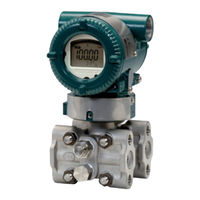
YOKOGAWA DpharpEJX vigilantplant EJX Series User Manual (131 pages)
Fieldbus Communication Type
Brand:
YOKOGAWA
| Category:
Transmitter
| Size: 1 MB
Table of Contents
Table of Contents
2
1 Introduction
7
Regarding this Manual
7
Safe Use of this Product
8
Warranty
9
ATEX Documentation
9
2 Handling Cautions
11
Installation of an Explosion-Protected Instrument
11
FM Approval
11
CSA Certification
13
CENELEC ATEX Certification
14
3 About Fieldbus
18
Outline
18
Internal Structure of EJX
18
System/Network Management VFD
18
Function Block VFD
18
Logical Structure of each Block
18
Wiring System Configuration
18
4 Getting Started
19
Connection of Devices
19
Host Setting
20
Bus Power on
21
Integration of DD
21
Reading the Parameters
21
Continuous Record of Values
22
Generation of Alarm
22
5 Configuration
23
Network Design
23
Network Definition
23
Definition of Combining Function Blocks
24
Setting of Tags and Addresses
25
Communication Setting
26
VCR Setting
26
Function Block Execution Control
27
Block Setting
27
Link Object
27
Trend Object
28
View Object
28
Function Block Parameters
32
6 Explanation of Basic Items
33
Outline
33
Setting and Changing Parameters for the Whole Process
33
SENSOR Transducer Block
33
Functional Block
33
Block Mode
33
Functions Relating to Pressure/Differential Pressure
34
Functions Relating to Static Pressure
35
Functions Relating to Capsule and Amplifier Temperature
36
Block_Err
36
Xd_Error
36
LCD Transducer Block
37
Outline of the Functions
37
Block Mode
37
Display Contents of the Integral Indicator
37
Example Displays of the Integral Indicator
38
Procedure to Set the Built-In Display
39
Units that Can be Displayed on the LCD by the Automatic Link Function
41
AI Function Block
42
Function Blocks
42
Block Mode
42
Io_Opts
42
Status_Opt
42
Out_D
43
Basic Parameters of the AI Block
43
7 In-Process Operation
44
Mode Transition
44
Generation of Alarm
44
Indication of Alarm
44
Alarms and Events
44
Simulation Function
45
8 Device Information
46
Device Status
46
Status of each Parameter in Failure Mode
49
9 Parameter Lists
51
Resource Block
51
SENSOR Transducer Block
53
LCD Transducer Block
57
Al Function Block
59
10 General Specifications
61
Standard Specifications
61
OPTIONAL SPECIFICATIONS (for Explosion Protected Type)
61
Appendix 1. Signal Characterizer (SC) Block
64
A1.1 Schematic Diagram of Signal Characterizer Block
64
Input/Output Parameters
64
A1.2 Input Section
66
A1.2.1 Determining the Mode
66
A1.2.2 Judging BLOCK_ERR
66
A1.3 Line-Segment Factor Determination Section
67
A1.3.1 Conditions for Configuring Valid Coefficients
67
A1.4 List of Signal Characterizer Block Parameters
69
A1.5 Application Example
70
A1.5.1 Input Compensation
70
A1.5.2 Calorie Flow Compensation
70
A1.5.3 Backward Control
70
Appendix 2. Integrator (IT) Block
72
A2.1 Schematic Diagram of Integrator Block
72
A2.2 Input Process Section
73
A2.2.1 Determining Input Value Statuses
73
A2.2.2 Converting the Rate
73
A2.2.3 Converting Accumulation
74
A2.2.4 Determining the Input Flow Direction
74
A2.3 Adder
75
A2.3.1 Status of Value after Addition
75
A2.3.2 Addition
75
A2.4 Integrator
76
A2.5 Output Process
77
A2.5.1 Status Determination
77
A2.5.2 Determining the Output Value
78
A2.5.3 Mode Handling
79
A2.6 Reset
80
A2.6.1 Reset Trigger
80
A2.6.2 Reset Timing
80
A2.6.3 Reset Process
81
A2.7 List of Integrator Block Parameters
82
Appendix 3. Input Selector (IS) Block
84
A3.1 Input Selector Function Block Schematic
84
A3.2 Input Section
86
A3.2.1 Mode Handling
86
A3.2.2 MIN_GOOD Handling
86
A3.3 Selection
87
A3.3.1 OP_SELECT Handling
87
A3.3.2 SELECTION Handling
88
A3.4 Output Processing
94
A3.4.1 Handling of SELECTED
94
A3.4.2 out Processing
95
A3.4.3 Status_Opts
96
A3.5 List of Input Selector Block Parameters
96
A3.6 Application Example
97
Appendix 4. Arithmetic (AR) Block
98
A4.1 Arithmetic Function Block Schematic
98
A4.2 Input Section
99
A4.2.1 Main Inputs
99
A4.2.2 Auxiliary Inputs
99
A4.2.3 Input_Opts
100
A4.2.4 Relationship between the Main Inputs and PV
100
A4.3 Computation Section
101
A4.3.1 Computing Equations
101
A4.3.2 Compensated Values
101
A4.3.3 Average Calculation
101
A4.4 Output Section
101
A4.4.1 Mode Handling
102
A4.4.2 Status Handling
102
A4.5 List of the Arithmetic Block Parameters
103
Appendix 5. Pid Block
105
A5.1 Function Diagram
105
A5.2 Functions of PID Block
105
Algorithm
105
A5.7 Control Action Bypass
105
A5.10 Bumpless Transfer
105
A5.11 Setpoint Limiters
105
A5.12 External-Output Tracking
105
A5.13 Measured-Value Tracking
105
A5.17 Mode Shedding Upon Computer Failure
105
A5.4.1 PV-Proportional and -Derivative Type PID (I-PD) Control Algorithm
108
A5.17.1 Shed_Opt
112
A5.18 Alarms
112
A5.18.1 Block Alarm (BLOCK_ALM)
112
A5.18.2 Process Alarms
112
A5.19 Example of Block Connections
113
A5.20 View Object for PID Function Block
113
Appendix 6. Link Master Functions
115
A6.1 Link Active Scheduler
115
A6.2 Link Master
115
A6.3 Transfer of las
116
A6.4 LM Functions
117
A6.5 LM Parameters
118
A6.5.1 LM Parameter List
118
A6.5.2 Descriptions for LM Parameters
120
A6.6 Faqs
122
Appendix 7. Software Download
123
A7.1 Benefits of Software Download
123
A7.2 Specifications
123
A7.3 Preparations for Software Downloading
123
A7.4 Software Download Sequence
124
A7.5 Download Files
124
A7.6 Steps after Activating a Field Device
125
A7.7 Troubleshooting
126
A7.8 Resource Block's Parameters Relating to Software Download
126
A7.9 System/Network Management VFD Parameters Relating to Software Download
128
A7.10 Comments on System/Network Management VFD Parameters
129
Relating to Software Download
129
Revision Record
131
Advertisement
YOKOGAWA DpharpEJX vigilantplant EJX Series Manual (45 pages)
HART Communication Type
Brand:
YOKOGAWA
| Category:
Transmitter
| Size: 1 MB
Table of Contents
Table of Contents
2
1 Introduction
4
Regarding this Manual
4
Safe Use of this Product
5
Warranty
5
ATEX Documentation
6
Matching of Communicator DD and Instrument DD
7
2 Conditions of Communication Line
8
Interconnection between Dpharp and the HART Communicator
8
Communication Line Requirements
8
Power Supply Voltage and Load Resistance
8
3 Operation
9
Basic Operation of the 275 HART Communicator
9
Keys and Functions
9
Display
10
Calling up Menu Addresses
10
Entering, Setting, and Sending Data
11
Parameter Usage and Selection
12
Menu Tree
13
Basic Setup
14
Tag and Device Information
14
Unit
14
Range Change
15
Keypad Input
15
Apply Values
16
Output Mode
17
Damping Time Constant Setup
17
Output Signal Low Cut Mode Setup
18
Impulse Line Connection Orientation Setup
18
Detailed Setup
19
Bi-Directional Flow Measurement
19
Integral Indicator Display Mode
19
Integral Indicator Scale Setup
20
Unit for Displayed Temperature
22
Unit for Displayed Static Pressure
22
Test Output
23
Sensor Trim
24
Zero Trim
24
Auto Sensor Trim
25
Full Sensor Trim
25
Manual Sensor Trim
25
Reset Trim Adjustment to Factory Setting
26
Sensor Trim for Static Pressure
26
Trim Analog Output
26
Burst Mode
28
Multidrop Mode
29
External Switch Mode
30
CPU Failure Burnout Direction and Hardware Write Protect
30
Software Write Protect
31
Entering Password to Enable the Parameter Changes
31
Releasing Password
31
Setting Password
31
Software Seal
32
Signal Characterizer
32
Process Alarm
33
Status Output (Option Code AL)
34
Capillary Fill Fluid Density Compensation
35
4 Self-Diagnostics
37
Identify Problems by Using the Communicator
37
Checking with Integral Indicator
37
Alarm Message Summary
38
Alarms and Countermeasures
38
5 Parameter Summary
40
Appendix 1. Safety Instrumented Systems Installation
42
Revision Record
45
YOKOGAWA DpharpEJX vigilantplant EJX Series User Manual (38 pages)
BRAIN Communication Type
Brand:
YOKOGAWA
| Category:
Transmitter
| Size: 1 MB
Table of Contents
Table of Contents
2
1 Introduction
4
Regarding this Manual
4
Safe Use of this Product
5
Warranty
5
ATEX Documentation
6
2 Conditions of Communication Line
7
Connecting the BT200
7
Communication Line Requirements
7
Power Supply Voltage and Load Resistance
7
3 Operation
8
BT200 Operating Procedures
8
Key Layout and Screen Display
8
Operating Key Functions
9
Alphanumeric Keys and Shift Keys
9
Function Keys
9
Calling up Menu Addresses Using the Operating Keys
10
Printout (for BT200 Printer Option)
10
Setting Parameters Using the BT200
11
Parameter Usage and Selection
11
Menu Tree
12
Setting Parameters
13
Tag No. Setup
13
Calibration Range Setup
13
Damping Time Constant Setup
14
Output Mode and Integral Indicator Display Mode Setup
15
Output Signal Low Cut Mode Setup
15
Integral Indicator Scale Setup
16
Unit Setup for Displayed Temperature
17
Operation Mode Setup
17
Impulse Line Connection Orientation Setup
18
CPU Failure Burnout Direction and Hardware Write Protect
18
Software Write Protect
18
Output Status Setup When a Hardware Error Occurs
19
Bi-Directional Flow Measurement Setup
19
Range Change While Applying Actual Inputs
20
Sensor Trim
21
Test Output Setup
24
Signal Characterizer
24
Process Alarm
25
Status Output (Option Code AL)
25
Capillary Fill Fluid Density Compensation
26
Adjustment Information and User Memo Fields
27
Displaying Data Using the BT200
27
Displaying Measured Data
27
Display Transmitter Model and Specifications
27
Parameter Summary
27
4 Self-Diagnostics
28
Checking for Problems
28
Identifying Problems with BT200
28
Checking with Integral Indicator
29
Alarms and Countermeasures
30
5 Parameter Summary
31
Appendix 1. Safety Instrumented Systems Installation
35
Advertisement
Advertisement
Related Products
YOKOGAWA Dpharp EJX310A
YOKOGAWA Dpharp EJX430A
YOKOGAWA Dpharp EJX510A
YOKOGAWA Dpharp EJX530A
YOKOGAWA Dpharp EJX910A
YOKOGAWA DPharp EJX***A Series
YOKOGAWA DP harp EJX110A
YOKOGAWA DP harp EJX130A
YOKOGAWA DP harp EJX310A
YOKOGAWA DP harp EJX440A
YOKOGAWA Categories
Measuring Instruments
Test Equipment
Transmitter
Controller
Media Converter
More YOKOGAWA Manuals
Login
Sign In
OR
Sign in with Facebook
Sign in with Google
Upload manual
Upload from disk
Upload from URL