Sign In
Upload
Manuals
Brands
YASKAWA Manuals
Controller
L1000A Series
YASKAWA L1000A Series Manuals
Manuals and User Guides for YASKAWA L1000A Series. We have
9
YASKAWA L1000A Series manuals available for free PDF download: Technical Manual, Quick Start Manual, Installation Manual
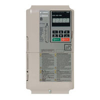
YASKAWA L1000A Series Technical Manual (522 pages)
200 V Class: 1.5 to 110 kW (2 to 150 HP) 400 V Class: 1.5 to 315 kW (2 to 500 HP) 600 V Class: 1.5 to 160 kW (2 to 250 HP)
Brand:
YASKAWA
| Category:
Controller
| Size: 61.2 MB
Table of Contents
Table of Contents
5
Quick Reference
3
Table of Contents
5
YASKAWA ELECTRIC SIEP C710616 38F YASKAWA AC Drive - L1000A Technical Manual
13
I.1 Preface
14
Trademarks
15
I.2 General Safety
16
Safety Messages
17
General Application Precautions
20
Motor Application Precautions
22
Drive Label Warnings
23
Receiving
25
Section Safety
26
General Description
27
Control Mode Selection
28
Model Number and Nameplate Check
29
Model Number
30
Component Names
31
IP00 Enclosure
34
Front Views
38
2 Mechanical Installation
39
Section Safety
40
Mechanical Installation
42
Installation Orientation and Spacing
43
Instructions on Installation
44
Top Protective Cover
45
Digital Operator Remote Usage
46
Exterior and Mounting Dimensions
49
Electrical Installation
53
Section Safety
54
Standard Connection Diagram
58
Main Circuit Connection Diagram
61
Terminal Block Configuration
62
Terminal Cover
63
Digital Operator and
65
Main Circuit Wiring
68
Protecting Main Circuit Terminals
69
Main Circuit Terminal and Motor Wiring
76
Control Circuit Wiring
78
Terminal Configuration
80
Wiring the Control Circuit Terminal
81
Switches and Jumpers on the Terminal Board
83
Control I/O Configuration
84
Sinking/Sourcing Mode Selection for Safe Disable Inputs
85
Connect to a Pc
86
Memobus/Modbus Termination
87
Wiring Checklist
88
Start-Up Programming & Operation
89
Section Safety
90
Using the Digital Operator
93
LCD Display
94
The Drive and Operation Status Display
95
LO/RE LED and RUN LED Indications
96
Menu Structure for Digital Operator
97
The Drive and Programming Modes
98
Changing Parameter Settings or Values
100
Verifying Parameter Changes: Verify Menu
101
Simplified Setup Using the Setup Group
102
Switching between LOCAL and REMOTE
103
Start-Up Flowcharts
104
Flowchart A: Installation, Wiring, Basic Setup for Motor and Elevator
105
Power on
106
Motor Rotation Direction Setup
107
Digital Operator Display Unit Selection
108
Flowchart B: Auto-Tuning for Induction Motors
109
Flowchart C: Auto-Tuning for PM Motors
110
Flowchart D: PG Encoder Offset Auto-Tuning
111
Auto-Tuning
112
Before Auto-Tuning the Drive
115
Auto-Tuning Interruption and Fault Codes
116
Parameter Settings During Induction Motor Auto-Tuning: T1
118
Parameter Settings During PM Motor Auto-Tuning: T2
120
Setup Procedure for Elevator Applications
123
Speed Selection Using Digital Inputs (B1-01 = 0)
124
Multi-Function Terminal Setup
126
Accel/Decel Ramp and Jerk Settings
127
Inspection Operation
128
Brake Sequence
129
Adjustments for Elevator Ride Comfort
133
Rescue Operation
134
Setup Troubleshooting and Possible Solutions
152
Motor Is too Hot
153
Ground Fault Circuit Interrupter (ELCB/GFCI) Trips During Run
154
Verifying Parameter Settings and Backing up Changes
156
Copy Function
157
Parameter Details
159
A: Initialization
160
A2: User Parameters
165
B: Application
166
B2: Magnetic Flux Compensation
169
B6: Dwell Function
170
B8: Energy Saving
171
C: Tuning
172
C2: Jerk Settings
174
C3: Slip Compensation
175
C4: Torque Compensation
177
C5: Speed Control Loop
179
C6: Carrier Frequency
182
D: Reference Settings
183
D6: Field Forcing
186
E: Motor Parameters
187
E2: Motor Parameters
188
E3: V/F Pattern for Motor 2
191
E4: Motor 2 Parameters
192
E5: PM Motor Settings
193
F: Option Settings
195
F3: Digital Input Card Settings
198
F4: Analog Monitor Card Settings
199
F5: Digital Output Card Settings
200
F6: Communication Option Card
201
Canopen Parameters
202
H: Terminal Functions
203
H2: Multi-Function Digital Outputs
208
H3: Multi-Function Analog Inputs
217
H4: Multi-Function Analog Outputs
220
H5: Memobus/Modbus Serial Communication
222
L: Protection Functions
223
L2: Undervoltage Detection
227
L4: Speed Detection
229
L5: Automatic Fault Reset
231
L6: Torque Detection
232
L7: Torque Limit
234
L8: Drive Protection
235
N: Special Adjustments
242
N5: Inertia Compensation
243
N6: Online Tuning
246
N9: Current Detection Adjustments
248
O: Operator Related Settings
249
O2: Digital Operator Keypad Functions
252
O3: Copy Function
254
O4: Maintenance Monitor Settings
255
S: Elevator Parameters
258
S2: Slip Compensation for Elevators
260
S3: Start/Stop Optimization
261
S4: Rescue Operation
264
S5: Short Floor Operation
267
S6: Faults for Elevator Applications
273
T: Motor Tuning
274
U: Monitor Parameters
275
U1: Operation Status Monitors
275
Troubleshooting
277
Section Safety
278
Drive Alarms, Faults, and Errors
280
Alarm and Error Displays
281
Fault Detection
286
Alarm Detection
299
Operator Programming Errors
305
Auto-Tuning Fault Detection
307
Copy Function Related Displays
311
Diagnosing and Resetting Faults
314
Fault Reset Methods
315
Periodic Inspection & Maintenance
317
Section Safety
318
Inspection
321
Recommended Periodic Inspection
322
Periodic Maintenance
323
Drive Cooling Fans and Circulation Fans
325
Cooling Fan Component Names
326
And 50004 to 50027
327
And 50041
329
Cooling Fan Replacement: CIMR-LU40075 and 40091
331
And 50052 to 50200
334
Cooling Fan Replacement: CIMR-LU40370
338
Cooling Fan Replacement: CIMR-LU40450 and 40605
340
Drive Replacement
345
Replacing the Drive
346
Peripheral Devices & Options
349
Section Safety
350
Drive Options and Peripheral Devices
353
Connecting Peripheral Devices
355
Option Card Installation
356
Installing the Option
357
Installing Peripheral Devices
367
Installing a Molded Case Circuit Breaker (MCCB)
369
Installing a Magnetic Contactor at the Power Supply Side
370
Connecting an AC Reactor or a DC Link Choke
371
Connecting a Surge Absorber
372
Fuse/Fuse Holder
374
Attachment for External Heatsink Mounting
375
Installing a Motor Thermal Overload (Ol) Relay on the Drive Output
376
Appendix: a
377
A. Specifications
377
Three-Phase 200 V Class Drives
378
Three-Phase 400 V Class Drives
379
Three-Phase 600 V Class Drives
380
Drive Specifications
381
A.4 Drive Specifications
381
Drive Watt Loss Data
383
Drive Derating Data
385
Carrier Frequency Derating
386
Temperature Derating
389
Appendix: B
391
B. Parameter List
391
This Appendix Contains a Full Listing of All Parameters and Settings Available in the Drive.
392
Understanding the Parameter Table
392
Parameter Groups
393
B.2 Parameter Groups
393
B.3 Parameter Table
394
B: Application
395
C: Tuning
396
D: Speed References
400
E: Motor Parameters
402
F: Option Settings
405
H: Multi-Function Terminals
408
L: Protection Functions
415
N: Advanced Performance Set-Up
419
O: Operator Related Parameters
421
S: Elevator Parameters
424
T: Motor Tuning
428
U: Monitors
430
Parameter Table
394
Control Mode Dependent Parameter Default Values
437
Defaults by Drive Model Selection (O2-04)
438
Defaults and Setting Ranges by Display Unit Selection (O1-03)
442
C. Memobus/Modbus Communications
443
C.1 Memobus/Modbus Configuration
444
C.2 Communication Specifications
445
C.3 Connecting to a Network
446
Network Termination
447
C.4 Memobus/Modbus Setup Parameters
448
C.5 Drive Operations by Memobus/Modbus
451
C.6 Communications Timing
452
C.7 Message Format
453
Error Check
454
C.8 Message Examples
455
Writing to Multiple Registers
456
C.9 Memobus/Modbus Data Table
457
Monitor Data
458
Broadcast Messages
465
Fault Trace Contents
466
Alarm Register Contents
467
C.10 Enter Command
468
C.11 Communication Errors
469
C.12 Self-Diagnostics
470
D. Standards Compliance
471
D.1 Section Safety
472
D.2 European Standards
474
EMC Guidelines Compliance
477
D.3 UL and CSA Standards
481
Installing Input Fuses
488
CSA Standards Compliance
490
D.4 Safe Disable Input Function
493
Precautions
494
Using the Safe Disable Function
495
D.5 EN81-1/20 Conform Circuit with One Motor Contactor
498
D.6 EN81-20 Conform Circuit with no Motor Contactor
499
E. Quick Reference Sheet
501
E.1 Drive and Motor Specifications
502
E.2 Multi-Function I/O Terminal Settings Record
504
E.3 User Setting Table
505
Index
509
Revision History
521
Advertisement
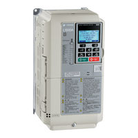
YASKAWA L1000A Series Technical Manual (452 pages)
AC Drive for Elevator Applications; Type: CIMR-LUxA; 200 V Class: 3.7 to 110 kW (5 to 150 HP); 400 V Class: 3.7 to 132 kW (5 to 200 HP) A
Brand:
YASKAWA
| Category:
Controller
| Size: 58.78 MB
Table of Contents
Table of Contents
5
Quick Reference
3
Table of Contents
5
YASKAWA ELECTRIC SIEP C710616 38A YASKAWA AC Drive L1000A Technical Manual
13
I.1 Preface
14
Trademarks
15
I.2 General Safety
16
Safety Messages
17
General Application Precautions
20
Motor Application Precautions
22
Drive Label Warnings
23
Warranty Information
24
1 Receiving
25
Section Safety
26
General Description
27
Control Mode Selection
28
Model Number and Nameplate Check
29
Component Names
31
IP00 Enclosure
34
Front Views
35
Mechanical Installation
37
Section Safety
38
2 Mechanical Installation
39
Top Protective Cover
40
Digital Operator Remote Usage
41
Exterior and Mounting Dimensions
44
3 Electrical Installation
47
Section Safety
48
Standard Connection Diagram
52
Main Circuit Connection Diagram
55
Terminal Block Configuration
56
Terminal Cover
57
Digital Operator and
59
Main Circuit Wiring
62
Main Circuit Terminal and Motor Wiring
66
Control Circuit Wiring
69
Terminal Configuration
71
Wiring the Control Circuit Terminal
72
Switches and Jumpers on the Terminal Board
74
Control I/O Configuration
75
Sinking/Sourcing Mode Selection for Safe Disable Inputs
76
Connect to a Pc
77
Memobus/Modbus Termination
78
Wiring Checklist
79
4 Start-Up Programming & Operation
81
Section Safety
82
Using the Digital Operator
85
LCD Display
86
Powering up the Drive and Operation Status Display
87
LO/RE LED and RUN LED Indications
88
Menu Structure for Digital Operator
89
The Drive and Programming Modes
90
Changing Parameter Settings or Values
92
Verifying Parameter Changes: Verify Menu
93
Simplified Setup Using the Setup Group
94
Switching between LOCAL and REMOTE
95
Start-Up Flowcharts
96
Flowchart A: Installation, Wiring, Basic Setup for Motor and Elevator
97
Power on
98
Motor Rotation Direction Setup
99
Flowchart B: Auto-Tuning for Induction Motors
101
Flowchart C: Auto-Tuning for PM Motors
102
Flowchart D: PG Encoder Offset Auto-Tuning
103
Auto-Tuning
104
Before Auto-Tuning the Drive
106
Auto-Tuning Interruption and Fault Codes
107
Auto-Tuning Operation Example
108
Parameter Settings During Induction Motor Auto-Tuning: T1
110
Parameter Settings During PM Motor Auto-Tuning: T2
112
Setup Procedure for Elevator Applications
114
Speed Selection Using Digital Inputs (B1-01 = 0)
115
Multi-Function Terminal Setup
117
Inspection Operation
118
Brake Sequence
119
Adjustments for Elevator Ride Comfort
122
Rescue Operation
123
Setup Troubleshooting and Possible Solutions
135
Motor Is too Hot
136
Riding Comfort Related Problems
137
Verifying Parameter Settings and Backing up Changes
139
Password Settings: A1-04, A1-05
140
5 Parameter Details
141
A: Initialization
142
A2: User Parameters
147
B: Application
148
B2: Magnetic Flux Compensation
150
B4: Delay Timers
151
B7: Droop Control (CLV/PM)
152
B8: Energy Saving
153
C: Tuning
154
C2: Jerk Settings
156
C3: Slip Compensation
157
C4: Torque Compensation
159
C5: Speed Control Loop
161
C6: Carrier Frequency
163
D: Reference Settings
165
D6: Field Forcing
168
E: Motor Parameters
169
E2: Motor Parameters
170
E3: V/F Pattern for Motor 2
173
E4: Motor 2 Parameters
174
E5: PM Motor Settings
175
F: Option Settings
177
F3: Digital Input Card Settings
180
F5: Digital Output Card Settings
181
F6: Communication Option Card
182
Canopen Parameters
183
H: Terminal Functions
184
H2: Multi-Function Digital Outputs
188
H3: Multi-Function Analog Inputs
197
H4: Multi-Function Analog Outputs
200
H5: Memobus/Modbus Serial Communication
201
L: Protection Functions
202
L2: Undervoltage Detection
204
L4: Speed Detection
206
L5: Automatic Fault Reset
207
L6: Torque Detection
209
L7: Torque Limit
211
N: Special Adjustments
217
N6: Online Tuning
220
N8: PM Motor Control Tuning
221
N9: Current Detection Adjustments
223
O: Operator Related Settings
224
O2: Digital Operator Keypad Functions
226
O3: Copy Function
228
S: Elevator Parameters
231
S2: Slip Compensation for Elevators
232
S3: Start/Stop Optimization
233
S4: Rescue Operation
237
S5: Short Floor Operation
239
S6: Faults for Elevator Applications
245
T: Motor Tuning
246
U: Monitor Parameters
247
6 Troubleshooting
249
Section Safety
250
Drive Alarms, Faults, and Errors
252
Alarm and Error Displays
253
Fault Detection
257
Alarm Detection
269
Operator Programming Errors
274
Auto-Tuning Fault Detection
276
Copy Function Related Displays
280
Diagnosing and Resetting Faults
283
Fault Reset Methods
284
7 Periodic Inspection & Maintenance
285
Section Safety
286
Inspection
289
Recommended Periodic Inspection
290
Periodic Maintenance
291
Drive Cooling Fans and Circulation Fans
293
Cooling Fan Component Names
294
Cooling Fan Replacement: 2A0018 to 2A0075 and 4A0009 to 4A0039
295
Cooling Fan Replacement: 2A0085, 2A0115, 4A0045, and 4A0060
297
Cooling Fan Replacement: 4A0075, 4A0091
299
Cooling Fan Replacement: 2A0145 to 2A0415, 4A0112 to 4A0260
301
Drive Replacement
305
Replacing the Drive
306
8 Peripheral Devices & Options
309
Section Safety
310
Drive Options and Peripheral Devices
313
Connecting Peripheral Devices
315
Option Card Installation
316
Installing Peripheral Devices
318
Installing a Molded Case Circuit Breaker (MCCB)
320
Connecting an AC Reactor or a DC Link Choke
321
Connecting a Surge Absorber
322
Fuse/Fuse Holder
324
Attachment for External Heatsink Mounting
325
Appendix: a
327
A. Specifications
327
Three-Phase 200 V Class Drives
328
Three-Phase 400 V Class Drives
329
A.3 Drive Specifications
330
Drive Specifications
330
Drive Watt Loss Data
331
Drive Derating Data
332
Temperature Derating
333
Appendix: B
335
B. Parameter List
335
This Appendix Contains a Full Listing of All Parameters and Settings Available in the Drive.
336
Understanding the Parameter Table
336
Parameter Groups
337
B.2 Parameter Groups
337
Parameter Table
338
B.3 Parameter Table
338
B: Application
339
C: Tuning
340
D: Speed References
344
E: Motor Parameters
345
F: Option Settings
348
H: Multi-Function Terminals
352
L: Protection Functions
358
N: Advanced Performance Set-Up
362
O: Operator Related Parameters
364
S: Elevator Parameters
366
T: Motor Tuning
370
U: Monitors
372
Control Mode Dependent Parameter Default Values
379
Defaults by Drive Model Selection (O2-04)
380
Defaults and Setting Ranges by Display Unit Selection (O1-03)
382
C. Memobus/Modbus Communications
383
C.1 Memobus/Modbus Configuration
384
C.2 Communication Specifications
385
C.3 Connecting to a Network
386
Network Termination
387
C.4 Memobus/Modbus Setup Parameters
388
C.5 Drive Operations by Memobus/Modbus
391
C.6 Communications Timing
392
C.7 Message Format
393
C.8 Message Examples
395
Writing to Multiple Registers
396
C.9 Memobus/Modbus Data Table
397
Monitor Data
398
Broadcast Messages
405
Fault Trace Contents
406
Alarm Register Contents
407
C.10 Enter Command
408
C.11 Communication Errors
409
C.12 Self-Diagnostics
410
D. Standards Compliance
411
D.1 Section Safety
412
D.2 European Standards
414
EMC Guidelines Compliance
415
D.3 UL and CSA Standards
419
CSA Standards Compliance
424
Drive Motor Overload Protection
425
D.4 Safe Disable Input Function
427
Using the Safe Disable Function
428
D.5 EN81-1 Conform Circuit with One Motor Contactor
430
E. Quick Reference Sheet
431
E.1 Drive and Motor Specifications
432
E.2 Multi-Function I/O Terminal Settings Record
433
E.3 User Setting Table
434
Index
438
Revision History
450
YASKAWA L1000A Series Technical Manual (430 pages)
Brand:
YASKAWA
| Category:
Inverter
| Size: 10.59 MB
Table of Contents
Quick Reference
2
Preface & General Safety
10
Supplemental Safety Information
12
Motor Application Precautions
17
Drive Label Warnings
18
Receiving
19
Model Number and Nameplate Check
23
Front Views
28
Mechanical Installation
29
Exterior and Mounting Dimensions
35
Electrical Installation
37
Removing the Terminal Cover
47
Ground Wiring
57
Main Circuit Connection Diagram
57
Powering up the Drive and Operation Status Display
75
Switching between Local and Remote
83
Up and down Commands and Speed Reference Selection
101
Figure
104
Figure
105
Brake Sequence
106
Wiring Examples
111
Cannot Change Parameter Settings
122
Alarm and Error Displays
233
Operation Errors
235
Operator Programming Errors
254
Diagnosing and Resetting Faults
262
Fault Occurs Simultaneously with Power Loss
262
If the Drive Still Has Power after a Fault Occurs
262
Fault Reset Methods
263
Recommended Daily Inspection
269
Recommended Periodic Inspection
270
Periodic Maintenance
271
Replacement Parts
271
Drive Options and Peripheral Devices
290
Crimp Terminals
299
Using Braking Units in Parallel
302
Message Content
373
Slave Address
373
Function Code
373
Error Check
374
Command Data
374
Loopback Test
375
Monitor Data
378
Broadcast Messages
385
Alarm Register Contents
386
Standards Compliance
391
Ul Standards Compliance
399
Ambient Temperature
399
Specifications
406
Quick Reference Sheet
411
Analog Inputs
413
Index
418
Revision History
429
Advertisement
YASKAWA L1000A Series Quick Start Manual (247 pages)
Brand:
YASKAWA
| Category:
Controller
| Size: 27.95 MB
Table of Contents
Table of Contents
7
Preface & General Safety
9
Preface
9
General Safety
9
1 Receiving
17
Model Number and Nameplate Check
17
2 Mechanical Installation
19
3 Electrical Installation
27
Standard Connection Diagram
27
Main Circuit Connection Diagram
30
Terminal Cover
31
Digital Operator and
33
Main Circuit Wiring
36
Control I/O Configuration
56
Connect to a PC
57
Wiring Checklist
58
4 Start-Up Programming & Operation
60
Using the Digital Operator
60
The Drive and Programming Modes
65
Start-Up Flowcharts
68
Setup Procedure for Elevator Applications
84
S: Elevator Parameters
95
Setup Troubleshooting and Possible Solutions
131
5 Troubleshooting
134
Fault Detection
134
Alarm Detection
138
Operator Programming Errors
141
Auto-Tuning Fault Detection
142
Copy Function Related Displays
143
6 Periodic Inspection & Maintenance
145
Inspection
145
Periodic Maintenance
147
Drive Replacement
149
7 Option Card Installation
152
Prior to Installing the Option
152
Installing the Option
153
Specifications
163
Three-Phase 200 V Class Drives
163
Three-Phase 400 V Class Drives
164
Three-Phase 600 V Class Drives
165
Drive Specifications
166
Parameter Table
168
A: Initialization Parameters
168
B: Application
169
C: Tuning
171
D: Speed References
175
E: Motor Parameters
177
F: Option Settings
181
H: Multi-Function Terminals
185
L: Protection Functions
192
N: Advanced Performance Set-Up
197
O: Operator Related Parameters
199
S: Elevator Parameters
202
T: Motor Tuning
207
U: Monitors
209
Defaults and Setting Ranges by Display Unit Selection (O1-03)
217
Standards Compliance
218
European Standards
218
UL and CSA Standards
226
Safe Disable Input Function
239
EN81-1/20 Conform Circuit with One Motor Contactor
244
EN81-20 Conform Circuit with no Motor Contactor
245
Revision History
246
YASKAWA L1000A Series Quick Start Manual (64 pages)
AC Drive for Elevator Applications
Brand:
YASKAWA
| Category:
Controller
| Size: 3.86 MB
Table of Contents
YASKAWA ELECTRIC TOEP C710616 33G AC Drive L1000A - Quick Start Guide
2
Table of Contents
3
Safety Instructions and General Warnings
4
Mechanical Installation
9
Electrical Installation
12
Keypad Operation
19
Start up
21
Fine Adjustments
34
Parameter Table
37
Troubleshooting
42
Safe Disable Input Function
48
En81-1 Conform Circuit with One Motor Contactor
51
Ul Standards
52
YASKAWA L1000A Series Installation Manual (20 pages)
CANopen-Lift Communication Option Communication Option Card for Lift Inverter Drive
Brand:
YASKAWA
| Category:
Inverter Drive
| Size: 1.34 MB
Table of Contents
Table of Contents
3
1 Preface and General Precautions
5
Receiving
5
About Terms and Abbreviations in this Document
5
About Registered Trademarks
5
Safety
5
Explanation of Signal Words
5
General Safety Instructions
5
Intended Use
7
Exclusion of Liability
7
2 Product Overview
7
About this Product
7
Applicable Models
8
3 Receiving
8
Receiving the Option Card
8
Content and Packaging
8
Tools Required
8
4 Canopen Lift Option Components
9
Canopen Lift Option SI-L3
9
Canopen-Lift Option Status Leds
9
Run Led
9
Err Led
9
Indicator Flash Rates
10
Communication Connector
10
Communication Cable
11
Network Termination
11
5 Mechanical & Electrical Installation
12
Safety Precautions
12
Before Installing the Option Card
12
Installing the Option on a L1000A
12
EDS File
14
6 Canopen-Lift Option Related Drive Parameters
14
7 Troubleshooting
15
Drive-Side Error Codes
15
Faults
15
Minor Faults/Alarms
17
YASKAWA L1000A Series Installation Manual (40 pages)
AC Drive Option, Motor Encoder Feedback, HEIDENHAIN ERN1387 Interface
Brand:
YASKAWA
| Category:
DC Drives
| Size: 4.39 MB
Table of Contents
Table of Contents
3
Preface and Safety
4
Product Overview
8
Receiving
9
Option Components
10
Installation Procedure
11
Related Parameters
27
Troubleshooting
29
Specifications
35
YASKAWA L1000A Series Installation Manual (31 pages)
Motor PG Feedback Line Driver Interface
Brand:
YASKAWA
| Category:
Recording Equipment
| Size: 3.18 MB
Table of Contents
Table of Contents
2
Preface and Safety
3
Product Overview
6
Receiving
7
Option Components
8
Installation Procedure
9
Related Parameters
21
Troubleshooting
24
Specifications
29
YASKAWA L1000A Series Installation Manual (30 pages)
AC Drive, Option, Analog Input
Brand:
YASKAWA
| Category:
DC Drives
| Size: 3.36 MB
Table of Contents
Table of Contents
3
Preface and Safety
4
Product Overview
7
Receiving
8
Option Components
9
Installation Procedure
10
Related Parameters
22
Troubleshooting
26
Specifications
28
Advertisement
Related Products
YASKAWA Lift Inverter L1000V
YASKAWA L1000E
YASKAWA L1000H
YASKAWA yasnac lx3
YASKAWA LKEB Series
YASKAWA L1000V CIMR-LC V Series
YASKAWA L1000A CIMR-LC F Series
YASKAWA LKEB
YASKAWA LA500
YASKAWA L7B
YASKAWA Categories
Controller
DC Drives
Servo Drives
Robotics
Control Unit
More YASKAWA Manuals
Login
Sign In
OR
Sign in with Facebook
Sign in with Google
Upload manual
Upload from disk
Upload from URL