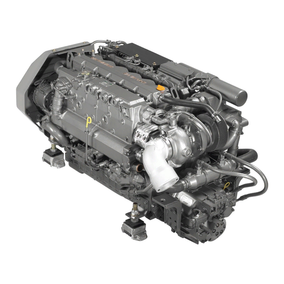
Sign In
Upload
Manuals
Brands
Yanmar Manuals
Engine
6LY3 series
Yanmar 6LY3 series Manuals
Manuals and User Guides for Yanmar 6LY3 series. We have
4
Yanmar 6LY3 series manuals available for free PDF download: Service Manual, Operation Manual, Technical Manual
Yanmar 6LY3 series Service Manual (390 pages)
Brand:
Yanmar
| Category:
Engine
| Size: 70.81 MB
Table of Contents
Section 3 General Service Information
15
Location of Safety Decals
13
Table of Contents
15
Safety Precautions
17
6LY3-ETP Exterior Views
18
Operation Side
18
Non-Operation Side
18
Diesel Fuel
20
Diesel Fuel Specifications
20
Engine Oil
22
Engine Oil Specifications
22
Marine Gear Oil
22
Engine Coolant
23
Handling of Coolant
23
Engine Outline Drawings
24
6Ly3-Etp / Stp / Utp (Yt-15 Mount)
24
6Ly3-Etp
25
Exhaust Gas Emission Regulations
26
Engine Identification
26
EPA Exhaust Gas Emission Standard
27
EPA Guarantee Conditions for Emission Standard
27
Engine Nameplate
28
Reduction and Reversing Gear
28
Principal Engine Specifications
29
Abbreviations and Symbols
30
Abbreviations
30
Symbols
30
Unit Conversions
31
Unit Prefixes
31
Units of Length
31
Units of Volume
31
Units of Mass
31
Units of Force
31
Units of Torque
31
Units of Pressure
31
Section 4 Periodic Maintenance
33
Periodic Maintenance
34
EPA Requirements
35
Inspection and Maintenance
35
Periodic Maintenance Schedule
36
Inspection and Maintenance of EPA Emission-Related Parts
37
Introduction
35
The Importance of Periodic Maintenance
35
Performing Periodic Maintenance
35
Yanmar Replacement Parts
35
Required EPA Maintenance
35
Safety Precautions
35
Periodic Maintenance Procedures
38
Inspect before Starting
38
After Initial 50 Hours of Operation
40
Every 50 Hours of Operation
42
Every 250 Hours of Operation
47
Every 500 Hours of Operation
57
Every 1000 Hours of Operation
60
Every 2000 Hours of Operation
61
Testing Engine Operation
63
Long-Term Storage
65
Section 5 Engine
67
Introduction
71
Safety Precautions
71
Disassembling the Engine and Components
72
Precautions before Engine Disassembly
72
Special Tools
73
Special Hand Tools
75
Measuring Instruments
78
Removing the Engine from the Vessel
84
Draining the Coolant
84
Draining the Engine Oil
84
Removing the Electrical Wiring
84
Removing the Fuel Filter and Fuel Hoses
85
Removing the Air Silencer
85
Removing the Mixing Elbow
85
Removing the Turbocharger
85
Removing the Coolant Hoses
85
Removing the Intercooler
85
Removing the Starter Motor
86
Removing the Alternator
86
Removing the Coolant Tank, Cooler and Pump
86
Removing the Seawater Pump
86
Removing the Oil Filter and Oil Cooler
86
Removing the Electronic Control Devices
86
Removing the Fuel Injection Lines
86
Removing the Fuel Injection Nozzles
87
Removing the Fuel Injection Pump
87
Removing the Rocker Arm Shaft Assembly
87
Removing the Cylinder Head
87
Removing the Marine Gear
87
Removing the Crankshaft Damper and Pulley
87
Removing the Drive Shaft Housing Cover
87
Removing the Flywheel and Flywheel Housing
87
Turning the Engine Block over
87
Removing the Oil Pan and Spacer
87
Inspecting the Cylinder Block and Components
88
Inspecting Oil Passages and Freeze Plugs
88
Dye Penetrant Inspection Procedure
88
Replacing Freeze Plugs
89
Fabricating a Freeze Plug Driver
90
Measuring the Cylinder Bores
90
Cylinder Head Components and Functions
92
Inspecting the Cylinder Head
94
Inspecting the Pistons and Piston Pins
102
Inspecting the Connecting Rods
107
Inspecting the Crankshaft
110
Inspecting the Camshaft and Tappets
114
Inspecting the Tappets
116
Inspecting the Push Rods
117
Inspecting the Timing Gear
117
Inspecting the Idler Gear
117
Indexing the Gear Timing Marks
118
Inspecting the Flywheel and Housing
119
Replacing the Ring Gear
119
Positioning Top Dead Center
119
Inspecting the Intake / Exhaust System
120
Assembling the Engine and Components
121
Precautions before Assembling the Engine
121
Installing the Tappets
121
Installing the Piston Cooling Nozzles
122
Installing the Camshaft Bearings
122
Installing the Crankshaft
123
Installing the Oil Pump
124
Installing the Drive Shaft Housing
125
Installing the Camshaft
125
Installing the Piston Assemblies
125
Installing the Oil Pan Spacer
126
Installing the Oil Intake and Delivery Tubes
126
Installing the Oil Pan
127
Installing the Flywheel Housing Oil Seal
127
Installing the Flywheel Housing
127
Installing the Seawater Pump
128
Installing the Idler Gear
128
Installing the Oil Pressure Regulating Valve
129
Installing the Coolant Passage Cover
129
Installing the Fuel Injection Pump
129
Installing the Flywheel
129
Installing the Cylinder Head Assembly
130
Installing the Intercooler
131
Installing the Intake Manifold
132
Installing the Marine Gear
132
Installing the Push Rod and Rocker Arm Shaft Assembly
132
Installing the Rocker Arm Cover
132
Installing the Coolant Pump
133
Installing the Drive Shaft Housing Cover
133
Installing the Crankshaft V-Pulley and Damper
133
Installing the Fuel Injection Nozzles
134
Installing the Heat Exchanger
136
Installing the Coolant Tank
136
Installing the Engine Oil Cooler
137
Installing the Engine Oil Filters
137
Installing the Engine Coolant Hoses
138
Installing the Engine Air Ducts
140
Installing the Engine Turbocharger
140
Installing the Mixing Elbow
141
Installing the Oil Lines for the Fuel Injection Pump
142
Installing the Alternator
142
Installing the Starter Motor
142
Section 6 Fuel System
143
Fuel System
144
Safety Precautions
145
Introduction
146
Specifications
147
Fuel System Diagram
148
Fuel Injection Pump / Governor / Timer
149
Fuel Injection Pump Components
150
Governor Components and Functions
152
Timer Components and Functions
153
Removing the Fuel Injection Pump
156
Installing the Fuel Injection Pump
159
Troubleshooting the Fuel Injection System
166
Fuel Injection Nozzle Components and Functions
168
Fuel Injection Nozzle Functions
168
Fuel Feed Pump Components and Functions
170
Fuel Feed Pump Components
171
Fuel Feed Pump Specifications
172
Disassembling the Fuel Feed Pump
172
Inspecting the Fuel Feed Pump
172
Assembling the Fuel Feed Pump
172
Testing the Fuel Feed Pump
173
Fuel Filter Components and Functions
175
Inspecting the Fuel Filter
176
Electronic Control System
177
Engine Control System Diagram
178
Sensors and Actuators
179
Injection Quantity Control Diagram
180
Injection Timing Control Diagram
181
Timer Phase Detection
182
ECU Control Data Management
183
ECU Data Flow
185
Section 7 Coolant System
187
Coolant System
189
Introduction
189
Safety Precautions
189
Coolant System Components and Functions
190
Coolant System Components
191
Seawater Pump Components and Functions
192
Disassembling the Seawater Pump
192
Inspecting the Seawater Pump
193
Assembling the Seawater Pump
194
Coolant Pump Components and Functions
195
Coolant System Components
196
Disassembling the Coolant Pump
197
Inspecting the Coolant Pump
197
Heat Exchanger Components and Functions
199
Heat Exchanger Components
199
Disassembling the Heat Exchanger
199
Inspecting the Heat Exchanger
200
Pressure Cap Operation
200
Inspecting the Pressure Cap
201
Coolant Recovery Tank Components and Functions
202
Installing the Coolant Recovery Tank
202
Coolant Recovery Tank Precautions
202
Thermostat Components and Functions
203
Inspecting the Thermostat
204
Testing the Thermostat
204
Seacock Components and Functions (Optional)
205
Seacock Precautions
205
Inspecting the Seacock
205
Bilge Pump and Strainer Components and Functions (Optional)
206
Bilge Pump Characteristics
207
Bilge Pump Durability
207
Bilge Pump Insulation
207
Bilge Pump Precautions
207
Bilge Pump Vibration Proof
207
Installing the Bilge Pump
207
Troubleshooting the Bilge Pump
209
Section 8 Lubrication
211
Introduction
213
Safety Precautions
213
Lubrication Components and Functions
214
Oil Pump Components and Functions
215
Oil Pump Specifications
215
Oil Pump Components
216
Removing the Oil Pump
217
Inspecting the Oil Pump
217
Installing the Oil Pump
217
Oil Pressure Control Valve Components and Functions
218
Replacing the Oil Pressure Control Valve
218
Oil Filter Components and Functions
219
Replacing the Oil Filter
219
Oil Cooler Components and Functions
220
Inspecting the Oil Cooler
220
Rotary Waste Oil Pump Components and Functions (Optional)
220
Rotary Waste Oil Pump Components
221
Inspecting the Waste Oil Pump
221
Section 9 Turbocharger
223
Introduction
225
Safety Precautions
225
Turbocharger Components and Functions
226
Turbine
227
Compressor
227
Bearings
227
Seal Structure of the Compressor Housing
227
Maintenance Standards
228
Standard Limits
228
Torque Chart
230
Turbocharger Periodic Inspections
231
Inspection Intervals
231
Checking the Rotor Rotation
231
Checking the Rotor Axial Play
232
Checking the Rotor Radial Play
233
Disassembling the Turbocharger
234
Special Tools
234
Inspecting the Turbocharger before Disassembling
236
Disassembling the Turbocharger
236
Inspecting the Turbocharger
237
Inspecting Major Items
237
Cleaning the Turbocharger
237
Inspecting the Turbocharger Components
238
Assembling the Turbocharger
241
Installing the Floating Bearings
241
Installing the Turbine Rotor Shaft
242
Installing the Thrust Bearing
242
Installing the Seal Plate
242
Installing the Compressor Impeller
243
Installing the Turbine Housing
243
Installing the Compressor Housing
243
Connecting the Boost Hose
243
Post-Assembly Inspection
243
Handling the Turbocharger
244
Precautions for Installing the Turbocharger to the Engine
244
Troubleshooting the Turbocharger
245
Black Smoke
245
White Smoke
246
Excessive Oil Consumption
246
Reduced Engine Power
246
Poor Follow-Up of the Turbocharger
246
Unusual Sound or Vibration
247
Section 10 Starter
249
Introduction
251
Safety Precautions
251
Starter Components and Functions
252
Starter Specifications
252
Starter Characteristics
253
Starter Components
254
Starter Operation
256
Starter Wiring Diagram
256
Section 11 Alternator
257
Safety Precautions
259
Introduction
260
Alternator Components and Functions (12V / 80A)
261
Alternator Specifications
261
Alternator Components
261
Alternator Wiring Diagram
264
Alternator Characteristics
265
Inspecting the Alternator
265
Section 12 Electrical and Ecu
267
Battery Components and Functions
269
Battery Capacity and Battery Cables
269
Inspecting the Battery
270
Charging the Battery
271
Precautions for Battery Storage
273
Safety Precautions
269
Wiring Diagram
274
ECU Connector Pin Configuration
275
Warning Devices
276
Sensor Locations
276
Sensors for Oil Pressure and Boost Pressure
278
Sensors for Water, Oil and Fuel Temperatures
278
Air Heater Components and Functions
279
Air Heater Operation
279
Fuse, Relay and Harness Components
282
Fuse Chart
282
Digital Display
287
Rocker Switch Panel
289
Control Head (Shift and Throttle)
290
Section 13 Troubleshooting
291
Troubleshooting
292
Introduction
293
Safety Precautions
293
Preparation before Troubleshooting
294
Teleflex Display Indications
294
Troubleshooting by Symptom
295
Troubleshooting Fuses, Relays and Harnesses
311
Fuse, Relay and Harness
311
Fuse Burns out
311
Test Check
311
Checking a Fuse
311
Troubleshooting Blown Fuses
312
Electronic Control System
316
Engine Control System Diagram
316
Terms
318
Troubleshooting by Dtc Fault Codes
318
List of DTC (Diagnostic Trouble Codes)
320
TFX Diagnostic Screen Display Procedure 3
320
Troubleshooting the Temperature Sensor
330
Troubleshooting the Pressure Sensor
344
Wiring Diagrams
371
Service Standards
381
Engine
381
Cylinder Head
382
Valve Spring
382
Camshaft and Gear Train
383
Idler Gear Shaft and Bushing
383
Cylinder Block
384
Piston and Ring
385
Connecting Rod
387
Tightening Torque for Bolts and Nuts
388
Main Bolt and Nut
388
Standard Bolts and Nuts (Without Oil)
389
Advertisement
Yanmar 6LY3 series Operation Manual (136 pages)
MARINE
Brand:
Yanmar
| Category:
Engine
| Size: 16.85 MB
Table of Contents
Introduction
3
Record of Ownership
4
Table of Contents
5
Table of Contents
9
Safety
9
Safety Precautions
10
Before You Operate
10
During Operation and Maintenance
11
Product Overview
29
Yanmar 6LY3 Features and Applications
29
Component Identification
30
Operation Side
30
Non-Operation Side
31
Location of Labels
32
Nameplate
33
Function of Major Components
34
Electronic Control System (ECS)
35
Display
36
Before You Operate
43
Fire and Explosion
44
Diesel Fuel
48
Diesel Fuel Specifications
48
Filling the Fuel Tank
49
Bleeding the Fuel System
51
Engine Oil
52
Engine Oil Specifications
52
Engine Oil Viscosity
53
Checking Engine Oil
53
Selection of Marine Gear Oil
53
Engine Coolant
54
Engine Coolant Specifications
55
Coolant (Fresh Water Cooling System)
55
Cranking
58
Daily Checks
59
Visual Checks
59
Check Diesel Fuel, Engine Oil, and Engine Coolant Levels
60
Checking and Refilling Marine Gear Oil
60
Checking the Control Head
60
Checking the Alarm Indicators
60
Preparing Fuel, Oil, and Coolant in Reserve
60
Engine Operation
61
Engine Operation
62
Starting the Engine
72
Before Starting the Engine
72
To Start the Engine
72
Shifting
74
Cautions During Operation
75
Shutting down the Engine
78
Normal Shutdown
78
Emergency Shutdown
78
Periodic Maintenance
81
Safety Precautions
81
Before You Operate
81
During Operation and Maintenance
82
Precautions
98
The Importance of Periodic Maintenance
98
Performing Periodic Maintenance
99
The Importance of Daily Checks
99
Keep a Log of Engine Hours and Daily Checks
99
Yanmar Replacement Parts
99
Tools Required
99
Ask Your Authorized Yanmar Marine Dealer for Help
99
Required EPA Maintenance - USA Only
100
EPA Installation Requirements - USA Only
100
Tightening Fasteners
100
Standard Torque Chart
100
Periodic Maintenance Schedule
101
Inspection and Maintenance of EPA Emission-Related Parts
103
Periodic Maintenance Procedures
104
After Initial 50 Hours of Operation
104
Oil Filter
104
Replace Engine Oil and Engine
104
Adjust the Propeller Shaft Alignment
106
Check the Electronic Control System Operation
106
Drain Fuel Filter and Fuel Filter / Water Separator
107
Every 50 Hours of Operation
107
Check the Battery
109
Adjust Alternator V-Belt Tension
111
Adjust Intake / Exhaust Valve Clearance (1St Time)
112
Check the Fuel Injector Spray Pattern
112
Every 250 Hours of Operation
112
Drain the Fuel Tank
113
Check the Seawater Pump Impeller
114
Replace the Engine Oil (Crankcase)
114
Replace the Engine Oil Filter Element
114
Replace the Fuel Filter Element
114
Clean the Air Intake Silencer
115
Replace the Anode
115
Check / Replace the Flexible Engine Mounts
116
Check the Wiring Connectors
116
Clean the Exhaust / Water Mixing Elbow
116
Clean the Turbocharger Blower
116
Flush the Aftercooler
116
Tighten All Major Nuts and Bolts
116
Adjust the Propeller Shaft Alignment
117
Check Alternator Belt Tension
117
Every 500 Hours of Operation
117
Replace Engine Coolant
117
Replace the Seawater Pump Impeller
117
Adjust Intake / Exhaust Valve Clearance
118
Check the Fuel Injector Spray Pattern
118
Clean and Check the Seawater Passages
118
Every 1000 Hours of Operation
118
Replace Alternator Belt
118
Replace Flexible Engine Mounts
118
Clean Engine Oil Cooler
119
Clean Seawater and Engine Coolant System
119
Every 2000 Hours of Operation
119
Overhaul and Check Fuel Feed Pump
119
Replace Rubber Fuel Hoses
119
EPA Requirements
120
EPA Certification Plates
120
Conditions to Ensure Compliance with EPA Emission Standards
120
Inspection and Maintenance
121
Troubleshooting
123
Troubleshooting Chart
124
Troubleshooting Information
125
Long-Term Storage
127
Before You Place the Engine in Long-Term Storage
127
Returning the Engine to Service
128
Specifications
129
Principal Engine Specifications
129
Epa Warranty Usa Only
131
Yanmar 6LY3 series Technical Manual (87 pages)
Electronic Control System
Brand:
Yanmar
| Category:
Engine
| Size: 4.8 MB
Table of Contents
Table of Contents
3
Components
7
System Overview
9
I5601E Digital Display
9
Specifi Cations
11
Main Menu
13
Control Head
25
Gauges
35
Specifi Cations
36
Specifi Cations
39
System Default Settings
45
NMEA 2000® Network
45
System Diagrams
50
Power Diagram Outline
53
Transmission Diagrams
59
Twin Disc
59
Cable Information
63
Key Switch Panel
67
Deutsch Connectors
69
Mounting Templates
72
St Station Ignition Panel - CP19100
74
St Station Key Swtich Panel - CE40100
76
Troubleshooting
79
Parts Information
81
Advertisement
Yanmar 6LY3 series Operation Manual (24 pages)
Electronic Control System
Brand:
Yanmar
| Category:
Engine
| Size: 6.33 MB
Table of Contents
Table of Contents
3
System Overview
4
Helm Components
4
Start up
5
Redundant (Back Up) Throttle
5
Shift & Throttle Control Head Functions
8
Control Head Operation
8
Operation
9
Detailed Operation of the Control Head
9
Control Head Button Functions
9
Control Station Selection
10
Indicator Dimming Feature
10
Shift Disconnect
11
Cruise Synchronization
12
Power Train Synchronization
12
Split Range Throttle
13
Trolling Mode (Option)
14
I5601E Digital Display Alarms/Diagnostic Code Screens
15
Engine Alarms
16
Engine Diagnostic Codes
16
Maintenance Warning
16
Diagnostics
17
Power Reduction Mode
17
Appendix A: I5601E Digital Display Setup
18
Unlocking" the Hot Keys
19
User Settings and Factory Settings
20
Quad Screen Parameters
21
Appendix B: I5601E Menu Navigation
22
Appendix C: Default Settings
23
Appendix D: Fuses
24
Appendix E: Trouble Codes
24
Advertisement
Related Products
Yanmar 6LY2A-STP
Yanmar 6LYA-STP
Yanmar 6LY3-STC
Yanmar 6LY3-UTC
Yanmar 6LYA-UTE
Yanmar 6LYA-STE
Yanmar 6LY3-UTP
Yanmar 6LY3-STP
Yanmar 6LY3-ETP
Yanmar 6LY2-STE
Yanmar Categories
Engine
Tractor
Portable Generator
Outboard Motor
Excavators
More Yanmar Manuals
Login
Sign In
OR
Sign in with Facebook
Sign in with Google
Upload manual
Upload from disk
Upload from URL