Sign In
Upload
Manuals
Brands
Wago Manuals
I/O Systems
750-512
Wago 750-512 Manuals
Manuals and User Guides for Wago 750-512. We have
2
Wago 750-512 manuals available for free PDF download: Manual
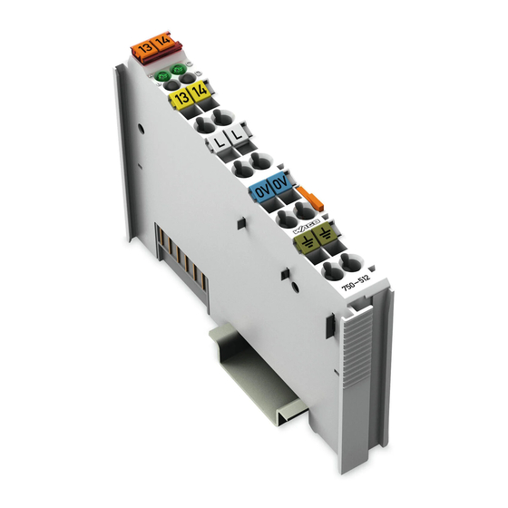
Wago 750-512 Manual (46 pages)
2DO 230V AC 2.0A/ Relay 2NO, 2-Channel Relay Output Module AC 230 V, DC 30 V, non-floating; 2 make contacts
Brand:
Wago
| Category:
I/O Systems
| Size: 1 MB
Table of Contents
Deutsch
3
Table of Contents
3
1 Notes about this Documentation
5
Validity of this Documentation
5
Copyright
5
Symbols
6
Number Notation
8
Font Conventions
8
Table 1: Number Notation
8
Table 2: Font Conventions
8
2 Important Notes
9
Legal Bases
9
Subject to Changes
9
Personnel Qualifications
9
Use of the 750 Series in Compliance with Underlying Provisions
9
Technical Condition of Specified Devices
10
Safety Advice (Precautions)
11
3 Device Description
13
View
15
Connectors
16
Data Contacts/Internal Bus
16
Power Jumper Contacts/Field Supply
17
Table 3: Power Jumper Contacts
17
CAGE CLAMP Connections
18
Table 4: Connectors
18
Display Elements
19
Operating Elements
19
Table 5: Display Elements
19
Schematic Diagram
20
Technical Data
21
Device Data
21
Power Supply
21
Communication
21
Outputs
21
Table 6: Technical Data Device
21
Table 7: Technical Data Power Supply
21
Table 8: Technical Data Communication
21
Table 9: Technical Data Inputs
21
Approvals
22
Standards and Guidelines
23
4 Mounting
24
Mounting Sequence
24
Inserting and Removing Devices
25
Inserting I/O Module
25
Removing the I/O Module
26
5 Connect Devices
27
Connecting a Conductor to the CAGE CLAMP
27
Connection Examples
28
2-Conductor Connection, Ungrounded
28
2-Conductor Connection, Grounded
28
3-Conductor Connection, Ungrounded
29
3-Conductor Connection, Grounded
29
6 Process Image
30
Table 10: Output Bits
30
7 Use in Hazardous Environments
31
Marking Configuration Examples
32
Marking for Europe According to ATEX and IEC-Ex
32
Table 11: Description of Marking Example for Approved I/O Modules According to ATEX and Iecex
33
Table 12: Description of Marking Example for Approved Ex I I/O Modules According to ATEX and Iecex
36
Marking for America According to NEC 500
37
Table 13: Description of Marking Example for Approved I/O Modules According to
37
Installation Regulations
38
Special Conditions for Safe Use (ATEX Certificate TÜV 07 ATEX 554086 X)
39
Special Conditions for Safe Use (ATEX Certificate TÜV 12 ATEX 106032 X)
40
Special Conditions for Safe Use (IEC-Ex Certificate TUN 09.0001
41
Special Conditions for Safe Use (IEC-Ex Certificate Iecex TUN 12.0039 X)
42
Ansi/Isa 12.12.01
43
English
44
Figure 1: View
15
Figure 2: Data Contacts
16
Fig 3: Power Jumper Contacts
17
Figure 4: Connectors
18
Figure 5: Display Elements
19
Figure 6: Schematic Diagram
20
Figure 7: Insert I/O Module
25
Figure 8: Snap the I/O Module into Place
26
Figure 9: Removing the I/O Module
26
Figure 10: Connecting a Conductor to a CAGE CLAMP
27
Figure 11: Connecting Diagram 2-Conductor Connection, Ungrounded
28
Figure 12: Connecting Diagram 2-Conductor Connection, Grounded
28
Figure 13: Side Marking Example for Approved I/O Modules According to ATEX and Iecex
32
Figure 14: Printing Text Detail - Marking Example for Approved I/O Modules According to ATEX and Iecex
32
Figure 15: Side Marking Example for Approved Ex I I/O Modules According to ATEX and Iecex
34
Figure 16: Text Detail - Marking Example for Approved Ex I I/O Modules According to ATEX and Iecex
34
Figure 17: Side Marking Example for I/O Modules According to NEC 500
37
Figure 18: Text Detail - Marking Example for Approved I/O Modules According to
37
List of Figures
44
List of Tables
45
Advertisement
WAGO 750-512 Manual (14 pages)
Fieldbus Independent I/O Modules 2D0 230V AC 2.0 A/ Relay 2NO
Brand:
WAGO
| Category:
Control Unit
| Size: 0 MB
Table of Contents
Table of Contents
3
Important Comments
4
Legal Principles
4
Copyright
4
Personnel Qualification
4
Intended Use
4
Symbols
5
Number Notation
5
Safety Notes
6
Scope
6
O Modules
7
Digital Output Modules
7
750-512 [2DO 230V AC 2.0 A/ Relay 2NO]
7
View
7
Description
7
Display Elements
8
Schematic Diagram
9
Technical Data
10
Process Image
11
Load Limiting Value Graph of the Relay
12
Contact Protective Circuit for Relay Modules
13
Advertisement
Related Products
WAGO I/O-SYSTEM 750 510 376 07
WAGO 750-514
WAGO 750-559/040-000
WAGO 750-554/000-200
WAGO 750-560
WAGO 750-556
WAGO 750-563
WAGO 750-531
WAGO 750-504
WAGO 750-530
Wago Categories
I/O Systems
Control Unit
Power Supply
Switch
Controller
More Wago Manuals
Login
Sign In
OR
Sign in with Facebook
Sign in with Google
Upload manual
Upload from disk
Upload from URL