Sign In
Upload
Manuals
Brands
WAGO Manuals
I/O Systems
750-559/040-000
WAGO 750-559/040-000 Analog Output Module Manuals
Manuals and User Guides for WAGO 750-559/040-000 Analog Output Module. We have
2
WAGO 750-559/040-000 Analog Output Module manuals available for free PDF download: Manual
WAGO 750-559/040-000 Manual (52 pages)
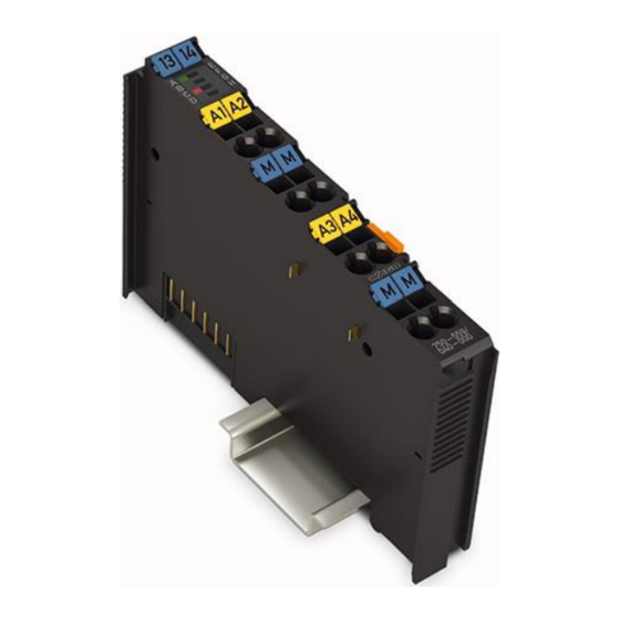
4AO 0-10V DC /XTR 4-Channel Analog Output Module, 0-10 VDC /XTR For WAGO-I/O-SYSTEM 750 XTR
Brand:
WAGO
| Category:
Control Unit
| Size: 1 MB
Table of Contents
Table of Contents
3
Figure 4: CAGE CLAMP
3
Notes about this Documentation
5
Validity of this Documentation
5
Copyright
5
Symbols
6
Number Notation
8
Font Conventions
8
Table 1: Number Notation
8
Table 2: Font Conventions
8
Important Notes
9
Legal Bases
9
Subject to Changes
9
Personnel Qualifications
9
Use of the 750 Series in Compliance with Underlying Provisions
9
Technical Condition of Specified Devices
10
Disposal
10
2.1.4.1.1 Electrical and Electronic Equipment
10
2.1.4.1.2 Packaging
11
Safety Advice (Precautions)
12
Device Description
15
View
17
Figure 1: View
17
Table 3: Legend for Figure "View
17
Connectors
18
Data Contacts/Local Bus
18
Figure 2: Data Contacts
18
Power Jumper Contacts/Field Supply
19
Figure 3: Power Jumper Contacts
19
Table 4: Legend for Figure "Power Jumper Contacts
19
CAGE CLAMP ® Connectors
20
Table 5: Legend for Figure "CAGE CLAMP
20
Display Elements
21
Operating Elements
21
Figure 5: Display Elements
21
Table 6: Legend for Figure "Display Elements
21
Schematic Diagram
22
Figure 6: Schematic Diagram
22
Technical Data
23
Device Data
23
Power Supply
23
Communication
23
Table 7: Technical Data - Device
23
Table 8: Technical Data - Power Supply
23
Table 9: Technical Data - Communication
23
Outputs
24
Connection Type
24
Mechanical Conditions
24
Table 10: Technical Data - Outputs
24
Table 11: Technical Data - Field Wiring
24
Table 12: Technical Data - Power Jumper Contacts
24
Table 13: Technical Data - Data Contacts
24
Table 14: Technical Data - Mechanical Conditions
24
Climatic Environmental Conditions
25
Table 15: Technical Data - Climatic Environmental Conditions
25
Approvals
26
Standards and Guidelines
27
Table 16: Standards and Rated Conditions for Explosion Protection Applications
27
Table 17: Climatic and Mechanical Environmental Conditions and Shipbuilding
28
Table 18: EMC - Immunity to Interference
29
Table 19: EMC - Emission of Interference
31
Table 20: Standards and Rated Conditions for Rail Applications (en 50155)
32
Process Image
33
Table 21: Process Image
33
Mounting
34
Mounting Sequence
34
Inserting and Removing Devices
35
Inserting the I/O Module
35
Figure 7: Insert I/O Module (Example)
35
Removing the I/O Module
36
Figure 8: Snap the I/O Module into Place (Example)
36
Figure 9: Removing the I/O Module (Example)
36
Connect Devices
37
Connecting a Conductor to the CAGE CLAMP
37
Figure 10: Connecting a Conductor to a CAGE CLAMP
37
Connection Example
38
Figure 11: Connecting Diagram
38
Use in Hazardous Environments
39
Marking Configuration Examples
40
Marking for Europe According to ATEX and Iecex
40
Figure 12: Marking Example According to ATEX and Iecex
40
Figure 13: Text Detail - Marking Example According to ATEX and Iecex
40
Table 22: Description of Marking Example According to ATEX and Iecex
41
Figure 14: Marking Example for Approved Ex I I/O Module According to ATEX and Iecex
42
Figure 15: Text Detail - Marking Example for Approved Ex I I/O Module According to ATEX and Iecex
42
Table 23: Description of Marking Example for Approved Ex I I/O Module According to ATEX and Iecex
43
Marking for the United States of America (NEC) and Canada (CEC)
44
Figure 16: Marking Example According to NEC
44
Figure 17: Text Detail - Marking Example According to NEC 500
44
Table 24: Description of Marking Example According to NEC 500
44
Figure 18: Text Detail - Marking Example for Approved
45
Figure 19: Text Detail - Marking Example for Approved
45
Table 25: Description of Marking Example for Approved
45
Table 26: Description of Marking Example for Approved
45
Figure 20: Text Detail - Marking Example for Approved
46
Table 27: Description of Marking Example for Approved
46
Installation Regulations
47
Special Notes Regarding Explosion Protection
47
Special Notes Regarding ANSI/ISA Ex
49
List of Figures
50
List of Tables
51
Advertisement
WAGO 750-559/040-000 Manual (52 pages)
4AO 0-10V DC /XTR 4-Channel Analog Output Module, 0-10 VDC /XTR
Brand:
WAGO
| Category:
I/O Systems
| Size: 2 MB
Table of Contents
Deutsch
3
Table of Contents
3
1 Notes about this Documentation
5
Validity of this Documentation
5
Copyright
5
Symbols
6
Number Notation
8
Font Conventions
8
Table 1: Number Notation
8
Table 2: Font Conventions
8
2 Important Notes
9
Legal Bases
9
Subject to Changes
9
Personnel Qualifications
9
Use of the WAGO-I/O-SYSTEM 750 in Compliance with Underlying Provisions
9
Technical Condition of Specified Devices
10
Safety Advice (Precautions)
11
3 Device Description
13
View
15
Table 3: Legend for Figure "View
15
Connectors
16
Data Contacts/Internal Bus
16
Power Jumper Contacts/Field Supply
17
Table 4: Legend for Figure "Power Jumper Contacts
17
CAGE CLAMP ® Connectors
19
Table 5: Legend for Figure "CAGE CLAMP ® Connectors
19
Display Elements
20
Operating Elements
20
Table 6: Legend for Figure "Display Elements
20
Schematic Diagram
21
Technical Data
22
Device
22
Supply
22
Communication
22
Table 7: Technical Data - Device
22
Table 8: Technical Data - Supply
22
Table 9: Technical Data - Communication
22
Outputs
23
Connection Type
23
Mechanical Conditions
23
Climatic Environmental Conditions
23
Table 10: Technical Data - Outputs
23
Table 11: Technical Data - Field Wiring
23
Table 12: Technical Data - Power Jumper Contacts
23
Table 13: Technical Data - Data Contacts
23
Table 14: Technical Data - Mechanical Conditions
23
Table 15: Technical Data - Climatic Environmental Conditions
23
Approvals
24
Standards and Guidelines
26
Table 16: Climatic and Mechanical Environmental Conditions
26
Table 17: EMC - Immunity to Interference
27
Table 18: EMC - Emission of Interference
28
4 Process Image
30
Table 19: Process Image
30
5 Mounting
31
Mounting Sequence
31
Inserting and Removing Devices
32
Inserting the I/O Module
32
Removing the I/O Module
33
6 Connect Devices
34
Connecting a Conductor to the CAGE CLAMP
34
Connection Example
35
7 Use in Hazardous Environments
36
Marking Configuration Examples
37
Marking for Europe According to ATEX and IEC-Ex
37
Table 20: Description of Marking Example for Approved I/O Modules According to ATEX and Iecex
38
Table 21: Description of Marking Example for Approved Ex I I/O Modules According to ATEX and Iecex
41
Marking for America According to NEC 500
42
Table 22: Description of Marking Example for Approved I/O Modules
42
Installation Regulations
43
Special Conditions for Safe Use (TÜV 14 ATEX 148929 X)
44
Special Conditions for Safe Use (ATEX Certificate TÜV 12 ATEX 106032 X)
45
Special Conditions for Safe Use (IEC-Ex Certificate TUN 14.0035X)
46
Special Conditions for Safe Use (IEC-Ex Certificate Iecex TUN 12.0039 X)
47
Special Conditions for Safe Use According to ANSI/ISA 12.12.01
48
English
49
Figure 1: View
15
Figure 2: Data Contacts
16
Figure 3: Power Jumper Contacts
17
Figure 4: CAGE CLAMP ® Connectors
19
Figure 5: Display Elements
20
Figure 6: Schematic Diagram
21
Figure 7: Insert I/O Module (Example)
32
Figure 8: Snap the I/O Module into Place (Example)
33
Figure 9: Removing the I/O Module (Example)
33
Figure 10: Connecting a Conductor to a CAGE CLAMP
34
Figure 11: Connecting Diagram
35
Figure 12: Side Marking Example for Approved I/O Modules According to ATEX and Iecex
37
Figure 13: Text Detail - Marking Example for Approved I/O Modules According to ATEX and Iecex
37
Figure 14: Side Marking Example for Approved Ex I I/O Modules According to ATEX and Iecex
39
Figure 15: Text Detail - Marking Example for Approved Ex I I/O Modules According to ATEX and Iecex
39
Figure 16: Side Marking Example for I/O Modules According to NEC 500
42
Figure 17: Text Detail - Marking Example for Approved I/O Modules
42
List of Figures
49
List of Tables
50
Advertisement
Related Products
WAGO 750-554
WAGO 750-554/000-200
WAGO 750-556
WAGO 750-556/000-200
WAGO 750-560
WAGO 750-563
WAGO 750-531
WAGO 750-504
WAGO 750-514
WAGO 750-504/025-000
WAGO Categories
I/O Systems
Control Unit
Power Supply
Switch
Controller
More WAGO Manuals
Login
Sign In
OR
Sign in with Facebook
Sign in with Google
Upload manual
Upload from disk
Upload from URL