Sign In
Upload
Manuals
Brands
Wacker Neuson Manuals
Excavators
28Z3
Wacker Neuson 28Z3 Manuals
Manuals and User Guides for Wacker Neuson 28Z3. We have
2
Wacker Neuson 28Z3 manuals available for free PDF download: Service Manual, Operator's Manual
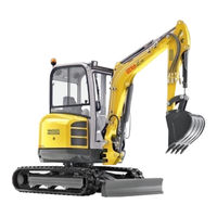
Wacker Neuson 28Z3 Service Manual (264 pages)
Track excavator
Brand:
Wacker Neuson
| Category:
Excavators
| Size: 17 MB
Table of Contents
Table of Contents
3
Notices on this Service Manual
12
Identification of Warnings and Dangers
13
Designated Use and Exemption from Liability
14
Type Labels and Component Numbers
15
Machine Overview
18
Cab Overview
19
Cab (Legend)
20
Instrument Panel Overview
21
Instrument Panel Legend
22
Overview of Open Engine and Valve Compartment
22
Engine Compartment: Overview
23
Chassis Overview
24
Valve Compartment
25
Stop and Park the Machine
26
Parking the Machine on Slopes
26
Specifications
27
Chassis
28
Engine
28
Fuel Injection Pump
28
Engine Capacities
29
Engine Tightening Torques
29
Hydraulic System
29
Work Hydraulics
29
Auxiliary Hydraulics Oil Flow 28Z3
30
Undercarriage and Swivel Unit
30
Stabiliser Blade
30
Electrical System
30
Noise Levels
31
Vibration
31
Coolant Compound Table
31
Powertilt
31
Model-Specific Tightening Torques
32
General Tightening Torques
32
Tightening Torques for Hydraulic Screw Connections (Dry Assembly)
32
Tightening Torques for High-Resistance Screw Connections
34
Dimensions Model 28Z3
36
Dimensions Model 28Z3 VDS
37
Lift Capacity Table 28Z3 (Short Stick)
39
Lift Capacity Table 28Z3 Long Stick (Option)
40
Lift Capacity Table 28Z3 Short Stick and Extra Weight (Option)
41
Lift Capacity Table 28Z3 Long Stick (Option) and Extra Weight (Option)
42
Lift Capacity Table 28Z3 VDS (Short Stick)
43
Lift Capacity Table 28Z3 Long Stick VDS (Option)
44
Kinematics
45
Maintenance
47
Fluids and Lubricants
48
Oil Grades for the Diesel Engine, Depending on Temperature
49
Additional Oil Change and Filter Replacement (Hydraulic System)
49
Oil Grades for the Hydraulic System, Depending on Temperature
50
Maintenance Label
51
Explanation of Symbols on the Maintenance Label
51
Maintenance Plan (Overview)
57
Service Package
57
Introduction
57
Safety-Relevant Parts
57
Fuel System
58
Refuelling
59
Emptying the Fuel Tank
59
Stationary Fuel Pumps
60
Diesel Fuel Specification
60
Bleeding the Fuel System
60
Water Separator
61
Replacing the Fuel Filter
62
Tank for Washer System
62
Engine Lubrication System
63
Checking the Oil Level
63
Filling up Engine Oil
64
Changing Engine Oil
65
Replacing the Engine Oil Filter Cartridge
66
Engine and Hydraulics Cooling System
67
Specific Safety Instructions
67
Checking/Filling up Coolant
68
Checking the Coolant Level
68
Filling up Coolant
69
Draining Coolant
69
Air Filter
70
Replacing Air Filter Elements
70
Air Intake
72
Change Cab Air Filter
73
V-Belt
74
Checking V-Belt Tension
74
Retightening the V-Belt
75
Pressure Check
77
General
77
Overview of Measuring Ports (up to Serial Number AG02712)
77
Overview of Measuring Ports (from Serial Number AG02713)
77
Checking Pilot Control Pressure
78
Pressure Check of Variable Displacement Pump P1
79
Pressure Check of Variable Displacement Pump P2
80
Pressure Check of Gear Pump P3
81
Secondary Pressure Limiting Valve of the Gear Motor
82
Primary Pressure Limiting Valves
82
Hydraulic System
87
Specific Safety Instructions
87
Checking the Hydraulic Oil Level
88
Filling up Hydraulic Oil
89
Changing Hydraulic Oil
90
Monitoring the Hydraulic Oil Return Filter
90
Replacing the Hydraulic Oil Filter
91
Draining Condensation Water from the Hydraulic Oil Tank
91
Important Information for the Use of Biodegradable Oil
92
Checking Hydraulic Pressure Lines
93
Pilot Valve
94
Travelling Drive
95
Checking the Oil Level and Filling up Oil
95
Draining Oil
95
Tracks
96
Checking Track Tension
96
Adjusting Track Tension
97
Maintenance of Attachments
98
Lubrication Points
98
Parking the Machine
98
Overview of Lubrication Points
99
Lubrication Points on the Stabiliser Blade and Stabiliser Blade Ram
100
Lubrication Points on the Swivelling Console and Slewing Ram
100
Lubrication Points on the Boom, Bucket and Stick Rams
101
Lubrication Points on the Boom and Stick
102
Lubrication Point on the Joint Rod
102
Lubrication Point on Ball Bearing Race of Live Ring
103
Lubrication Point of Live Ring Teeth
103
Lubrication Point of VDS Live Ring Teeth
104
VDS Lubrication Points (Option)
105
Powertilt Lubrication Points (Option)
105
Lubrication Points of Hydraulic Quickhitch (Option)
106
Lubrication Points of Mechanical Quickhitch (Option)
106
Cab
106
Electrical System
107
Service and Maintenance Work at Regular Intervals
107
Instructions Concerning Specific Components
107
Alternator
107
Battery
108
General Maintenance Work
109
Cleaning
109
General Instructions for All Areas of the Machine
109
Inside the Cab
109
Cleaning the Seat Belt
109
Exterior of the Machine
110
Engine Compartment
110
Shatter Protection
110
Screw Connections and Attachments
110
Pivots and Hinges
110
Preparatory Work before Taking out of Service
111
Maintenance if the Machine Is out of Service for a Longer Period of Time
111
Putting into Operation Again
111
Fire Extinguisher
112
Engine
113
3TNV76-NNS Engine Overview
114
Fuel System
116
Cooling System
117
Checking and Adjusting Valve Clearance
118
Lapping the Intake and Exhaust Valves
119
Tightening Order for Cylinder Head Bolts
119
Order for Removing the Cylinder-Head Bolts
119
Order for Mounting the Cylinder-Head Bolts
119
Checking the Injection Nozzles
120
Pressure Check
120
Checking the Nozzle Jet
121
Injection Time
121
Checking Injection Time
121
Setting Injection Time
123
Removing and Installing the Injection Pump
124
Removing the Injection Pump
124
Fitting the Injection Pump
125
Measuring and Adjusting the Engine Speed
126
Compression
126
Checking the Coolant Thermostat
127
Checking the Thermal Switch
127
Oil Pressure Switch
128
Checking the Coolant Circuit
128
Cleaning the Cooling Water Channels
128
Coolant and Fuel Hoses
128
Crankcase Vent
129
Replacing the Glow Plugs
129
Engine Trouble
130
Hydraulic System
133
Hydraulic Pump PVD-0B-23BP-8G3-5083A
134
Pump Unit: Exploded View
136
Pilot Oil Supply Unit
137
Dismantling the Hydraulic Pump
138
Assembling the Hydraulic Pump
140
Troubleshooting on the Hydraulic Pump
144
Main Valve Block
145
Ports
145
Main Control Lines (Legend)
146
Pump/Tank Lines
146
Main Valve Block Diagram
147
Pressure Limiting Valves
148
Pump Assignment
149
Drive Counterbalancing System
150
Pump Assignment for Drive Counterbalancing
150
Regeneration - Stick Section
151
Bucket Pre-Tension
151
Auxiliary Hydraulics Flow Rate Adjustment
152
Travelling Drive
153
Function
154
Swivel Unit
156
Swivel Unit Brake
157
Swivel Joint
159
Replace the Sealing Rings
159
Swivel Joint VDS (Option)
160
Pilot Valves
161
Joystick
161
Pilot Valve (Driving)
162
Changeover Valve for SAE/ISO Controls (Option)
164
Proportional Valve (Option)
164
Changeover Valve VDS (Option)
165
3/2 Directional Valve (Option)
165
Easy Lock Valve (Option)
165
Hydraulic Oil Tank Service Valve (Option)
166
Breather Filter
166
Auxiliary Hydraulics Connections
167
Troubleshooting in the Hydraulic System
168
Electrical System
175
Ohm's Law (Current, Voltage, Resistance); Power
176
Measuring Equipment, Measuring Methods
176
Cable Colour Coding
177
Relays
177
Use, Mode of Function
177
Socket
178
Electric Units
178
Fuse Box
178
Alternator
179
Starter
179
Switches: Overview
180
Switch Legend
180
Cigarette Lighter
181
Radio and Mounting/Wiring for Radio Installation (Option)
181
Front Working Light
182
Cab Lights (Option)
182
Rotating Beacon (Option)
183
Driving Signal (Option)
183
Driving Signal Wiring Harness (Option)
183
Counterweight
202
Specifications
202
Long Stick
202
Automatic Engine Speed Setting
203
Installation
204
Grab Pipework
205
Attachments
205
3Rd Control Circuit/Powertilt Ports
206
Safe Load Indicator
207
Safe Load Indicator de (from Serial No. AG04828) (Safety Valves for Boom)
208
Safe Load Indicator de (up to Serial No. AG02443)
210
Function
210
Setting the Pressure Switch
211
Safe Load Indicator FR (from Serial No. AG04828) (Safety Valves for Boom, Stick and Stabiliser Blade)
212
Safe Load Indicator FR (Serial Nos. AG02444 to AG04827) (Safety Valves for Boom, Stick and Stabiliser Blade)
213
Safe Load Indicator FR (up to Serial No. AG02443)
214
Function
214
Diagram (from Serial No. AG04828)
215
Diagram (Serial Nos. AG02444 to AG04827)
216
Diagram (up to Serial No. AG02443)
216
Setting the Pressure Switch
217
Hose Burst Valve Safety Feature
218
Mechanical Quickhitch
219
Hydraulic Quickhitch (Easy Lock)
220
3Rd Control Circuit
220
Function
220
Diagram
220
Drive Interlock (Antitheft Protection)
221
Position
221
Disabling the Drive Interlock
221
Enabling the Drive Interlock
221
Programming
221
Proportional Controls
223
Function
223
Ports
224
Measures to be Taken in Case of Malfunctions
224
Left-Hand Control Lever
224
Boom Swivel Controls
225
Auxiliary Hydraulics
225
Hammer Operation
225
Adjusting Control Response
226
Characteristic Curves - Status Indicator
226
Wiring Harness
227
Control Unit Connector Assignment
227
Measures to be Taken in Case of Malfunctions
228
Diagnosis Display
228
Engine Oil Service Valve
229
Function
229
Powertilt PTS06 General Instructions
232
General Safety Instructions
232
Checking the Product
233
Internal Decompression Valve
233
Testing the Hydraulic System of the Machine
233
Specifications/Requirements
234
Tools
235
Making a Tool VI for Removing the Seals
236
Separating the Bucket or Equipment from the Powertilt Swivel Device
236
Separating the Powertilt Swivel Device from the Machine
236
Exploded Views PTS06
237
PTS06 Components
237
Sealing Kit a and Bearing Kit B PTS06 (Overview)
238
Assembly Drawing
239
Removing the Standard Journal Coupling
240
Removing the End Cap, Securing Ring and Internal Decompression Valve
242
Removing the Shaft
243
Removing the Piston Tube Body
244
Removing the Seals (Kit A), Shaft Bearings and Pressure Discs (Kit B)
245
Checking Components and Dead Centre Marks
246
Trial Assembly
247
Installing the Seals (Kit A), Shaft Bearings and Pressure Discs (Kit B)
247
Installing the End-Cap Seals and Bearings
248
Installing the Piston Seals and Bearings
249
Fitting the Shaft Seal and the Bearing
250
Installing the Piston Tube
251
Installing the Shaft
252
Installing the End Cap and the Securing Ring
253
Installing the Internal Decompression Valve
254
Installing the Standard Journal Coupling
254
Lubrication and Tests
257
Lubrication
257
Test for Internal Leaks
257
Testing the Internal Decompression Valve
258
Securing the Powertilt Swivel Device on the Machine
259
Fitting a Bucket or Equipment Onto the Powertilt Swivel Device
259
Troubleshooting
260
Adjusting the Play on the Powertilt
261
Checking the Circumferential Play
261
Advertisement
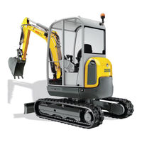
Wacker Neuson 28Z3 Operator's Manual (200 pages)
Track Excavator
Brand:
Wacker Neuson
| Category:
Excavators
| Size: 23 MB
Table of Contents
Table of Contents
21
Introduction
29
Important Operator Information
29
Machine Overview
30
Brief Description
31
Travelling Drive
31
Work Hydraulics
31
Cooling System
31
Cab
31
Fields of Application, Attachments
32
Use: Attachment
32
Operator Qualifications
33
EC Declaration of Conformity for Machines Delivered before the 29Th December 2009
34
Declaration of Conformity for Machines Without the CE Mark at the Type Plate
36
Type Labels and Component Numbers
37
Symbols (up to AG01685)
39
On the Outside of the Machine
39
Symbols (from AG01686)
43
Symbols
44
Safety Labels
46
Fire Extinguisher
51
Safety Information
53
Safety Symbols Found in this Manual
53
Warranty
54
Designated Use
54
Preparing to Use the Machine
54
Conditions for Use
54
User Training and Knowledge
55
Modifications and Spare Parts
55
Applications with Lifting Gear
55
Operator and Technician Qualifications and Basic Responsibilities
57
User/Owner Responsibility
57
Repair Person Qualifications
57
Safety Instructions Regarding Operation
57
Preparing for Use
57
Starting and Stopping
58
Work Area Awareness
58
Danger Area Awareness
58
Carrying Passengers
59
Mechanical Integrity
59
Traveling
59
Applications with Lifting Gear
60
General Information
60
Safety Criteria
60
Conditions for Safe Operation
60
Attachments
60
General Information Regarding Attachments
60
Installation Notes
61
Transport and Towing
61
Towing
61
Transporting
61
Safety Guidelines for Maintenance
61
General Maintenance Notes
61
Personal Safety Measures
62
Preparing for Maintenance and Repair Work
62
Performing Maintenance and Repairs
62
Special Hazards
63
Battery
63
Tracks
64
Electric Energy
64
Hydraulics
64
Noise
64
Msds
65
Gas, Dust, Steam, Smoke
65
Safety Guidelines While Using Internal Combustion Engines
65
Running the Engine
65
Fueling the Engine
65
Operation
67
Cab Overview
69
Instrument Panel Overview
71
Operating the Excavator
72
Putting the Machine into Operation for the First Time
72
Running-In Period
72
Check Lists
73
Start-Up Checklist
73
Operation Checklist
74
Parking Checklist
74
Operating the Excavator
75
Preheating / Start Switch: Overview
75
Throttle Lever: Overview
75
Indicator Lights and Warning Lights: Overview
76
Hydraulic Oil Filter Indicator Light (Red)
76
Indicator Light (Red) - Alternator Charge Function
76
Engine Oil Pressure Indicator Light (Red)
76
Coolant Temperature Indicator Light (Red)
76
Cold Starter Indicator Light (Yellow)
77
Fuel Level Indicator
77
Hour Meter
77
Before Starting the Engine
78
Starting the Engine: General
78
Procedure
78
Starting with the Drive Interlock (Option)
79
Starting at Low Temperatures
79
When the Engine Has Started
80
Engine Warm-Up
80
Jump-Starting the Engine (Supply Battery)
80
Safety Instructions
80
Special Instructions for Operating on Public Roads
82
Traveling Operation
82
Drive Levers
82
High Speed
83
Hydraulic Brake
83
Mechanical Brake
83
Operating on Slopes
84
Specific Safety Instructions
84
Operating on Slopes
85
Stabilizer Blade Operation
86
Stopping and Parking the Machine
87
Stop the Machine
87
Parking the Machine on Slopes
88
Light System
89
Roof Lights (Option)
89
Interior Light
90
Rotating Beacon (Option)
90
Cab Heating and Ventilation
90
Heating Adjustment
91
Washer System
91
Tank for Washer System
92
Seat
92
Seat Adjustment
92
Weight Adjustment
93
Horizontal Adjustment
93
Seat Belt
94
Emergency Exit
95
Front Window
96
Door
97
Side Window
98
Engine Cover
98
Exit through the Door
99
Armrest Adjustment
100
Towing the Track Excavator
100
Towing
100
Lifting Excavator
102
Loading and Transporting the Machine
103
Tying down the Excavator
104
Operating the Machine
105
General Safety Instructions
105
Control Levers/Control Pattern ''A'': Overview
106
Left-Hand Side Control Lever
106
Boom Swivel Controls
106
Auxiliary Hydraulics
107
Right-Hand Side Control Lever
107
Lowering the Boom with the Engine Stopped
108
Releasing Pressure
108
Rotating the Upper Carriage
108
Swivel Unit Brake
109
Changeover Valve for Control Pattern''b''(Option)
110
Left-Hand Side Control Lever
110
Right-Hand Side Control Lever
110
Directional Valve Position
110
Directional Valve
111
Control Lever with Proportional Controls (Option): Overview
112
Function
112
Measures to be Taken in Case of Malfunctions
113
Left-Hand Side Control Lever
113
Boom Swivel Controls
114
Auxiliary Hydraulics
114
Hammer Operation
114
Adjusting Control Response
115
Characteristic Curves - Status Display
115
Lowering the Boom with the Engine Switched off
116
Releasing Pressure
116
Rotating the Upper Carriage
117
Rotating Upper Carriage Brake
117
Control Lever if Equipped with 3Rd Control Circuit (Option): Overview
118
Left-Hand Side Control Lever
118
Boom Swivel Controls
118
Auxiliary Hydraulics
119
Right-Hand Side Control Lever
119
Lowering the Boom with the Engine Switched off
120
Releasing Pressure
120
Rotating the Upper Carriage
120
Rotating Upper Carriage
121
Releasing the Pressure on the Work Hydraulics
122
Releasing Pressure
122
Pressure Release with Proportional Controls (Option)
122
Coupling and Uncoupling Attachments
123
Specific Safety Instructions
123
Removing a Bucket
124
Mounting a Bucket
124
Quickhitch (Option)
125
Hydraulic Quickhitch (Option)
126
Maintenance
126
Operation
127
Powertilt (Option)
129
Re-Equipping
130
Mounting the Powertilt Unit
130
Removing the Powertilt Unit
130
Port
131
Operation
131
Right-Hand Side Control Lever (Powertilt)
132
Connections for Auxiliary Hydraulics
133
Grab Couplings
133
Attachments
134
Load Holding Control Valve (Option)
134
Working with the Excavator
135
Working with the Standard Bucket
135
Prohibited Operation
135
Excavator Work Position
137
Bucket Position When Digging
137
Excavating Trenches
137
Loading
138
Grading
138
Excavating Trenches Sideways
138
Working Alongside Trenches
139
Stabilizer Blade at Rear
139
Grading
141
Safe Load Indicator (Option)
141
Troubleshooting Engine Trouble
144
Malfunctions of the Powertilt Unit
145
Maintenance Introduction
147
Fuel System
148
Specific Safety Instructions
148
Refueling
148
Draining the Fuel
149
Stationary Fuel Pumps
149
Diesel Fuel Specification
150
Bleeding the Fuel System
150
Water Separator
151
Engine Lubrication System
152
Checking the Oil Level
152
Adding Engine Oil
153
Engine and Hydraulics Cooling System
154
Checking / Filling up Coolant
154
Specific Safety Instructions
155
Checking the Coolant Level
156
Draining Coolant
157
Air Filter
158
Replacing the Filter
158
V-Belt
160
Checking V-Belt Tension
160
Retightening the V-Belt
161
Hydraulic System
162
Specific Safety Instructions
162
Checking the Hydraulic Oil Level
163
Adding Hydraulic Oil
164
Important Information for the Use of Biodegradable Oil
165
Pilot Valve
166
Checking Hydraulic Pressure Lines
167
Tracks
168
Checking Track Tension
168
Adjusting the Track Tension
169
Track Propulsion Final Drive
170
Checking the Oil Level and Filling up Oil
170
Draining Oil
170
Maintenance of Attachments
171
Powertilt (Option)
171
Electric System
172
Specific Safety Instructions
172
Service and Maintenance Work at Regular Intervals
172
Instructions Concerning Specific Components
173
Alternator
173
Electric System
173
Battery
174
General Maintenance Work
175
Cleaning
175
General Instructions for All Areas of the Machine
175
Inside the Cab
176
Exterior of the Machine
176
Engine Compartment
176
Cleaning
176
Threaded Connections and Fasteners
177
Pivots and Hinges
177
Maintenance if the Machine Is out of Service for a Longer Period of Time
178
Preparatory Work before Taking the Machine out of Service
178
Putting the Machine into Operation Again
178
Fluids and Lubricants
179
Additional Oil Change and Filter Replacement (Hydraulics)
180
Maintenance Plan
180
Maintenance Label
186
Explanation of Symbols on the Maintenance Label
186
Specifications
189
Chassis
189
Engine
189
Hydraulic System
189
Undercarriage and Swivel Unit
190
Stabilizer Blade
190
Work Hydraulics
190
Electric System
191
Fuse Box in Engine Compartment
191
Noise Levels
192
Vibration
192
Coolant Compound Table
192
Powertilt
192
Dimensions Model 28Z3
193
Lift Capacity Table 28Z3
194
Lift Capacity Table 28Z3, Long Stick Option
195
Lift Capacity Table 28Z3, Extra Weight Option
196
Lift Capacity Table 28Z3, Long Stick and Extra Weight Options
197
Specifications
198
Advertisement
Related Products
Wacker Neuson 28Z3 VDS
Wacker Neuson 2503
Wacker Neuson PS 2 500
Wacker Neuson PS 2 750
Wacker Neuson PS 2 1503
Wacker Neuson PS 2 2203
Wacker Neuson PS 2 3703
Wacker Neuson 2001
Wacker Neuson 2500A
Wacker Neuson DPU 2560Hts
Wacker Neuson Categories
Power Tool
Construction Equipment
Water Pump
Portable Generator
Excavators
More Wacker Neuson Manuals
Login
Sign In
OR
Sign in with Facebook
Sign in with Google
Upload manual
Upload from disk
Upload from URL