Sign In
Upload
Manuals
Brands
Viessmann Manuals
Boiler
VITODENS 300-W
Viessmann VITODENS 300-W Manuals
Manuals and User Guides for Viessmann VITODENS 300-W. We have
7
Viessmann VITODENS 300-W manuals available for free PDF download: Service Manual, Technical Manual, Installation Instructions Manual, Technician Manual
Viessmann VITODENS 300-W Technical Manual (112 pages)
Brand:
Viessmann
| Category:
Boiler
| Size: 13 MB
Table of Contents
Table of Contents
2
Product Description
4
Specification
6
Gas Condensing Combi Boiler
9
Product Description
15
Specification
17
Product Description
21
Specification
23
Vitocell 100-W below the Boiler (Type CUGA and CUGA-A), Made from Steel, with Ceraprotect Enamel Coating
29
Delivered Condition
31
Vitocell 100-W Adjacent to the Boiler, Type CVA, CVAA and CVAA-A – 160, 200 and 300 L, White Finish, Made from Steel, with Ceraprotect Enamel Coating
32
Delivered Condition
35
Vitocell 300-W Adjacent to the Boiler, Type EVIA-A – 160 and 200 L, White Finish Heated by an Internal Indirect Coil, Made from Stainless Steel
36
Delivered Condition
37
Vitocell 100-W Adjacent to the Boiler, Type CVB and CVBB – 300 and 400 L, White Finish, Made from Steel with Ceraprotect Enamel Coating for Dual Mode DHW Heating
39
Delivered Condition
42
Vitocell 100-W Adjacent to the Boiler, Type CVUB and CVUC-A – 300 L, White Finish Made from Steel, with Ceraprotect Enamel Coating for Dual Mode DHW Heating
43
3 Vitodens 300-W
44
Separate Dhw Cylinders
44
Delivered Condition
45
Installation Accessories for Vitodens 200-W and 300-W
46
Installing the Vitodens 300-W Directly on a Wall
47
Installation of the Vitodens 300-W with Mounting Frame
50
Further Accessories
51
Connections between the Vitodens and the DHW Cylinder
53
Installation Accessories for Vitodens 222-W
54
Flue Gas Cascade (Positive Pressure) for Multi Boiler Systems with Vitodens 200-W and 222-W
55
Siting, Installation
56
Siting Conditions for Room Sealed Operation (Appliance Type C)
57
Electrical Connection
58
Gas Connection
59
Minimum Clearances
60
Pre-Installation with the Sub-Mounting Kit with Mixer – Installation on Finished Walls
62
Pre-Installation for Mounting the Vitodens 200-W and 300-W Directly on the Wall Installation on Unfinished Walls
64
Self-Supporting Installation of the Vitodens 200-W and 300-W
66
Pre-Installation Vitodens 222-W
68
Replacing Third Party Appliances with the Vitodens 200-W or 300-W
70
Replacing a Ceramini-Z-SR with a Vitodens 200-W or Vitodens 300-W (11-19 Kw)
71
Replacement of a Thermoblock-VC110E/-VC112E with a Vitodens 200-W or a Vitodens 300-W (11-19 Kw)
75
Replacement of a Thermoblock-VC/-VCW with a Vitodens 200-W or a Vitodens 300-W (26 And35 Kw)
77
Decision Making Aids for DHW Heating
80
Selection Tables, DHW Cylinders
81
Connections on the Water Side
82
Connections on the DHW Side
82
Condensate Connection
84
Condensate Drain Pipe and Neutralisation
85
Hydraulic Connection
86
General
86
Expansion Vessels
87
Low Loss Header
88
Intended Use
89
Control Units
89
Vitotronic 100, Type HC1B, for Constant Temperature Control
89
Layout and Functions
89
Specification Vitotronic 100, Type HC1B
90
Vitotronic 200, Type HO2B, for Weather-Compensated Operation
91
Design and Functions
91
Specification Vitotronic 200, Type HO2B
93
Vitotronic Accessories
93
Allocation to Control Unit Types
93
Vitotrol 100, Type UTA
94
Vitotrol 100, Type UTDB
94
External H4 Extension
95
Vitotrol 100, Type UTDB-RF
95
Notes Regarding Room Temperature Hook-Up (RS Function) for Remote Control Units
96
Information on the Vitotrol 200-A and Vitotrol 300-A
96
Vitotrol 200-A
96
Vitotrol 300-A
96
Information on the Vitotrol 200-RF and Vitotrol 300-RF
97
Vitotrol 200-RF
97
Vitotrol 300-RF with Table-Top Dock
98
Vitotrol 300-RF with Wall Mounting Bracket
99
Wireless Base Station
99
Wireless Outside Temperature Sensor
100
Wireless Repeater
100
Room Temperature Sensor
101
Immersion Temperature Sensor
101
Mounting Base for Programming Unit
102
Radio Clock Receiver
102
KM BUS Distributor
102
Mixer Extension Kit with Integral Mixer Motor
102
Mixer Extension Kit for Separate Mixer Motor
103
Immersion Thermostat
104
Contact Thermostat
104
Solar Control Module, Type SM1
105
Internal H1 Extension
106
Internal H2 Extension
106
AM1 Extension
106
EA1 Extension
107
Vitoconnect 100, Type OPTO1
108
LON Connecting Cable for Data Exchange between Control Units
108
Extension of the Connecting Cable
109
Terminator (2 Pce)
109
LON Communication Module
109
8.1 Regulations / Directives
109
Appendix
109
Regulations and Directives
109
Keyword Index
110
Advertisement
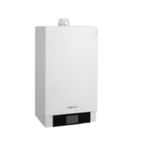
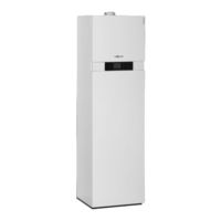
Viessmann VITODENS 300-W Technical Manual (104 pages)
VITODENS Series Gas condensing boiler
Brand:
Viessmann
| Category:
Boiler
| Size: 6 MB
Table of Contents
Table of Contents
2
Product Description
4
Specification
6
Product Description
13
Specification
15
Product Description
20
Specification
22
Vitocell 100-W (Type CUG) below the Boiler, Made from Steel, with Ceraprotect Enamel Coating
29
3 Vitodens 300-W
30
Separate Dhw Cylinders
30
Delivered Condition
31
Vitocell 100-W Adjacent to the Boiler (Type CVA - 160, 200 and 300 L, White Finish), Made from Steel, with Ceraprotect Enamel Coating
32
Delivered Condition
34
Vitocell 300-W Adjacent to the Boiler (Type EVA – 160 and 200 Litre, White Finish), Heated by a Peripheral Indirect Coil, Made from Stainless Steel
35
Delivered Condition
36
Vitocell 100-W Adjacent to the Boiler (Type CVB – 300 and 400 L White Finish), Made from Steel with Ceraprotect Enamel Coating for Dual Mode DHW Heating
37
Delivered Condition
39
Vitocell 100-W Adjacent to the Boiler (Type CVUA – 300 L, White Finish), Made from Steel with Ceraprotect Enamel Coating for Dual Mode DHW Heating
40
Delivered Condition
41
Installation Accessories for Vitodens 200-W and 300-W
42
Installation with a Sub-Mounting Kit
43
Installation of the Vitodens 300-W with Mounting Frame
45
Further Accessories
46
Connections between the Vitodens and the DHW Cylinder
47
Installation Accessories Vitodens 222-W
49
Flue Gas Cascade (Positive Pressure) for Multi Boiler Systems with Vitodens 200-W and 222-W
50
Positioning, Installation
51
Installation Conditions for Balanced Flue Operation (Appliance Type C)
52
Gas Connection
54
Pre-Installation with the Sub-Mounting Kit with Mixer – Installation on Finished Walls
55
Pre-Installation for Mounting the Vitodens 200-W and 300-W Directly on the Wall Installation on Unfinished Walls
56
Pre-Installation with Mounting Frame
57
Self-Supporting Installation of the Vitodens 200-W and 300-W
58
Pre-Installation for Vitodens 222-W
59
Replacing Third Party Appliances with the Vitodens 200-W or 300-W
61
Replacing a Ceramini-Z-SR with a Vitodens 200-W (3.2-19 Kw) or a Vitodens
62
Replacing a Cerastar-ZR/-ZWR with a Vitodens 200-W (5.2-35 Kw) or a Vitodens 300-W (4.0-35 Kw)
63
Replacing a Thermoblock-VC110E/-VC112E with a Vitodens 200-W (3.2-19 Kw) or a Vitodens 300-W (1.9-19 Kw)
65
Replacing a Thermoblock-VC/VCW with a Vitodens 200-W (5.2-35 Kw) or a Vitodens 300-W (4.0-35 Kw)
67
Decision-Making Aids Regarding DHW Heating
68
Information about Water Quality
68
Separate DHW Cylinders
69
Sizing Cylinders
69
Selection Tables, DHW Cylinders
70
Connections on the Water Side
70
Connections on the DHW Side
70
Condensate Connection
73
Condensate Drain and Neutralisation
73
Hydraulic Connection
75
General Information
75
Expansion Vessels
76
Low Loss Header
76
Intended Use
77
Control Units 7.1 Vitotronic 100, Type HC1B, for Constant Temperature Operation
78
Layout and Functions
78
Specification Vitotronic 100, Type HC1B
79
Vitotronic 200, Type HO1B, for Weather-Compensated Operation
79
Specification Vitotronic 200, Type HO1B
81
Vitotronic 200 RF, Type HO1C, for Weather-Compensated Operation
81
Specification Vitotronic 200 RF, Type HO1C
84
Vitotronic Accessories
84
Allocation to Control Unit Types
84
Vitotrol 100, Type UTA
85
Vitotrol 100, Type UTDB
85
External Extension H4
86
Vitotrol 100, Type UTDB-RF
86
Notes Regarding Room Temperature Hook-Up (RS Function) for Remote Control Units
87
Information on the Vitotrol 200A and Vitotrol 300A
87
Vitotrol 200A
87
Vitotrol 300 a
87
Vitocomfort 200
88
Information on the Vitotrol 200 RF and Vitotrol 300 RF
88
Vitotrol 200 RF
88
Vitotrol 300 RF with Table-Top Dock
89
Vitotrol 300 RF with Wall Mounting Bracket
90
Wireless Base Station
90
Wireless Outside Temperature Sensor
91
Wireless Repeater
91
Room Temperature Sensor
92
Immersion Temperature Sensor
92
Mounting Base for Programming Unit
93
Radio Clock Receiver
93
KM BUS Distributor
93
Mixer Extension Kit with Integral Mixer Motor
93
Mixer Extension Kit for Separate Mixer Motor
94
Immersion Temperature Controller
95
Contact Temperature Controller
95
Solar Control Module, Type SM1
95
Internal Extension H1
96
Internal Extension H2
96
Extension AM1
97
Extension EA1
97
Vitocom 100, Type LAN1
98
Vitocom 100, Type GSM2
98
Vitocom 200
99
LON Connecting Cable for Data Exchange between Control Units
101
Extension of the Connecting Cable
101
Terminator (2 Pce)
101
LON Communication Module
101
Appendix 8.1 Regulations / Directives
101
Regulations and Directives
101
8. Appendix
103
Keyword Index
103
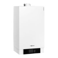
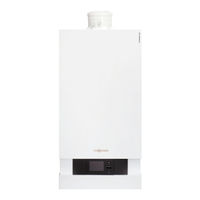
Viessmann VITODENS 300-W Technical Manual (96 pages)
Gas condensing boiler 3.8 to 35.0 kW
Brand:
Viessmann
| Category:
Boiler
| Size: 5 MB
Table of Contents
Table of Contents
2
Vitodens 200-W 1.1 Product Description
4
Specification
6
Vitodens 222-W 2.1 Product Description
14
Specification
16
Vitodens 300-W 3.1 Product Description
22
Specification
24
Separate DHW Cylinders 4.1 Vitocell 100-W (Type CUG – 120 and 150 Litres), below Made from Steel with Cerapro Tect Enamel Coating
29
Delivered Condition
30
Vitocell 100-W, Adjacent, (Type CVA – 160, 200 and 300 Litres, White Finish) Made from Steel with Ceraprotect Enamel Coating
32
Delivered Condition
34
Vitocell 300-W, Adjacent (Type EVA – 160 and 200 Litre, White Finish), with Peripheral Indirect Coil, Made from Stainless Steel
35
Delivered Condition
36
Vitocell 100-W, Adjacent (Type CVB – 300 and 400 Litres, White Finish), Made from Steel with Ceraprotect Enamel Coating for Dual Mode DHW Heating
37
Delivered Condition
39
Vitocell 100-W, Adjacent (Type CVUA – 300 Litres, White Finish), Made from Steel with Ceraprotect Enamel Coating for Dual Mode DHW Heating
40
Delivered Condition
41
Installation Accessories 5.1 Installation Accessories for the Vitodens 200-W and 300-W
42
Installation Directly Onto a Wall
42
Installation with a Sub-Mounting Kit
42
Installation with a Self-Supporting Mounting Frame
45
Installation with Mounting Frame
45
Additional Accessories
46
Connection between the Vitodens and the DHW Cylinder
47
Installation Accessories for the Vitodens 222-W
48
Installation Aid for Finished Walls
48
Installation Aid for Unfinished Walls
48
Additional Accessories
48
Flue Gas Cascade (Positive Pressure) for Multi-Boiler Systems with Vitodens 200-W and 222-W
49
Design Information 6.1 Positioning, Installation
50
Installation Conditions for Open Flue Operation (Appliance Type B)
50
Installation Conditions for Balanced Flue Operation (Appliance Type C)
50
Operation of the Vitodens in Wet Areas
51
Electrical Connection
51
Gas Connection
52
Minimum Clearances
53
Pre-Installation for Mounting the Vitodens 200-W and 300-W Directly on the Wall – Installation on Finished Walls
53
Pre-Installation with the Sub-Mounting Kit with Mixer – Installation on Finished Walls
54
Pre-Installation for Mounting the Vitodens 200-W and 300-W Directly on the Wall – Installation on Unfinished Walls
55
Pre-Installation with Mounting Frame
56
Self-Supporting Installation of the Vitodens 200-W and 300-W
57
Pre-Installation of the Vitodens 222-W
58
Replacement of Third Party Appliances with the Vitodens 200-W and 300-W
60
Replacing a Ceramini-Z-SR with a Vitodens 200-W (4.8-19 Kw) or a Vitodens
61
W (3.8-19 Kw)
61
Replacing a Cerastar-ZR/-ZWR with a Vitodens 200-W (6.5-35 Kw) or a Vitodens 300-W (5.2-35 Kw)
62
Replacing a Thermoblock-VC110E/-VC112E with a Vitodens 200-W (4.8-19 Kw) or a Vitodens 300-W (3.8-19 Kw)
64
Replacing a Thermoblock-VC/-VCW with a Vitodens 200-W (6.5-35 Kw) or a Vitodens 300-W (5.2-35 Kw)
66
Decision-Making Aids Regarding DHW Heating
67
Information about Water Quality
67
3 Vitodens 300-W
68
Separate DHW Cylinders
68
Sizing Cylinders
68
Selection Tables, DHW Cylinders
69
Connections on the Water Side
69
Connections on the DHW Side
69
Condensate Connection
72
Condensate Drain and Neutralisation
72
Hydraulic Connection
74
General
74
Expansion Vessels
74
Low Loss Header
75
Control Units 7.1 Vitotronic 100, Type HC1A, for Constant Temperature Operation
77
Structure and Functions
77
Specification Vitotronic 100, Type HC1A
78
Vitotronic 200, Type HO1A, for Weather-Compensated Operation
78
Specification Vitotronic 200, Type HO1A
80
Vitotronic Accessories
80
Allocation to Control Unit Types
80
Vitotrol 100, Type UTA
81
Vitotrol 100, Type UTDB
81
External Extension H4
82
Vitotrol 100, Type UTDB-RF
82
Notes Regarding Room Temperature Hook-Up (RS Function) for Remote Control Units
83
Information Regarding the Vitotrol 200A and 300A
83
Vitotrol 200A
83
Vitotrol 300A
83
Room Temperature Sensor
84
Mounting Base for Programming Unit
84
Radio Clock Receiver
85
Vitocom 100, Type GSM
85
Extension Kit for One Heating Circuit with Mixer with Integral Mixer Motor
85
Extension Kit for One Heating Circuit with Mixer for Separate Mixer Motor
86
Immersion Thermostat
87
Contact Thermostat
87
Solar Control Module, Type SM1
88
LON Communication Module
89
LON Connecting Cable for Data Exchange between Control Units
89
Extension of the Connecting Cable
89
Terminator (2 Pce.)
89
KM BUS Distributor
89
Immersion Temperature Sensor
90
Internal Extension H1
90
Internal Extension H2
90
Extension AM1
90
Extension EA1
91
Appendix 8.1 Regulations / Directives
91
Regulations and Directives
91
8. Appendix
93
Keyword Index
93
Advertisement
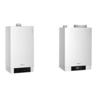
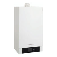
Viessmann VITODENS 300-W Service Manual (124 pages)
Wall mounted gas fired condensing boiler Natural gas and LPG version
Brand:
Viessmann
| Category:
Boiler
| Size: 5 MB
Table of Contents
Safety Instructions
2
Table of Contents
4
Commissioning, Inspection, Maintenance
5
Steps - Commissioning, Inspection and Maintenance
5
Further Details Regarding the Individual Steps
7
Filling the Heating System
7
Venting the Boiler
8
Venting the Heating System
8
Filling the Siphon with Water
9
Setting the Time and Date (if Required) Only for Weather-Compensated Control Units
10
Selecting the Language (if Required) Only for Weather-Compensated Control Units
10
Checking the Gas Type
11
Gas Type Conversion (Only for Operation with LPG)
12
Function Sequence and Possible Faults
12
Checking the Static and Supply Pressure
14
Setting the Maximum Output
15
Checking the Balanced Flue System for Tightness (Annular Gap Check)
16
Removing the Burner and Checking the Burner Gasket (Replace Gasket Every 2 Years)
17
Checking the Burner Gauze Assembly
18
Checking and Adjusting the Ignition and Ionisation Electrodes
19
Cleaning the Combustion Chamber/Heating Surfaces and Fitting the Burner
20
Checking the Diaphragm Expansion Vessel and System Pressure
21
Checking the Condensate Drain and Cleaning the Siphon
21
Checking All Gas Equipment for Tightness at Operating Pressure
22
Checking the Combustion Quality
22
Matching the Control Unit to the Heating System
23
Adjusting the Heating Curves (Only for Weather-Compensated Control Units)
29
Connecting the Control Unit to the LON System (Only for Weather-Compensated Control Units)
32
Instructing the System User
34
Scanning and Resetting the "Service" Display
34
Coding
36
Code 1
36
Code 2
39
Resetting Codes to Their Delivered Condition
60
Service Scans
61
Service Level Overview
61
Temperatures, Boiler Coding Card and Brief Scans
62
Checking Outputs (Relay Test)
65
Scanning Operating Conditions and Sensors
67
Troubleshooting
69
Fault Display
69
Troubleshooting Fault Display
70
Fault Codes
71
Repairs
82
Control and Display Elements
89
Heating Operation
89
Function Description
89
Constant Temperature Control Unit
89
Weather-Compensated Control Unit
90
Dhw Heating
91
Internal Extension H1
92
Extensions for External Connections (Accessories)
93
External Extension H
94
Control Functions
96
Remote Control DIP Switches
102
Electronic Combustion Control Unit
103
Designs
105
Connection and Wiring Diagram Internal Connections
105
Connection and Wiring Diagram External Connections
107
Connection and Wiring Diagram
108
Parts Lists
109
Commissioning/Service Reports
115
Specification
116
Certificates
117
Declaration of Conformity
117
Manufacturer's Certificate According to the 1St Bimschv [Germany]
118
Keyword Index
119
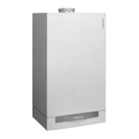
Viessmann VITODENS 300-W Technical Manual (68 pages)
Flue systems for gas condensing boilers VITODENS series; VITOSOLAR series up to 150.0 kW
Brand:
Viessmann
| Category:
Boiler
| Size: 4 MB
Table of Contents
Index Index
2
Table of Contents
2
Flue Systems
4
System Certification
4
Room Sealed Operation
4
Using Third Party Flue Systems
5
Open Flue Operation
5
Flue Gas High Limit Safety Cut-Out
5
Lightning Protection
5
CE Designation for Pps Flue Systems (Rigid and Flexible) for the Vitodens
6
Flue System Installation Options for Room Sealed Operation
8
Inside Occupied Rooms (Living Space) with One or more Full Storeys above
8
In Occupied Rooms (Living Space) Immediately below the Roof or with Only the Roof Space above
9
In the Installation Room, with Ventilation Air Supplied through the External Wall
9
Several Vitodens in the Living Space or in Living Spaces
10
Flue System Installation Options for Open Flue Operation
10
In the Installation Room (Non-Living Space) with One or more Full Floors above
10
Flue Gas Header for Several Vitodens 100-W, 200-W, 222-W, 222-F and 242-F - Positive Pressure
11
Special Version: Open Flue Operation and Installation Location in the Living Space with Combustion Air Supply Via Interconnected Rooms (Rated Heating Output ≤ 35 Kw)
11
Flue Gas Header for Several Vitodens - Negative Pressure
12
Boiler Allocation - Balanced Flue Pipe Size
12
Installing Flue Pipes
12
Installation and Position of Inspection Ports
13
Plastic (PP) Balanced Flue System for Routing in a Shaft - for Room Sealed Operation
13
93X to CEN/TR 1749)
13
Internal Shaft Dimensions to DIN V 18160
13
Flue, System Size 60, 80 and 110 (Components) (Type C 93X to CEN/TR 1749)
15
Vitodens in Conjunction with Solid Fuel Boilers
16
Cen/Tr 1749)
18
Flue, Flexible, System Size 60, 80 and 110 (Components) (Type C
18
Plastic (Pps) Balanced Flue System for Vertical Roof Outlets through a Pitched or Flat
19
33X to CEN/TR 1749)
19
For Vertical Roof Outlets When the Vitodens Is Installed in Attics
19
Vertical Flat Roof Outlet
19
Plastic (Pps) Balanced Flue System for External Wall Connection
21
Cen/Tr 1749)
21
Max. Total Length of the Flue Pipe
21
83X to CEN/TR 1749)
22
Separate Ventilation Air and Flue Gas Routing (Type C 83 to CEN/TR 1749)
22
Design and Sizing Information for Connection on the Flue Gas Side (Cont.)
23
Plastic (Pps) Balanced Flue System for Routing over External Walls
25
Bend 87° and 1 Support Bend
25
Bends 45° and 1 Support Bend
25
Cen/Tr 1749)
25
Connection Pipe D 1 M Long
25
Max. Length - System Size 60/60
25
Mum Flue Lengths
25
Standard Boiler Delivery)
26
Max. Total Flue Length up to the Boiler Flue Connection
27
Boiler Flue Connection (Part of the 60/100 80/125
27
Plastic (Pps) Balanced Flue System for Routing through a Lightweight Shaft
27
UNIFIX" Shaft Profiles from Skoberne (Made from Aerated Concrete)
27
Vitodens 100-W and 111-W Rated Heating Output Range
27
Vitodens 200-W, 222-F, 222-W and 242-F Rated Heating Output Range
27
Ø 80/125 MM to Ø 60/100 MM
27
Anchoring for Roof Outlets with Shaft Profiles
28
Shaft Profiles from Promat
28
Skobifixnano" and "Skobifixxs 30" Shaft Elements from Skoberne (Made from Foamed Ceramics)
28
Roof Outlet for Shafts with Promat Profiles
29
Plastic (Pps) Balanced Flue System for Routing Multiple Pipes through a Shaft
29
Layout Examples
30
Plastic (Pps) Balanced Flue System (Connection Line) for Connecting Multiple Flues to a Single Balanced Flue System
30
14(3)X to CEN/TR 1749)
31
Balanced Flue System, Negative Pressure
31
23 /B 33 to CEN/TR 1749)
33
Plastic (Pps) Flue Pipe for Routing through a Shaft - Open Flue Operation
35
Plastic (Pps) Flue Pipe for Routing through a Shaft - Open Flue Operation (Type B According to CEN/TR 1749)
35
Internal Shaft Dimensions
36
Flue, System Size 60, 80 and 110 (Components) (Type B
37
Flexible Flue, System Size 60, 80 and 110 (Components) (Type B According to
39
To CEN/TR 1749)
40
Multi Boiler Systems with Flue Systems under Positive Pressure (Open Flue Opera Tion)
42
Multi Boiler Systems with Flue Systems under Negative Pressure
49
Components for Routing a Flue over an External Wall
54
External Wall Components for Multiple Connections
56
Components for Multiple Connections to a Balanced Flue System – Positive Pressure for Vitodens 200-W, 222-W and 222-F, 19 to 26 Kw
60
Components of the Flexible Single Pipe System for Flexible Flues
61
Components for Multi Boiler Systems
63
Roof Elements
64
Rated Heating Output Range Kw
27
Balanced Flue Adaptor
27
Max. Length - System Size 60/100 M
27
Max. Length - System Size 80/125 M
27
Keyword Index
65
Viessmann VITODENS 300-W Technician Manual (60 pages)
Flue systems for gas condensing boilers 3.8 to 105.0 kW
Brand:
Viessmann
| Category:
Boiler
| Size: 2 MB
Table of Contents
Table of Contents
2
Balanced Flue Operation
4
Structural Unit
4
System Certification
4
Flue Gas High Limit Safety Cut-Out
5
Lightning Protection
5
Open Flue Operation
5
CE Certification for the Pps Flue Systems (Rigid and Flexible) for the Vitodens
6
Flue Installation Options for Balanced Flue Operation
8
Inside the Living Space (Occupied Areas) with One or more Full Floors above
8
Inside the Living Space (Occupied Area) Immediately Underneath the Roof or with Only Attics above (Rated Output ≤ 50 Kw)
9
Several Vitodens in the Living Space or in Occupied Rooms
9
Flue Installation Options for Open Flue Operation
9
Inside the Installation Location (Non-Living Space) with One or more Full Floors above (Compulsory for the Vitodens 200-W from 60 Kw)
10
Special Version: Open Flue Operation and Installed in the Living Space (Occupied Area) with Combustion Air Interconnection (Rated Output ≤ 35 Kw)
10
Flue Gas Header for Several Vitodens 200-W, 222-W and 222-F – Positive Pressure
11
Flue Gas Header for Several Vitodens - Negative Pressure
11
Plastic (Pps) Balanced Flue System for Routing through a Shaft - Balanced Flue Operation (Type C to TRGI 2008)
11
Internal Shaft Dimensions to DIN V 18160
12
Flue, System Size 60, 80 and 100 (Components) (Type C
13
Vitodens in Conjunction with Solid Fuel Boilers
14
Flue, Flexible, System Size 60, 80 and 100 (Components) (Type C
16
Plastic (Pps) Balanced Flue System for Vertical Routing through a Pitched or Flat Roof (Type C to TRGI 2008)
17
For Vertical Roof Outlets When the Vitodens Is Installed in Attics
17
Vertical Flat Roof Outlet
17
Plastic (Pps) Balanced Flue System for External Wall Connection
19
Max. Total Length of the Flue Pipe
19
Plastic (Pps) Balanced Flue System for Routing over External Walls (Type C 2008)
20
Plastic (Pps) Balanced Flue System for Routing through a Lightweight Shaft
21
UNIFIX" Shaft Profiles Offered by Skoberne (Made from Aerated Concrete)
22
Skobifixnano" and "Skobifixxs 30" Shaft Profiles Offered by Skoberne (Made from Foamed Ceramics)
22
Anchoring for Roof Outlets with Shaft Profiles
22
Promat Shaft Profiles
23
Roof Outlet for Shafts with Promat Profiles
24
Plastic (Pps) Balanced Flue System for Routing Multiple Pipes through a Shaft
24
Layout Examples
24
Plastic (Pps) Balanced Flue System (Connection Line) for Connecting Multiple Flues to a Single Room Sealed Balanced Flue System
25
Room Sealed Balanced Flue System, Negative Pressure
26
43X to TRGI 2008)
26
Plastic (Pps) Flue Pipe for Routing through a Shaft with Open Flue Operation (Type B According to TRGI 2008)
29
Internal Shaft Dimensions
29
Flue, System Size 60, 80 and 100 (Components) (Type B 23 /B 33 2008)
30
To TRGI 2008)
31
To TRGI 2008)
32
Vitodens up to 35 Kw
33
According to TRGI 2008)
33
Multi Boiler Systems with Flue Systems Operating with Positive Pressure (Open Flue Operation) - Vitodens 200-W, 19 to 105 Kw, Vitodens 222-W and 222-F
34
Multi Boiler Systems with Flue Systems - Negative Pressure
42
Balanced Flue System Components
42
Components for Routing a Flue over an External Wall
46
Single Pipe System Components
48
Components for Multiple Connections to a Room Sealed Balanced Flue System - Positive Pressure for the Vitodens 200-W, 222-W and 222-F, 19 to 26 Kw
54
Components of the Flexible Single Pipe System for a Flexible Flue
55
Components for Multi Boiler Systems
56
Roof Elements
58
Keyword Index
59
Viessmann VITODENS 300-W Installation Instructions Manual (60 pages)
Flue system for condensing boilers
Brand:
Viessmann
| Category:
Boiler
| Size: 1 MB
Table of Contents
Installation Instructions
1
Flue System
1
Safety Instructions
2
Table of Contents
3
General Installation Information
4
Design
4
Flue Gas Temperature Protection
4
Installation Information
4
Required Tools/Equipment
5
Fitting the Balanced Flue Slide Coupling
6
Tightness Test
7
Certification of the Balanced Flue System
7
System Certification
8
Installations Requirements
9
Statutory Requirements
9
Gas Safety (Installation and Use) Regulations (Current Issue)
9
Boiler Position
10
Routing through a Shaft
15
Installation Information
15
Rigid Flue
16
Flexible Flue
26
Installation in a Disused Chimney
36
Installation Requirements
36
Installation
38
Vertical Outlet for Pitched or Flat Roofs
41
Maximum Flue Length
42
Installation
44
External Wall Connection
47
Installation
49
Routing over an External Wall
51
Maximum Flue Length
52
Installation
52
Plume Kit
54
Routing Options
54
Advertisement
Related Products
Viessmann VITODENSd 100-W
Viessmann VITODENS 200
Viessmann Vitodens 100
Viessmann Vitodens 200
Viessmann Vitodens series
Viessmann Vitodens 200-W WB2B-45
Viessmann Vitodens 200-W WB2B-60
Viessmann Vitodens 100 Series
Viessmann Vitodens WB2
Viessmann Vitorond 200 Series
Viessmann Categories
Boiler
Toy
Control Unit
Heat Pump
Solar panel
More Viessmann Manuals
Login
Sign In
OR
Sign in with Facebook
Sign in with Google
Upload manual
Upload from disk
Upload from URL