Sign In
Upload
Manuals
Brands
VIA Technologies Manuals
Dash Cameras
Mobile360 D700
VIA Technologies Mobile360 D700 Manuals
Manuals and User Guides for VIA Technologies Mobile360 D700. We have
5
VIA Technologies Mobile360 D700 manuals available for free PDF download: Quick Start Manual, User Manual
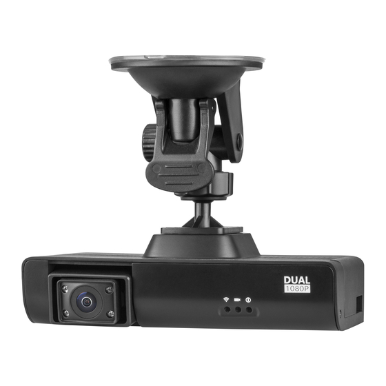
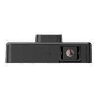
VIA Technologies Mobile360 D700 User Manual (38 pages)
Dual 1080p AI Dash Cam with CAN bus and 4G connectivity for fleet management
Brand:
VIA Technologies
| Category:
Dash Cameras
| Size: 2 MB
Table of Contents
Table of Contents
5
1 Product Overview
8
Key Features
8
Dual 1080P Front Dash and Interior Cameras
8
Networking Support
8
Cloud Integration
8
Storage Expansion
8
Embedded Operating App
8
Product Specifications
9
Layout Diagram
11
Figure 1: Front Panel I/O Layout
11
Figure 2: Rear Panel I/O Layout
11
Figure 3: Left Panel I/O Layout
11
Figure 4: Right Panel I/O Layout
12
Figure 5: Bottom Panel I/O Layout
12
Product Dimensions
13
Figure 6: Dimensions Of The Via Mobile360 D700 (Front View)
13
Figure 7: Dimensions Of The Via Mobile360 D700 (Top View)
13
2 External I/O Pin Descriptions and Functionality
14
Micro USB 2.0 Port
14
Micro SD Card Slot
14
Figure 8: Micro USB 2.0 Port Diagram
14
Figure 9: Micro SD Card Slot Diagram
14
Table 1: Micro USB 2.0 Port Pinouts
14
Table 2: Micro SD Card Slot Pinouts
14
Micro SIM Card Slot
15
12-Pin Power Connector
15
Figure 10: Micro SIM Card Slot Diagram
15
Figure 11: 12-Pin Power Connector Diagram
15
Table 3: Micro SIM Card Slot Pinouts
15
Table 4: 12-Pin Power Connector Pinouts
15
LED Status
16
Short Record / Alert Button
16
Figure 12: LED Indicators States Diagram
16
Figure 13: Short Record / Alert Button Diagram
16
Speaker
17
Microphone
17
Figure 14: Speaker Diagram
17
Figure 15: Microphone Diagram
17
3 Accessories
18
OBD II Power Cable
18
Cigarette Lighter Power Cable
18
Blade Fuse Holder Cables and Fuses
18
Figure 16: OBD II Power Cable Diagram
18
Figure 17: Cigarette Lighter Power Cable Diagram
18
Figure 18: Blade Fuse Holder Cables and Fuses Diagram
18
12-Pin Power Connector to DC Jack Combo Cable
19
DC Power Adaptor and Power Cord
19
Suction Cup and Adhesive Tape Mounting Brackets
19
Figure 19: 12-Pin Power Cable Connector to DC Jack Combo Cable Diagram
19
Figure 20: 12V DC Power Adaptor
19
Figure 21: Suction Cup And Adhesive Tape Mounting Brackets Diagram
19
4 VIA Mobile360 D700 Installation
20
Removing the Right Panel I/O Cover
20
Figure 22: Loosen the Screw of the Right Panel I/O Cover
20
Figure 23: Removing the Right Panel I/O Cover
20
Installing the Micro SD Card
21
Figure 24: Locating The Micro Sd Card Slot
21
Installing the 4G Micro SIM Card
22
Figure 25: Locating The Micro Sim Card Slot
22
Installing the Cables
23
Using the Cigarette Lighter Power Cable
23
Figure 27: Plugging In The 12-Pin Connector Of The Cigarette Lighter Power Cable
23
Figure 26: Feeding the 12-Pin Connector Cable through the Hole on the I/O Cover
23
Figure 29: Inserting The Cigarette Lighter Power Cable To The Vehicle
24
Figure 28: Reinstalling the Right Panel I/O Cover
24
Cigarette Lighter Cable Connections Diagram
25
Figure 30: Cigarette Lighter Power Cable's Connectors
25
Figure 31: Cigarette Lighter Cable Connections
25
Table 5: Cigarette Lighter Power Cable's Connectors Pinouts
25
Using the OBD II Power Cable
26
Figure 32: Vehicle's Fuse Box
26
Figure 33: Extracting The Acc Fuse From The Fuse Box
26
Figure 34: Installing The Acc Fuses On The Blade Fuse Holder Cable
27
Figure 35: Connecting The Blade Fuse Holder Cable To The Fuse Box
27
Figure 36: Feeding the 12-Pin Connector Cable through the Hole on the I/O Cover
28
Figure 37: Plugging in the 12-Pin Connector of the OBD II Power Cable
28
Figure 38: Reinstalling the Right Panel I/O Cover
28
Figure 39: Connecting The Obd II Power Cable To The Blade Fuse Holder Cable
29
Figure 40: Plugging in the OBD II Power Cable to the OBD II Connector
29
Figure 41: Obd II Power Cable's Connectors
30
Table 6: OBD II Power Cable's Connectors Pinouts
30
Figure 42: Obd II Power Cable Connections
31
OBD II Power Cable Connections Diagram
31
Using 12-Pin Power Connector to DC Jack Combo Cable
32
Figure 43: Feeding the 12-Pin Connector through the Hole on the I/O Cover
32
Figure 44: Plugging in the 12-Pin Connector of the 12-Pin Power Connector to DC Jack Combo Cable
32
Figure 45: Reinstalling the Right Panel I/O Cover
33
Figure 46: Plugging in the 12V DC Power Adaptor to the 12-Pin Power Connector to DC Jack Combo Cable
33
Figure 47: 12-Pin Power Connector To DC Jack Combo Cable's Connectors
34
Figure 48: Acc Simulator Switch
34
Table 7: 12-Pin Power Connector to DC Jack Combo Cable's Connectors Pinouts
34
12-Pin Power Connector to DC Jack Combo Cable Connections Diagram
35
Figure 49: 12-Pin Power Connector To DC Jack Combo Cable Connections
35
Mounting the VIA Mobile360 D700
36
Figure 50: Installing The Mounting Bracket On The Via Mobile360 D700
36
Figure 51: Mounting The Via Mobile360 D700
36
5 Technical Support
37
Technical Support and Assistance
37
Advertisement
VIA Technologies Mobile360 D700 User Manual (36 pages)
Powerful and feature-rich AI dash cam for commercial-grade fleet management applications
Brand:
VIA Technologies
| Category:
Dash Cameras
| Size: 2 MB
Table of Contents
Table of Contents
5
Product Overview
9
Key Features
9
Dual 1080P Front Dash and Interior Cameras
9
Networking Support
9
Cloud Integration
9
Storage Expansion
9
Reference App
9
Product Specifications
10
Layout Diagram
11
Figure 01: Front Panel I/O Layout
11
Figure 02: Rear Panel I/O Layout
12
Figure 03: Left Panel I/O Layout
12
Figure 04: Right Panel I/O Layout
12
Product Dimensions
13
Figure 05: Bottom Panel I/O Layout
13
Figure 06: Dimensions of the VIA Mobile360 D700 (Front View)
13
Figure 07: Dimensions of the VIA Mobile360 D700 (Top View)
13
External I/O Pin Descriptions and Functionality
14
Micro USB 2.0 Port
14
Microsd Card Slot
14
Figure 08: Micro USB 2.0 Port Diagram
14
Figure 09: Microsd Card Slot Diagram
14
Table 01: Micro USB 2.0 Port Pinouts
14
Table 02: Microsd Card Slot Pinouts
14
Micro SIM Card Slot
15
12-Pin Power Connector
15
Figure 10: Micro SIM Card Slot Diagram
15
Figure 11: 12-Pin Power Connector Diagram
15
Table 03: Micro SIM Card Slot Pinouts
15
Table 04: 12-Pin Power Connector Pinouts
15
LED Status
16
Short Record / Two-Way Call Button
16
Figure 12: LED Indicators States Diagram
16
Figure 13: Short Record / Two-Way Call Button Diagram
16
Speaker
17
Microphone
17
Figure 14: Speaker Diagram
17
Figure 15: Microphone Diagram
17
Accessories
18
OBD II Power Cable
18
Blade Fuse Holder Cables and Fuses
18
Figure 16: OBD II Power Cable Diagram
18
Figure 17: Blade Fuse Holder Cables and Fuses Diagram12-Pin Power Connector to DC Jack Combo Cable
18
Figure 18: 12-Pin Power Cable Connector to DC Jack Combo Cable Diagram
18
DC Power Adaptor and Power Cord
19
Suction Cup and Adhesive Tape Mounting Brackets
19
Figure 19: 12V DC Power Adaptor
19
Figure 20: Suction Cup and Adhesive Tape Mounting Brackets Diagram
19
VIA Mobile360 D700 Installation
20
Removing the Right Panel I/O Cover
20
Installing the Microsd Card
20
Figure 21: Loosen the Screw of the Right Panel I/O Cover
20
Figure 22: Removing the Right Panel I/O Cover
20
Installing the 4G Micro SIM Card
21
Figure 23: Locating the Microsd Card Slot
21
Figure 24: Locating the Micro SIM Card Slot
21
Installing the Power/Acc Cable
22
Installing the OBD II Power Cable
22
Figure 25: OBD II Power Cable Connections
22
Figure 26: Vehicle's Fuse Box
22
Figure 27: Extracting the ACC Fuse from the Fuse Box
23
Figure 28: Installing the ACC Fuses on the Blade Fuse Holder Cable
23
Figure 29: Connecting the Blade Fuse Holder Cable to the Fuse Box
24
Figure 30: Feeding the 12-Pin Connector Cable through the Hole in the I/O Cover
24
Figure 31: Plugging in the 12-Pin Connector of the OBD II Power Cable
25
Figure 32: Reinstalling the Right Panel I/O Cover
25
Figure 33: Connecting the OBD II Power Cable to the Blade Fuse Holder Cable
26
Figure 34: Inserting the OBD II Power Cable to the OBD II Connector
26
Figure 35: OBD II Power Cable Connector Pinouts
27
Table 05: OBD II Power Cable Connector Pinouts
27
Installing the 12-Pin Power Connector to DC Jack Combo Cable
28
Figure 36: 12-Pin Power Connector to DC Jack Combo Cable Connections
28
Figure 37: Feeding the 12-Pin Connector through the Hole on the I/O Cover
28
Figure 38: Plugging in the 12-Pin Connector of the 12-Pin Power Connector to DC Jack Combo Cable
29
Figure 39: Reinstalling the Right Panel I/O Cover
29
Figure 40: Plugging in the 12V DC Power Adaptor to the 12-Pin Power Connector to DC Jack Combo Cable
30
Figure 41: ACC Simulator Switch
30
Figure 42: 12-Pin Power Connector to DC Jack Combo Cable's Connectors
30
Mounting the VIA Mobile360 D700
31
Adhesive Tape Mounting Bracket Installation
31
Figure 43: Mobile360 Mounting Brackets
31
Table 06: 12-Pin Power Connector to DC Jack Combo Cable's Connectors Pinouts
31
Figure 44: Install the Adhesive Tape Mounting Bracket
32
Figure 45: Installing the Adhesive Tape Mounting Bracket on the VIA Mobile360 D700
32
Suction Cup Mounting Bracket Installation
33
Figure 46: Assembly the Suction Cup Bracket
33
Figure 47: Mounting the Suction Cup Bracket on the Windshield
33
Figure 48: Suction Cup Mounting Bracket Lever
34
Figure 49: Installing the Mounting Bracket on the VIA Mobile360 D700
34
Technical Support
35
Technical Support and Assistance
35
VIA Technologies Mobile360 D700 Quick Start Manual (60 pages)
EVK
Brand:
VIA Technologies
| Category:
Dash Cameras
| Size: 5 MB
Table of Contents
Table of Contents
4
Via Mobile360 D700 Introduction
6
EVK Package Content
6
Document Folder Content
6
1�1�2 Firmware Folder Content
6
2� Upgrade Firmware Using SD Card
7
LED Status
8
3� VIA Fleet Cloud Management Portal
9
System Prerequisites
9
VIA Fleet Login and Overview
9
3�2�1 Login
9
3�2�2 VIA Fleet Overview
10
Setting up the Test Environment
11
Via Fleet Vehicle Registration
11
Via Mobile360 D700 Device Registration
15
3�3�3 Enabling AI Features
19
Installation With Ai Features
20
Dms Calibration
22
Adas Calibration
23
3�3�3�4 Select Features
26
Via Fleet Driver Registration
27
Registering A Driver For A Trip
29
Account Settings
31
3�4�1 My Account
31
System Settings
32
Live Tracking
33
Collision Alert Notification
36
2-Way Calling Notifications
37
Dashboard
39
Trip History
41
3�9�1 Driver
41
3�9�2 Alerts
45
3�10 Management
46
Vehicles
46
Registration Status And Trial Period Information
47
Deleting And Editing Fleets And Vehicles
48
3�10�4 Drivers
49
4� VIA Mobile360 App
50
Connecting to VIA Mobile360 D700
50
App Menu
51
Live
52
Device Settings
53
Trips
55
Stats
56
Album
57
Advertisement
VIA Technologies Mobile360 D700 Quick Start Manual (39 pages)
Brand:
VIA Technologies
| Category:
Dash Cameras
| Size: 2 MB
Table of Contents
Table of Contents
4
VIA Mobile360 D700 Introduction
5
EVK Package Content
5
Document Folder Content
5
Firmware Folder Content
5
Upgrade Firmware Using SD Card
6
System Status Leds
7
VIA Fleet Cloud Management Portal
8
VIA Fleet Vehicle Registration
8
VIA Mobile360 D700 Device Registration
12
ADAS and DSS AI Features
17
Installation with AI Features
18
ADAS Calibration
20
DSS Calibration
22
Device Settings
25
VIA Mobile360 App
27
Connecting to VIA Mobile360 D700
28
App Menu
29
Live
30
Device Settings
31
Trips
34
Stats
35
Album
36
VIA Technologies Mobile360 D700 User Manual (24 pages)
Brand:
VIA Technologies
| Category:
Automobile Electronics
| Size: 0 MB
Advertisement
Related Products
VIA Technologies Mobile360 M820
VIA Technologies Mobile360 M810
VIA Technologies Mobile360 L900
VIA Technologies Mobile360 M500
VIA Technologies Mobile360 FSS
VIA Technologies Mobile360 M800
VIA Technologies M3N78
VIA Technologies EPIA ME6000 - VIA Motherboard - Mini ITX
VIA Technologies Mini-ITX Mainboard EPIA-MII
VIA Technologies M2N68-VM - Motherboard - Micro ATX
VIA Technologies Categories
Motherboard
Computer Hardware
Desktop
Control Unit
Industrial PC
More VIA Technologies Manuals
Login
Sign In
OR
Sign in with Facebook
Sign in with Google
Upload manual
Upload from disk
Upload from URL