Sign In
Upload
Manuals
Brands
VIA Technologies Manuals
Automobile Accessories
Mobile360 M820
VIA Technologies Mobile360 M820 Manuals
Manuals and User Guides for VIA Technologies Mobile360 M820. We have
2
VIA Technologies Mobile360 M820 manuals available for free PDF download: User Manual
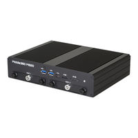
VIA Technologies Mobile360 M820 User Manual (53 pages)
Fanless ultra-compact in-vehicle safety system with flexible ADAS, SVS, and DMS integration options
Brand:
VIA Technologies
| Category:
Automobile Accessories
| Size: 2 MB
Table of Contents
Table of Contents
6
1 Product Overview
11
Key Features
11
High-Performance
11
Fanless, Compact, Ruggedized Chassis
11
Optimized Integration with Multiple I/O Access
11
Multiple Camera Support
11
Support for a Wide Range of Power Sources
11
Storage Expansion
12
Networking Support
12
Mounting Solution
12
Embedded Operating System Ready
12
Product Specifications
12
Layout Diagram
14
Figure 01: Front Panel I/O Layout
14
Figure 02: Back Panel I/O Layout
15
Figure 03: Dimensions of the VIA Mobile360 M820 (Front View)
15
Figure 04: Dimensions of the VIA Mobile360 M820 (Side View)
15
Figure 05: Dimensions of the VIA Mobile360 M820 (Bottom View)
16
2 External I/O Pin Descriptions and Functionality
17
HDMI Port
17
USB 3.0 Ports
17
Micro USB 2.0 Port
17
Figure 06: HDMI Port Diagram
17
Figure 07: USB 3.0 Port Diagram
17
Table 01: HDMI Port Pinouts
17
Table 02: USB 3.0 Port Pinouts
17
Gigabit Ethernet Port
18
Micro SD Card Slot
18
Figure 08: Micro USB 2.0 Port Diagram
18
Figure 09: Gigabit Ethernet Port Diagram
18
Table 03: Micro SD Card Slot Pinouts
18
Table 04: Gigabit Ethernet Port Pinouts
18
Table 05: Gigabit Ethernet Port LED Color Definition
18
SIM Card Slot
19
Figure 10: Micro SD Card Slot Diagram
19
Figure 11: SIM Card Slot Diagram
19
Table 06: SIM Card Slot Pinouts
19
Table 07: SIM Card Slot Pinouts
19
DIO Port
20
Headphone and MIC-In Port
20
COM Port
20
Figure 12: DIO Port Diagram
20
Figure 13: Headphone and MIC-In Port Diagram
20
Figure 14: COM Port Diagram
20
Table 08: DIO Port Pinouts
20
Table 09: Headphone and MIC-In Port Pinouts
20
Table 10: COM Port Pinouts
20
CAN Bus Port
21
FAKRA Connectors
21
Power Button
21
Figure 15: CAN Bus Port Diagram
21
Figure 16: FAKRA Connector Diagram
21
Figure 17: Power Button Diagram
21
Table 11: CAN Bus Ports Pinouts
21
Table 12: FAKRA Connector Pinout
21
DC-In Jack
22
DC-Out Jack
22
Figure 18: DC-In Jack Diagram
22
Figure 19: DC-Out Jack Diagram
22
Table 13: Power Button Behavior Description
22
Table 14: Power Button Behavior Description
22
Table 15: DC-Out Jack Pinouts
22
Antenna Connectors
23
Figure 20: Wi-Fi Antenna Connectors Diagram
23
Figure 21: GPS and 4G Antenna Connectors Diagram
23
3 Onboard I/O
24
Minipcie Slot
24
Figure 22: Minipcie Slot Diagram
24
Table 16: Minipcie Slot Pinouts
24
4 Hardware Installation
25
Installing the 2.5" SATA HDD/SSD
25
Figure 23: Unlocking the SATA HDD/SSD Bay
25
Figure 24: Removing the SATA HDD/SSD Bays
25
Figure 25: Installing the 2.5" SATA HDD/SSD
26
Figure 26: Reinstalling the SATA HDD/SSD Bays
26
Installing the Wi-Fi Antennas
27
Installing the GPS Antenna
27
Figure 27: Installing the Wi-Fi Antennas
27
Figure 28: Installing the GPS Antenna
27
Installing the FOV Cameras and FAKRA Cables
28
Figure 29: Connecting the FOV Camera to the FAKRA Cable
28
Figure 30: Connecting the FAKRA Cable to the FAKRA Connector
28
Unplugging the FAKRA Cable
29
Figure 31: Unplugging the FAKRA Cable
29
Connecting the VIA Mobile360 M820 to the Vehicle's Ignition (IGN)
30
Figure 32: DIO Port's Pin 8
30
Figure 33: VIA Mobile360 M820 and IGN Connection Method Diagram
30
Installing the Phoenix Plug to DC Jack
31
Figure 34: Connecting the Battery Cables Onto the Phoenix Plug to DC Jack
31
Figure 35: Connecting the Phoenix Plug to DC Jack
31
5 Software and Technical Support
32
Yocto Support
32
Technical Support and Assistance
32
Appendix A Installing Wireless Accessories
33
Installing the Mobile Broadband Minipcie Module
33
Figure 36: Unscrewing the Bottom Plate Cover
33
Figure 37: Removing the Bottom Plate Cover
34
Figure 38: Installing the Mobile Broadband Module
34
Figure 39: Connecting the 4G Antenna Cable to the Micro-RF Connector on the Module
35
Figure 40: Installing the 4G Antenna
35
Appendix B Installing Automotive-Grade Cameras to the Camera Brackets
36
Installing the FOV-190 Automotive-Grade Camera to the Camera Bracket
36
Figure 41: Attaching the Internal Bracket to the External Bracket
36
Figure 42: Installing the Double-Sided Adhesive Tape on the Camera Bracket
36
Figure 43: Installing the FOV-190 Camera on the Camera Bracket
37
Figure 44: Removing the Double-Sided Adhesive Tape Protective Cover
37
Figure 45: Installing the Camera Bracket with FOV-190 Camera on Your Vehicle
38
Figure 46: Adjusting the FOV-190 Camera Angle
38
Installing the FOV-35 Automotive-Grade Camera to the Camera Bracket
39
Figure 47: Attaching the Internal Bracket to the External Bracket
39
Figure 48: Installing the Double-Sided Adhesive Tape on the Camera Bracket
39
Figure 49: Preparing the FOV-35 Camera
40
Figure 50: Installing the FOV-35 Camera on the Camera Bracket
40
Figure 51: Removing the Double-Sided Adhesive Tape Protective Cover
41
Figure 52: Installing the Camera Bracket with FOV-35 Camera on Your Vehicle
42
Installing the Front ADAS Automotive-Grade Camera
43
Figure 53: Adjusting the FOV-35 Camera Angle
43
Figure 54: Removing the Protective Lens Cover
44
Figure 55: Installing the Front ADAS Camera
44
Figure 56: Adjusting the Front ADAS Camera Angle
45
Figure 57: Connecting the Power and Microphone/Speaker Adapter Cable
45
Figure 58: Connecting the 2-Pole Power Connector for the Front ADAS Camera
46
Figure 59: Connecting the HP/MIC/GND Wires for the Front ADAS Camera
46
Installing the DMS Automotive-Grade Camera
47
Figure 60: Removing the Double-Sided Adhesive Tape Protective Cover
47
Figure 61: Installing the DMS Camera in Your Vehicle
48
Figure 62: Adjusting the DMS Camera Angle
48
Figure 63: Connecting the USB Power Adapter Cable
49
Figure 64: Connecting the USB Cable to the VIA Mobile360 M820
49
Appendix C Installing Mounting Bracket
50
Figure 65: Mounting Bracket Parts
50
Figure 66: Installing the VIA Mobile360 M820 Onto the Top Casing
50
Figure 67: Installing the Base Cover
51
Figure 68: Securing the Top Casing and Base Cover Together
51
Figure 69: Mounting the VIA Mobile360 M820
52
Advertisement
VIA Technologies Mobile360 M820 User Manual (46 pages)
Fanless ultra-compact in-vehicle 360 C surround view surveillance & ADAS system
Brand:
VIA Technologies
| Category:
Automobile Accessories
| Size: 9 MB
Table of Contents
Table of Contents
5
1 Product Overview
10
Key Features
10
High-Performance
10
Fanless, Compact, Ruggedized Chassis
10
Optimized Integration with Multiple I/O Access
10
Multiple Camera Support
10
Support for a Wide Range of Power Sources
10
Storage Expansion
11
Networking Support
11
Mounting Solution
11
Embedded Operating System Ready
11
Product Specifications
12
Layout Diagram
14
Figure 1: Front Panel I/O Layout
14
Figure 2: Back Panel I/O Layout
14
Product Dimensions
15
Figure 3: Dimensions Of The Via Mobile360 M820 (Front View)
15
Figure 4: Dimensions Of The Via Mobile360 M820 (Side View)
15
Figure 5: Dimensions Of The Via Mobile360 M820 (Bottom View)
15
2 External I/O Pin Descriptions And Functionality
16
HDMI ® Port
16
USB 3.0 Ports
16
Figure 6: Hdmi Port Diagram
16
Figure 7: Usb 3.0 Port Diagram
16
Table 1: HDMI Port Pinouts
16
Table 2: USB 3.0 Pinouts
16
Micro USB 2.0 Port
17
Gigabit Ethernet Port
17
Figure 8: Micro Usb 2.0 Port Diagram
17
Figure 9: Gigabit Ethernet Port Diagram
17
Table 3: Micro USB 2.0 Port Pinouts
17
Table 4: Gigabit Ethernet Port Pinouts
17
Table 5: Gigabit Ethernet Port LED Color Definition
17
Micro SD Card Slot
18
SIM Card Slot
18
Figure 10: Micro Sd Card Slot Diagram
18
Figure 11: Sim Card Slot Diagram
18
Table 6: Micro SD Card Slot Pinouts
18
Table 7: SIM Card Slot Pinouts
18
DIO Port
19
Headphone and MIC-In Port
19
COM Port
19
Figure 12: Dio Port Diagram
19
Figure 13: Headphone And MIC-In Port Diagram
19
Figure 14: Com Port Diagram
19
Table 8: DIO Port Pinouts
19
Table 9: Headphone and MIC-In Port Pinouts
19
Table 10: Com Port Pinouts
19
Can Bus Port
20
Fakra Connectors
20
Figure 15: Can Bus Port Diagram
20
Figure 16: Fakra Connector Diagram
20
Table 11: Can Bus Port Pinouts
20
Table 12: Fakra Connector Pinouts
20
Power Button
21
DC-In Jack
21
DC-Out Jack
21
Figure 17: Power Button Diagram
21
Figure 18: DC-In Jack Diagram
21
Figure 19: DC-Out Jack Diagram
21
Table 13: Power Button Behavior Description
21
Table 14: DC-In Jack Pinouts
21
Table 15: DC-Out Jack Pinouts
21
Antenna Connectors
22
Figure 20: Wi-Fi Antenna Connectors Diagram
22
Figure 21: 4G And Gps Antenna Connectors Diagram
22
3 Onboard I/O
23
Minipcie Slot
23
Figure 22: Minipcie Slot Diagram
23
Table 16: Minipcie Slot Pinouts
23
4 Hardware Installation
24
Installing the 2.5" SATA HDD/SSD
24
Figure 23: Unlocking The Sata Hdd/Ssd Bay
24
Figure 24: Removing The Sata Hdd/Ssd Bays
24
Figure 25: Installing The 2.5" Sata Hdd/Ssd
25
Figure 26: Reinstalling The Sata Hdd/Ssd Bays
25
Installing the Wi-Fi Antennas
26
Installing the GPS Antenna
26
Figure 27: Installing The Wi-Fi Antennas
26
Figure 28: Installing The Gps Antenna
26
Installing the FOV Cameras and FAKRA Cables
27
Figure 29: Connecting The Fov Camera To The Fakra Cable
27
Figure 30: Connecting The Fakra Cable To The Fakra Connector
27
Unplugging the FAKRA Cable
28
Figure 31: Uplugging The Fakra Cable
28
Connecting VIA Mobile360 M820 to the Vehicle's Ignition (IGN)
29
Figure 32: Gpio Port's Pin 8
29
Figure 33: Via Mobile360 M820 And Ign Connection Method Diagram
29
Installing the Phoenix Plug to DC Jack
30
Figure 34: Connecting The Battery Cables Onto The Phoenix Plug To DC Jack
30
Figure 35: Connecting The Phoenix Plug To DC Jack
30
5 Software And Technical Support
31
Android Support
31
Technical Support and Assistance
31
Appendix A. Installing Wireless Accessories
32
Installing The Mobile Broadband Minipcie Module
32
Figure 36: Unscrewing The Bottom Plate Cover
32
Figure 37: Removing The Bottom Plate Cover
33
Figure 38: Installing The Mobile Broadband Module
33
Figure 39: Connecting The 4G Antenna Cable To The Micro-Rf Connector On The Module
34
Figure 40: Installing The 4G Antenna
34
Appendix B. Installing Mounting Bracket
35
Installing The Mounting Bracket
35
Figure 41: Installing The Rubber Dampers
35
Figure 42: Installing The Mounting Bracket
36
Figure 43: Securing The Mounting Bracket
37
Appendix C. Installing VIA Mobile360 M820
38
Mounting The Via Mobile360 M820
38
Figure 44: Mounting The Via Mobile360 M820
38
Appendix D. Installing FOV Automotive-Grade Cameras to the Camera Brackets
39
Installing The Fov-190 Automotive-Grade Camera To The Svs Camera Bracket
39
Figure 45: Installing The Fov-190 Automotive-Grade Camera On The Internal Bracket (Svs Camera Bracket)
39
Figure 46: Attaching The Internal Bracket To The External Bracket (Svs Camera Bracket)
39
Figure 47: Installing The Double-Sided Adhesive Tape On The External Bracket (Svs Camera Bracket)
40
Figure 48: Removing The Double-Sided Adhesive Tape Protective Cover (Svs Camera Bracket)
40
Installing The Fov-40 Automotive-Grade Camera To The Bsd Camera Bracket
41
Figure 49: Installing The Fov-40 Automotive-Grade Camera On The Internal Bracket (Bsd Camera Bracket)
41
Figure 50: Attaching The Internal Bracket To The External Bracket (Bsd Camera Bracket)
41
Figure 51: Installing The Double-Sided Adhesive Tape On The External Bracket (Bsd Camera Bracket)
42
Figure 52: Removing The Double-Sided Adhesive Tape Protective Cover (Bsd Camera Bracket)
42
Installing The Fov-40 Automotive-Grade Camera To The Fcw Camera Bracket
43
Figure 53: Installing The Fov-40 Automotive-Grade Camera On The Internal Bracket (Fcw Camera Bracket)
43
Figure 54: Attaching The Internal Bracket To The External Bracket (Fcw Camera Bracket)
43
Figure 55: Attaching The Rotate-Base Plate To The External Bracket (Fcw Camera Bracket)
44
Advertisement
Related Products
VIA Technologies Mobile360 D700
VIA Technologies Mobile360 M810
VIA Technologies Mobile360 L900
VIA Technologies Mobile360 M500
VIA Technologies Mobile360 FSS
VIA Technologies Mobile360 M800
VIA Technologies M2N-CM DVI
VIA Technologies M3A78 - Motherboard - ATX
VIA Technologies Mini-ITX
VIA Technologies M3N78-VM - Motherboard - Micro ATX
VIA Technologies Categories
Motherboard
Computer Hardware
Desktop
Control Unit
Industrial PC
More VIA Technologies Manuals
Login
Sign In
OR
Sign in with Facebook
Sign in with Google
Upload manual
Upload from disk
Upload from URL