Sign In
Upload
Manuals
Brands
VIA Technologies Manuals
Safety Equipment
Mobile360 M500
VIA Technologies Mobile360 M500 Manuals
Manuals and User Guides for VIA Technologies Mobile360 M500. We have
2
VIA Technologies Mobile360 M500 manuals available for free PDF download: Installation Manual
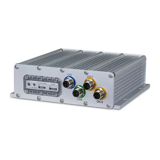
VIA Technologies Mobile360 M500 Installation Manual (128 pages)
Forklift Safety System, 3 Camera People Detection
Brand:
VIA Technologies
| Category:
Safety Equipment
| Size: 23 MB
Table of Contents
Table of Contents
9
Product Overview
15
System Layout
15
Figure 01: Front Panel I/O Layout
15
System Dimensions
16
Figure 02: Rear Panel I/O Layout
16
Figure 03: Front View System Dimensions
16
Figure 04: Side View System Dimensions
16
Installation
17
System Preparation
17
Inserting a Microsd Card
17
Table 01: Microsd Card Recording Times
17
Inserting a Micro SIM Card
18
Securing the Waterproof Cover
18
Figure 05: Inserting a Microsd and a Micro SIM Card
18
Figure 06: Securing the Waterproof Cover
18
Attaching the I/O Covers
19
Figure 07: Covering Unused Front Panel Ports
19
Figure 08: Covering Unused Rear Panel Ports
19
Attaching the Vibration Dampening Strips
20
Figure 09: Vibration Dampening Strip Installation
20
VIA Mobile360 M500 System Installation
21
Figure 10: Recommended Installation Space Requirements
21
Figure 11: Recommended Installation Locations
21
Camera Installation
22
Figure 12: Camera Installation Height Range
22
Figure 13: Left-Right-Rear Camera Installation Locations
23
Figure 14: Scenario a Left-Right-Rear Camera Installation
23
Table 02: Maximum Sides-To-Rear Camera Distances
23
Figure 15: Scenario B Left-Right-Rear Camera Installation
24
Figure 16: Two-Front-One-Rear Camera Installation
24
Attaching the Cameras
25
Figure 17: One-Front-Two-Rear Camera Installation
25
Figure 18: Attaching Magnets and 3M Tape to Cameras
25
Figure 19: Marking Installation Location and Drilling
26
Figure 20: Marking the Installation Location for a Side Camera to be Rotated 30° Towards the Rear
26
Speaker Installation
27
Figure 21: Installing Cameras with Molly Bolts
27
Figure 22: Speaker Installation
27
Wi-Fi/Gps Antenna Installation
28
Figure 23: Wi-Fi/Gps Antenna Installation
28
LTE Antenna Installation
29
Figure 24: 4G LTE Antenna Module Protective 3M Tape Cover Removal
29
Peripheral Cabling and Connection
30
Figure 25: Applying LOCTITE 243 Threadlocker to I/O Ports
30
Figure 26: Front I/O Cable Connections
30
Connecting Ground, ACC and Power
31
Figure 27: Rear I/O Cable Connections
31
Figure 28: M12 Power Cable
32
Figure 29: Blade Fuse Holder Cables
32
Turning System On/Off
35
Table 03: System LED Status
35
System Reset
36
Figure 30: System Reset
36
Safety Alerts & Camera Calibration
37
Camera Alerts
37
Figure 31: Mode A: People Detection Zone Coverage
37
Figure 32: Mode B: People Detection Zone Coverage
38
Figure 33: Mode C: People Detection Zone Coverage
39
Table 04: People Detection Alert Logic Based on Speed Threshold
40
Table 05: People Detection Audio Alerts
40
Camera Calibration
41
Table 06: Speed Limit Reference
43
Figure 34: Camera Calibration Pattern Placement
44
Figure 35: Camera Angle Adjustment
45
Figure 36: Mode A: Narrowing the Range of the Left and Right Cameras' Detection Zones
47
Figure 37: Mode B: Narrowing the Range of All Cameras' Detection Zones
48
Figure 38: Mode C: Narrowing the Range of All Cameras' Detection Zones
48
VIA Workx Connect App
52
Connecting the VIA Workx Connect App
52
Upgrading System Firmware
53
App Menu
54
Camera Calibration
55
Settings
56
Album
58
Info
60
Appendix A Optional Accessories
63
7" CVBS Display Kit
63
Table 07: 7" CVBS Display Specifications
63
Package Contents
64
Figure 39: 7" CVBS Display Kit
64
Display Buttons
65
Figure 40: 7" CVBS Display Buttons
65
Installation
66
Figure 41: Mounting Plate Fixing Holes
66
Figure 42: Finding a Suitable Installation Location for the CVBS Display
66
Figure 43: Determine Four Screw Holes Suitable to Fix the Hinge on the Mounting Plate
67
Figure 44: Mark Hole Positions to Mount Hinge and Mounting Plate
67
Figure 45: Distance between Drill Holes
68
Figure 46: Affix the Magnet Mounting Plate on the Mounting Plate
68
Figure 47: Affix the Magnet on the Magnet Mounting Plate
69
Figure 48: Affix Rubber Pads on the Magnet
69
Figure 49: Drill Holes into the A-Pillar and Insert Molly Bolts
70
Figure 50: Affix the Mounting Plate on the A-Pillar
70
Figure 51: Affix the Hinge on the Mounting Plate
71
Figure 52: Align the CVBS Display Fixed Bracket with the Hinge
71
Figure 53: Affix the CVBS Display Fixed Bracket on the Hinge
72
Figure 54: Adjust the Display Viewing Angle by Pushing Left/Right or Up/Down
72
Figure 55: Adjust the Display Viewing Angle by Rotating Left/Right
73
Figure 56: Tighten Screws Holding the Display Panel to the Hinge
73
Figure 57: 7" CVBS Display Cable Connections
74
Display Interface
75
Figure 58: Modes a and B: 3 Camera View
75
Figure 59: Mode C: 3 Camera View
75
Figure 60: Mode A: Full-Screen Rear Camera View
76
Figure 61: Mode B: Full-Screen Rear Camera View
76
Figure 62: Mode C: Full-Screen Front Camera View
77
Table 08: 7" CVBS Panel Alert Icons
77
NFC Card Reader
78
Package Contents
78
Installation
78
Figure 63: the NFC Card Reader
78
Figure 64: NFC Card Reader Cable Connection
79
DIO2 Cable
80
Figure 65: DIO2 Cable
80
Table 09: DIO2 Cable Bullet Head Connectors Specifications
80
Figure 66: DIO2 Cable Installation
81
Wireless Speed Sensor Kit
83
Package Contents
83
Installation
83
Figure 67: Select a Suitable Wireless Speed Sensor Mounting Bracket
83
Figure 68: Insert the Wireless Speed Sensor Module into the Mounting Bracket
83
Figure 69: Install the Wireless Speed Sensor Mounting Bracket on the Tire
84
Selecting the Display Layout
86
Figure 70: Modes a and B: 3 Camera View and Speed Reading
86
Figure 71: Mode C: 3 Camera View and Speed Reading
87
Figure 72: Mode A: Full-Screen Rear Camera View and Speed Reading
87
Figure 73: Mode B: Full-Screen Rear Camera View and Speed Reading
88
Figure 74: Mode C: Full-Screen Front Camera View and Speed Reading
88
Selecting the Alert Direction
89
Replacing the Battery
89
Table 10: Battery Lifespan Based on Average Operating Hours Per Week
89
Figure 75: 3 Camera View and Wireless Speed Sensor Battery Status
90
Figure 76: Remove the Wireless Speed Sensor Mounting Bracket from the Tire
90
Figure 77: Extract the Wireless Speed Sensor from the Mounting Bracket
91
Figure 78: Open the Sensor Module's Casing and Remove the Circuit Board from the Top Casing
91
Figure 79: Replace the Battery and Insert the Circuit Board Back into the Top Casing
92
Figure 80: Placing the Wireless Speed Sensor's Bottom Casing on Its Top Casing
92
Figure 81: Securing the Wireless Speed Sensor's Bottom Casing and Top Casing
92
Figure 82: Insert the Wireless Speed Sensor Module into the Mounting Bracket
93
Figure 83: Install the Wireless Speed Sensor Mounting Bracket on the Tire
93
Unpairing the Wireless Speed Sensor
94
Speed and Reverse Light Sensor Kit
95
Package Contents
95
Installation
95
Speed Sensor Installation
95
Figure 84: Speed and Reverse Light Sensor Kit
95
Figure 85: Assembling the Speed Sensor and Mounting Bracket
96
Figure 86: Speed Sensor Installation
96
Reverse Light Sensor Installation
97
Connecting Sensors to VIA Mobile360 M500 System
97
Figure 87: Attaching the Reverse Light Sensor to Forklift's Reverse Light
97
Sensor Configuration
98
Speed Sensor Configuration
98
Figure 88: Connecting Sensors to the VIA Mobile360 M500 System
98
Reverse Light Sensor Configuration
100
Figure 89: Removing the M3 Screw on the Light Sensor's Sensitivity Control Box
100
Selecting the Display Layout
101
Figure 90: Modes a and B: 3 Camera View and Speed Reading
101
Figure 91: Mode C: 3 Camera View and Speed Reading
102
Figure 92: Mode A: Full-Screen Rear Camera View and Speed Reading
102
Figure 93: Mode B: Full-Screen Rear Camera View and Speed Reading
103
Figure 94: Mode C: Full-Screen Front Camera View and Speed Reading
103
Selecting the Alert Direction
104
Deactivating the Sensors
105
Seatbelt Sensor
106
Figure 95: Seatbelt Sensor Installation
106
Display Interface and Alerts
107
Table 11: Seatbelt Sensor Inputs with Display and Voice Alert
107
Replacing the Battery
108
Figure 96: 3-Camera View and Seatbelt Status on
108
Table 12: Battery Lifespan Based on Average Operating Hours Per Week
108
Figure 97: 3 Camera View and Seatbelt Sensor Battery Status
109
Figure 98: Open the Seatbelt Sensor Casing
109
Unpairing the Seatbelt Sensor
110
Figure 99: Replace the Battery
110
DC Power Module
111
Package Contents
111
Installation
111
Figure 100: DC Power Module
111
VESA Plates
115
Package Contents
115
Table 13: Contents in each VESA Plate Package
115
Installation
116
Figure 101: Install the System VESA Plate
116
Figure 102: Install a Camera VESA Plate
117
Figure 103: Install the CVBS Display VESA Plate
117
Figure 104: Install the Card Reader VESA Plate
118
Figure 105: Install the Power Module VESA Plate
118
RAM® Mounts Kit
119
Package Contents
119
Installation
119
Figure 106: Parts of the RAM® Mounts Kit
119
Table 14: RAM® Mounts Kit Package Contents
119
Figure 107: Example of a VESA Plate - RAM® Mount Assembly
120
Appendix B Troubleshooting
121
Advertisement
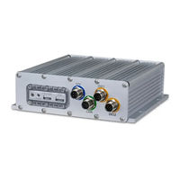
VIA Technologies Mobile360 M500 Installation Manual (49 pages)
Forklift Safety System
Brand:
VIA Technologies
| Category:
Safety Equipment
| Size: 3 MB
Table of Contents
Table of Contents
7
1 Product Overview
10
Packing Contents
10
System Layout
11
System Dimensions
11
Figure 01: Front Panel I/O Layout
11
Figure 02: Rear Panel I/O Layout
11
Figure 03: Front View System Dimensions
11
Figure 04: Side View System Dimensions
12
Figure 05: Bottom View System Dimensions - Removable Panel
12
2 Installation
13
System Preparation
13
Inserting a Microsd Card
13
Table 01: Microsd Card Recording Times
13
Securing the Waterproof Cover
14
Attaching the I/O Covers
14
Figure 06: Securing the Waterproof Cover
14
Figure 07: Covering Unused Front Panel Ports
14
Attaching the Vibration Dampening Strips
15
Figure 08: Covering Unused Rear Panel Ports
15
Figure 09: Vibration Dampening Strip Installation
15
VIA Mobile360 M500 System Installation
16
Figure 10: Recommend Installation Space Requirements
16
Figure 11: Recommended Installation Locations
16
Camera Installation
17
Front and Rear Camera Installation
17
Figure 12: Camera Installation Locations
17
Figure 13: Attaching Magnets and 3M Tape to Front & Rear Cameras
17
Figure 14: Front & Rear Camera Installation Locations
18
Figure 15: Marking Installation Location and Drilling
18
Driver Camera Installation
19
Figure 16: Installing Front & Rear Cameras with Molly Bolts
19
Figure 17: Driver Camera Installation Requirements
19
Table 02: Driver Camera Installation Parameters
19
Figure 18: Driver Camera Magnet Assembly
20
Speaker Installation
21
Wi-Fi/Gps Antenna Installation
21
Figure 19: Speaker Installation
21
Peripheral Cabling and Connection
22
Figure 20: Wi-Fi/Gps Antenna Installation
22
Figure 21: Applying LOCTITE 243 Threadlocker to I/O Ports
22
Connecting Power, ACC and Ground
23
Figure 22: Front I/O Cable Connections
23
Figure 23: Rear I/O Cable Connections
23
Figure 24: M12 Power Cable
24
Figure 25: Blade Fuse Holder Cables
24
Turning System On/Off
27
System Reset
27
Figure 26: System Reset
27
Table 03: System LED Status
27
3 Safety Alerts & Camera Calibration
28
Front & Rear Camera Alerts
28
Figure 27: People Detection Zone Coverage
28
Front & Rear Camera Calibration
29
Table 04: People Detection Audio Alerts
29
Express Mode Calibration
30
Figure 28: Front/Rear Calibration Pattern Placement
30
Figure 29: Front/Rear Camera Angle Adjustment
32
Custom Mode Calibration
33
Figure 30: Custom Front/Rear Camera Calibration Setup
34
Figure 31: Custom Front/Rear Calibration Pattern Placement
34
Figure 32: Front/Rear Camera Angle Adjustment
35
Driver Camera Alerts
36
Table 05: Driver Audio Alerts
36
Driver Camera Calibration
37
Figure 33: Driver Camera Angle Adjustment
37
4 VIA Mobile360 Workx App
39
Connecting the VIA Mobile360 Workx App
39
Upgrading System Firmware
40
App Menu
41
Camera Calibration
41
Settings
42
Album
43
Appendix A Optional Accessories
44
7" CVBS Panel
44
Package Contents
44
Installation
44
Table 06: 7" CVBS Panel Specifications
44
Figure 34: 7" CVBS Display Mount Assembly
45
Figure 35: 7" CVBS Display Mount Installation with Magnets and 3M Tape
45
Figure 36: 7" CVBS Display Mount Installation with Drilling
46
Figure 37: 7" CVBS Display Installation
46
Display Interface
47
Figure 38: 7" CVBS Cable Connection
47
Figure 39: 7" CVBS Display Interface
47
Table 07: 7" CVBS Panel Alert Icons
47
Display Buttons
48
Figure 40: 7" CVBS Display Buttons
48
Advertisement
Related Products
VIA Technologies Mobile360 M810
VIA Technologies Mobile360 FSS
VIA Technologies Mobile360 M820
VIA Technologies Mobile360 D700
VIA Technologies Mobile360 L900
VIA Technologies Mobile360 M800
VIA Technologies M3N78
VIA Technologies EPIA ME6000 - VIA Motherboard - Mini ITX
VIA Technologies Mini-ITX Mainboard EPIA-MII
VIA Technologies M2N68-VM - Motherboard - Micro ATX
VIA Technologies Categories
Motherboard
Computer Hardware
Desktop
Control Unit
Industrial PC
More VIA Technologies Manuals
Login
Sign In
OR
Sign in with Facebook
Sign in with Google
Upload manual
Upload from disk
Upload from URL