Sign In
Upload
Manuals
Brands
Toyota Manuals
Automobile
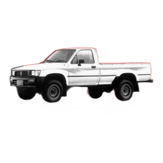
HILUX 1993
Toyota HILUX 1993 Manuals
Manuals and User Guides for Toyota HILUX 1993. We have
1
Toyota HILUX 1993 manual available for free PDF download: Repair Manual
Toyota HILUX 1993 Repair Manual (1400 pages)
Brand:
Toyota
| Category:
Automobile
| Size: 36 MB
Table of Contents
How to Use this Manual
3
Specifications
4
Vehicle Identification Number
5
Engine Serial Number
5
Identification Information
5
General Repair Instructions
6
Precaution for Vehicles Eqipped with a Catalytic Converter
9
Precaution for Vehicles with an Audio System with Anti-Theft System
9
Vehicle Lift and Support Locations
10
Abbreviations Used in this Manual
11
Glossary of SAE and Toyota Terms
13
Standard Bolt Torque Specifications
16
Maintenance Schedule
19
Maintenance Operations
21
Cold Engine Operations
21
Inspect Drive Belts
21
Replace Spark Plugs
21
Inspect Ignition Wiring and Distributor Cap
22
Inspect Air Filter
22
Replace Engine Oil and Oil Filter
22
Replace Engine Coolant
22
Inspect Charcoal Canister
23
Hot Engine Operations
24
Replace Gasket in Fuel Filler Cap
24
Replace Oxygen Sensor
24
Adjust Valve Clearance
24
Adjust Idle Speed
25
Adjust Fast Idle Speed (22R Engine)
26
Brakes Maintenance
29
Inspect Brake Line Pipes and Hoses
29
Inspect Front Brake Pads and Discs
30
Chassis Maintenance
31
Inspect Rear Brake Linings and Drums
31
Inspect Steering Linkage
31
Inspect Steering Gear Housing
32
Inspect Drive Shaft Boots
32
Inspect Ball Joints and Dust Covers
32
Check Oil Level in Manual/Automatic Transmission and Differential
33
Replace Manual Transmission Transfer (4 WD) and Differential Oil
35
Replace Automatic Transmission Fluid
37
Repack Front Wheel Bearings and Thrust Bush
38
Lubricate Propeller Shaft
38
Tighten Bolts and Nuts on Chassis and Body
39
Engine Mechanical
41
Troubleshooting (22R-E)
42
Engine Overheating
42
Hard Starting
42
Rough Idling
42
Engine Hesitates/Poor Acceleration
43
After Fire, Backfire
43
Excessive Oil Consumption
44
Poor Gasoline Mileage
44
Troubleshooting - 22R
45
Engine Dieseling
47
Engine Tune-Up
49
Idle HC/CO Concentration Check Method
50
Compression Check
51
Cylinder Head Components View
52
Preparation for Cylinder Head Removal
53
Remove Chamber with Throttle Body
54
Removal of Cylinder Head
55
Disassembly of Cylinder Head
57
Inspection and Cleaning of Cylinder Head Components
58
Clean Top of Pistons and Top of Block
58
Clean Combustion Chamber
58
Inspect Head for Flatness
59
Inspect Cylinder Head for Cracks and Clean Valves
59
Replace Valve Guide
60
Inspect and Grind Valves
61
Inspect and Clean Valve Seats
61
Inspect Valve Springs
62
Inspect Camshaft and Bearing Caps
63
Inspect Rocker Arms
64
Assembly of Cylinder Head
65
Inspect Intake and Exhaust Manifolds
65
Install Valves
65
Install Camshaft
66
Install Intake Manifold
66
Install EGR Valve with Vacuum Modulator
66
Install Exhaust Manifold
66
Installation of Cylinder Head
67
Apply Sealer to Cylinder Block
67
Install Rocker Arm Assembly
67
Install Cam Sprocket on Camshaft
67
Install Distributor Drive Gear and Fuel Pump Drive Cam
68
Adjust Valve Clearance (Cylinder Head)
68
Install Head Cover
69
Install Vane Pump with Bracket
70
Connect Fuel Hose to Delivery Pipe
70
Install Chamber with Throttle Body
70
Fill with Engine Oil (Cylinder Head)
71
Fill with Coolant
72
Perform Engine Adjustment
72
22R Cylinder Head - Preparation for Removal
73
22R Cylinder Head Removal
74
22R Cylinder Head Disassembly
75
22R Cylinder Head Assembly
76
Installation of Cylinder Head
77
Timing Chain Components View
80
Remove Oil Pan on Vehicle
80
Timing Chain Removal
81
Remove Drive Belts
81
Remove Chrankshaft Pulley
81
Remove Chain Cover Assembly
82
Remove Chain and Camshaft Sprocket
82
Remove Pump Drive Spline and Chankshaft Sprocket
82
Measure Chain and Sprocket Wear
83
Measure Chain Tensioner
83
Measure Chain Dampers
83
Installation of Timing Chain
84
Install Crankshaft Sprocket and Chain
84
Place Chain on Camshaft Sprocket
84
Install Timing Chain Cover Assembly
84
Install Chankshaft Pulley
85
Install Drive Belts
85
Install Oil Pan
86
Timing Chain - Post Installation
86
Cylinder Block - Preparation for Removal
87
Removal of Cylinder Block
89
Remove Vane Pump from Bracket
89
Remove Compressor from Bracket
89
Remove Exhaust Pipe
89
Remove Intermediate Shaft
90
Remove Engine Rear Mounting Bracket
90
Remove Engine with Transmission from Vehicle
90
Remove Transmission from Vehicle
90
Cylinder Block Components View
91
Cylinder Block - Preparation for Disassembly
91
Disassembly of Cylinder Block
92
Remove Oil Strainer and Rear Oil Seal Retainer
92
Measure Connecting Rod Thrust Clearance
92
Remove Connecting Rod Caps and Measure Oil Clearance
92
Push out Piston and Connecting Rod Assembly
93
Measure Crankshaft Thrust Clearance
93
Remove Main Bearing Caps and Measure Oil Clearance
94
Remove Crankshaft
94
Inspection of Cylinder Block
95
Measure Cylinder Bore
95
Remove Cylinder Ridge
95
Disassembly of Piston and Connecting Rod Assembly
96
Check Fit between Piston and Pin
96
Remove Piston Rings
96
Disconnect Connecting Rod from Piston
96
Inspection of Piston and Connecting Rod Assembly
97
Measure Piston Diameter
97
Measure Clearance between Piston Groove and Piston Ring
97
Measure Ring End Gap
97
Replacement of Rod Bushing
98
Inspect Piston Pin Fit
98
Inspect Connecting Rods
98
Remove Rod Bushing
98
Inspection and Repair of Crankshaft
99
Install New Rod Bushing
99
Hone New Bushing and Check Pin Fit in Connecting Rod
99
Grind Crank Pin And/Or Main Journal
99
Replacement of Rear Oil Seal
100
Boring of Cylinders
100
Select Oversized Piston
100
Bore and Hone Cylinders to Calculated Dimensions
100
Assembly of Piston and Connecting Rod Assembly
101
Install Bearing Inserts
101
Installation of Crankshaft, Piston and Connecting Rod Assembly
102
Install Upper Main Bearing in Cylinder Block
102
Install Main Bearing Caps
102
Install Piston and Connecting Rod Assembly
102
Install Rod Bearing Caps
103
Install Oil Strainer
103
Install Flywheel on Drive Plate on Crankshaft
103
Installation of Engine
104
Install Engine Mounting to Frame Bracket
104
Install Engine Rear Mounting Bracket
104
Install Exhaust Pipe
104
Install Compressor to Bracket (with A/C)
105
Install Vane Pump with Vane Pump Bracket (with Power Steering)
105
Engine - Post Installation
106
Install Radiator with Shroud
107
Fill the Engine with Engine Oil
107
Fill the Engine with Coolant
107
22R Cylinder Block - Preparation of Removal
108
Remove Radiator with Shroud
108
Postinstallation of Cylinder Block
110
Emission Control Systems
112
Emission Control System Component Layout and Schematic Drawing
114
Positive Crankcase Ventilation (PCV) System
115
Inspection of PCV Valve
116
Fuel Evaporative Emission Control (EVAP) System
117
Inspection of Fuel Vapor Lines, Fuel Tank and Filler Cap
117
Inspection of Charcoal Canister
118
Check for Clogged Filter and Stuck Check Valve
118
Clean Filter in Canister
118
Dash Pot (DP) System (M/T Vehicles)
119
Inspection of DP System
120
Check DP Setting Speed
120
Check Operation of VTV
120
Inspection of VTV
121
Exhaust Gas Recirculation (EGR) System
122
Inspection of EGR System
123
Check BVSV with Cold Engine
123
Check BVSV and EGR Vacuum Modulator with Hot Engine
123
Inspectoin of BVSV
124
Inspection of EGR Vacuum Modulator
124
Inspection of EGR Valve
124
Three-Way Catalyst (TWC) System
125
Inspection of Heat Insulator
126
Replacement of Catalytic Converter
126
Emission Control Systems (CARB.) Component Layout and Schematic
128
Inspection of Speed Sensor to VSV
135
Inspection of VSV
135
Inspection of Speed Sensor
136
Check On-Off Cycles of Speed Sensor
136
Mixture Control (MC) System (M/T Vehicles)
137
Inspection of MC System
138
Dash Pot (DP) System (A/T Vehicles)
139
Air Suction and Fuel System Feedback Control System
147
Inspection of Fuel Feedback Control System
150
Inspection of Reed Valve
151
Inspection of Vacuum Switch
151
Inspection of Thermal Switch
151
Inspection of Ox Sensor
153
Air Suction (AS) System
154
Inspection of as System
155
Inspection of Air Switching Valve
155
Inspection of VCV
155
Oxidation Catalyst (OC) System
157
Inspection of Exhaust Pipe Assembly
158
High Altitude Compensation (HAC) System
159
Inspection of HAC System
160
Checks at High Altitude
160
Check Ignition Timiing at Idle
160
Checks of HAC at Low Altitude
161
Check the Check Valve
161
Check Carburetor
161
Inspection of HAC Valve
163
Inspection of Check Valve
163
Inspectoin of Distribution Vacuum Advancer
163
Auxiliary Systems
164
Automatic Hot Air Intake (HAI) System
164
Inspection of HAI System
165
Check Air Control Valve Operation
165
Automatic Choke System Diagram
166
Inspection of Heater (Ceramic)
167
Inspection of Automatic Choke System
167
Choke Breaker (CB) System Diagram
168
Inspection of CB System
168
Check Choke Linkage and Diaphragm with Cold Engine
168
Choke Opener System Diagram
169
Inspection of Choke Opener System
170
Check BVSV Diaphragm and Linkage with Warm Engine
170
Inspection of BVSV
171
Check BVSV by Blowing Air into Pipe
171
Inspection of Diaphragm
171
Auxiliary Acceleration Pump (AAP) System Diagrams
172
Inspection of AAP System
173
Inspection of AAP Diaphragm
173
Deceleration Fuel Cut System Diagram
174
Deceleration Fuel Cut System Inspection
175
Inspection of Fuel Cut Solenoid Valve
176
Idle Advance System Diagrams
177
Idle Advance System Inspection
178
Inspection of Distributor Vacuum Advancer
178
Cold Mixture Heater (CMH) System Diagram
179
Inspection of CMH System
179
EFI System
181
EFI System - Precautions
184
When Car Is Equipped with a Mobile Radio System
185
Intake System
185
Electronic Parts (EFI)
185
EFI System Troubleshooting
189
Difficult to Start or no Start (Engine will Not Crank/Cranks Slowly)
190
Difficult to Start or no Start (Cranks OK)
191
Engine Often Stalls
193
Engine Sometimes Stalls
194
Rough Idling And/Or Missing
195
High Engine Idle Speed (no Drop)
197
Engine Backfires - Lean Air Fuel Mixture
198
Muffler Explosion (after Fire) - Rich Air Fuel Mixture - Misfire
199
Engine Hesitates And/Or Poor Acceleration
200
Diagnosis System
202
"Check Engine" Light Check
202
Output of Diagnostic Codes
202
Cancelling out Diagnostic Code
204
Diagnosis Indication
204
Diagnosis Codes
205
Inspection of Diagnosis Circuit
206
Troubleshooting with Volt/Ohmmeter
207
EFI System Check Procedure
207
Troubleshooting for EFI Electronic Circuit with Volt/Ohmmeter
208
Location of Fuse and Fusible Link
208
Voltage at ECU Wiring Connectors
209
Fuel Pump Diagrams
222
Fuel Pump On-Vehicle Inspection
223
Check Fuel Pressure
223
Removal of Fuel Pump
225
Installation of Fuel Pump
226
Cold Start Injector Diagrams
227
Removal of Cold Start Injector
227
Inspection of Cold Start Injector
227
Installation of Cold Start Injector
228
Pressure Regulator Diagrams
229
Removal of Pressure Regulator
229
Installation of Pressure Regulator
229
Injector Diagram
230
Injector On-Vehicle Inspection
230
Injector Removal
230
Inspection of Injector
231
Test Injection of Injectors
231
Injector Leakage Test
232
Installation of Injectors
233
Fuel Tank and Line Diagrams
235
Inspect Fuel Lines and Connections
235
Air Intake System
236
Air Flow Meter
236
Removal of Air Flow Meter
236
Measure Resistance of Air Flow Meter
236
Inspection of Air Flow Meter
237
Installation of Air Flow Meter
237
Air Valve Diagrams
238
Air Valve On-Vehicle Checks
238
Air Valve Removal
238
Throttle Body Diagrams
239
Inspection of Air Valve
239
Installation of Air Valve
239
Throttle Body On-Vehicle Check
239
Removal of Throttle Body
240
Check Throttle Body Position Sensor
240
Inspection of Throttle Body
241
Installation of Throttle Body
242
Electronic Control System Diagrams
243
Main Relay Diagram
244
Main Relay Inspection
244
Circuit Opening Relay Diagram
245
Inspection of Circuit Opening Relay
245
Solenoid Resistor Diagram
246
Inspection of Solenoid Resistor
246
Start Injector Time Switch Diagram
247
Inspection of Start Injector Time Switch
247
Water Thermo Sensor Diagram
248
Inspection of Water Thermo Sensor
248
Ox Sensor
249
Inspection of Feed Back Control
249
ECU Inspection
252
Measure Voltage of ECU
252
Measure Resistance of ECU
253
Fuel Cut RPM Inspection
254
Fuel System
255
Fuel System Precautions
256
Fuel System Troubleshooting
256
Fuel System On-Vehicle Inspection
257
Check Carburetor and Linkage
257
Check Float Level
257
Carburetor Components Diagram
258
Removal of Carburetor
259
Disassembly of Carburetor
260
Disassembly of Air Horn
260
Disassembly of Carburetor Body
262
Carburetor Cleaning
264
Inspection of Carburetor
264
Assembly of Carburetor
267
Assembly of Air Horn
269
Adjustment of Carburetor
271
Check and Adjust Throttle Valve Opening
271
Check Secondary Touch Angle
271
Check and Adjust Unloader
271
Check and Adjust Choke Opener
272
Check and Adjust Idle-Up
272
Check Choke Breaker
272
Check Air Valve and Metering Needle
272
Check Acceleration Pump
273
Inspect and Adjust Secondary Throttle Valve Lock System
273
Preset Idle Mixture Adjusting Screw
274
Check and Adjust Dash Pot
274
Installation of Carburetor
275
Adjustment of Carburetor (On-Vehicle)
276
Check Dash Pot Setting Speed
277
Install Air Cleaner
278
Idle Mixture Adjustment
279
Adjust Idle Speed and Idle Mixture
281
Plug Idle Mixture Adjusting Screw
281
Fuel Pump Components Diagram
282
Inspection of Fuel Pump
282
Fuel Tank and Line
284
Cooling System
285
Cooling System Troubleshooting
286
Water Pump Components Diagram
286
Removal of Water Pump
287
Inspection of Water Pump
287
Installation of Water Pump
288
Adjust Fan Belt Tension
288
Removal of Thermostat
289
Inspection of Thermostat
289
Installation of Thermostat
289
Cleaning of Radiator
290
Inspection of Radiator
290
Removal of Radiator
290
Lubrication System
291
Lubrication System Troubleshooting
292
Oil Pressure Check
292
Replacement of Engine Oil and Oil Filter
293
Oil Pump Components Diagrams
294
Removal and Disassembly of Oil Pump
294
Inspection of Oil Pump
295
Replace Front Oil Seal
296
Assembly and Installation of Oil Pump
296
Ignition System
297
Ignition System Precautions
298
Ignition System Troubleshooting
298
Electronic Spark Advance (ESA) for 22R-E
299
ESA System Circuit
299
Ignition System Inspection - On-Vehicle
300
Spark Test
300
Inspection of High Tension Cord
300
Inspection of Spark Plugs
300
Inspection of Ignition Coil (for 22R)
301
Inspection of Igniter (for 22R)
302
Inspection of Ignition Coil (for 22R-E)
303
Inspection of Igniter (for 22R-E)
304
On-Vehicle Inspection of Distributor
305
Removal of Distributor
306
Installation of Distributor
306
Starting System
307
Starting System Troubleshooting
308
Starter Components Diagram
309
Removal of Starter
310
Disassembly of Starter
310
Inspection of Starter
311
Commutator Inspection
311
Field Coil Inspection
312
Brushes Inspection
312
Brush Spring Inspection
313
Brush Holder Inspection
313
Clutch and Gears Inspection
313
Bearings Inspection (Starter)
313
Magnetic Switch Inspection
314
Assembly of Starter
314
Performance Test of Starter
316
Installation of Starter
317
Charging System
318
Charging System Precautions
319
Charging System Troubleshooting
319
Charging System On-Vehicle Inspection
320
Check Battery
320
Inspect Drive Belt
320
Check Discharge Warning Light Circuit
320
Check Charging Circuit Without Load
321
Removal of Alternator
322
Alternator Components Diagram
323
Disassembly of Alternator
323
Inspection and Repair of Alternator
326
Rotor Inspection
326
Stator Inspection
326
Brush and Brush Holder Inspection
327
Alternator Bearings Inspection
327
Assembly of Alternator
329
Installation of Alternator
331
Clutch Troubleshooting
333
Check and Adjustment of Clutch Pedal
334
Bleeding of Clutch System
335
Inspection of Clutch Start System
335
Inspection of Clutch Start Cancel Switch
336
Clutch Master Cylinder Components Diagram
338
Removal of Master Cylinder
338
Disassembly of Master Cylinder
338
Assembly of Master Cylinder
339
Clutch Release Cylinder Components Diagram
341
Inspection of Clutch Cylinder
342
Assembly of Release Cylinder
342
Installation of Release Cylinder
342
Clutch Unit Components Diagram
343
Removal of Clutch Unit
343
Inspection of Clutch Parts
344
Installation of Clutch Unit
345
G58, R150 and R150F Manual Transmission
348
G58, R150 and R150F Manual Transmission Precautions
350
G58, R150 and R150F Manual Transmission Troubleshooting
350
Removal and Installation of Transmission (2WD)
351
Removal and Installation of Transmission with Transfer (4WD)
360
Disassembly of Transmission (G58)
372
Input Shaft Assembly Components Diagram
384
Output Shaft Assembly Components Diagram
386
Disassembly of Output Shaft Assembly
386
Inspection of Output Shaft Assembly
389
Assembly of Output Shaft Assembly
391
Counter Gear Assembly and Reverse Idler Gear Components Diagram
395
Disassembly of Counter Gear Assembly
395
Inspection of Counter Gear Assembly
395
Assembly of Counter Gear Assembly
397
Inspection of Reverse Idler Gear
398
Transfer Adaptor Components Diagram
399
Front Bearing Retainer Components
401
Assembly of Transmission
402
Disassembly of Transmission (R150 and R 150F)
413
Input Shaft Assembly Components
423
Inspection of Input Shaft
423
Replacement of Bearing (Input Shaft Assembly)
423
Output Shaft Assembly Components
425
Inspect of Output Shaft Assembly
427
Counter Gear Assembly and Reverse Idler Gear Components
433
Inspection of Counter Gear
433
Extension Housing and Transfer Adaptor Components
436
Inspection and Replacement of Reverse Restrict Pin
437
Front Bearing Retainer Components Diagram
439
Replacement of Oil Seal
439
W55 and W56 Manual Transmission Description
454
W55 and W56 Manual Transmission Operation
455
W55 and W56 Manual Transmission - Special Service Tools
456
Recommended Tools
458
W55 and W56 Manual Transmission Troubleshooting
459
Manual Transmission Removal and Installation
460
Transmission with Transfer - Removal and Installation
461
Basic Subassembly Separation
464
Input Shaft Components Diagram
474
Input Shaft Inspection
474
Bearing Inspection (Input Shaft)
475
Output Shaft Components Diagram
477
Output Shaft Disassembly
477
Output Shaft Component Parts Inspection
480
Inspect Synchronizer Rings
480
Inspect Clearance of Shift Forks and Hub Sleeves
480
Inspect Output Shaft and Inner Race
481
Output Shaft Assembly
482
Counter Gear and Reverse Idler Gear Components
485
Counter Gear Component Parts Disassembly
485
Counter Gear and Reverse Idler Gear Component Parts Inspection
486
Counter Gear Component Parts Assembly
489
Front Bearing Retainer Component Diagram
491
Oil Seal Replacement
491
Reverse Restrict Pin Replacement
493
Basic Subassembly Reassembly
496
Manual Transmission - Service Specifications
510
Automatic Transmission
513
A43D Automatic Transmission Description
516
A43D Automatic Transmission General Specifications
517
Automatic Transmission Mechanical Operation
518
Hydraulic Control System
522
Automatic Transmission Basic Troubleshooting
523
Automatic Transmission Preliminary Check
526
Inspect Throttle Cable
527
Inspect Shift Lever Position
527
Inspect Park/Neutral Position Switch
527
Inspect Idle Speed (N Position)
527
Overdrive Control System Electric Control Circuit
528
Overdrive Control System Troubleshooting
529
Inspection of Overdrive Control Components
530
Automatic Transmission - Mechanical System Tests
532
Automatic Transmission - Hydraulic Test
534
Line Pressure Test
534
Governor Pressure Test
535
Automatic Transmission Road Test
536
Automatic Shift Schedule
539
Park Neutral Position Switch Inspection
539
Removal of Valve Body
540
Installation of Valve Body
541
Removal of Parking Lock Pawl
543
Installation of Parking Lock Pawl
543
Throttle Cable Removal
543
Throttle Cable Installation
544
Extension Housing - Replacement of Oil Seal
545
Removal of Extension Housing
545
Installation of Extension Housing
547
Governor Body Removal
548
Governor Body Installation
548
Transmission Removal and Installation
550
Check Torque Converter Clutch Installation
551
Torque Converter Clutch and Drive Plate Inspection
552
A340E Automatic Transmission
554
A340E Automatic Transmission Specifications
555
A340E Automatic Transmission Operation
556
Hydraulic Control System (A340E)
560
Electronic Control System (A340E)
561
A340E Automatic Transmission Troubleshooting
563
Diagnosis System Description
566
Check "O/D Off" Indicator Light
566
Read Diagnostic Trouble Code
567
Diagnostic Trouble Codes Table
568
Cancel out Diagnostic Trouble Code
568
Manual Shifting Test
573
Electronic Control Circuit Diagram
575
Electronic Control Components
576
Electronic Control Troubleshooting
577
Inspection of TT Terminal Voltage
582
Inspect Throttle Position Sensor Signal
582
Inspect Brake Signal
582
Inspect each Up-Shift Position
582
Inspection of Electronic Control Components
583
Inspect Solenoid
584
Check Solenoid Seals
584
Inspect Throttle Position Sensor
585
Inspect No. 2/No. 1 Vehicle Speed Sensor
585
Inspect Pattern Select Switch
585
Inspect O/D Switch
585
Stall Test
586
Time Lag Test
587
Hydraulic Test
588
Road Test
590
Automatic Transmission - On-Vehicle Repair
596
Removal of Throttle Cable
600
Installation of Throttle Cable
600
Removal of Sensor Rotor
604
Installation of Sensor Rotor
605
Removal and Installation of Transmission
606
Inspection of Torque Converter Clutch and Drive Plate
608
A340H Automatic Transmission
610
A340H Automatic Transmission Specifications
611
A340H Automatic Transmission Mechanical Operation
612
A340H Automatic Transmission Troubleshooting
618
Transfer High-Low Shift Range
654
Inspection of Park Neutral Position Switch
656
Removal of Valve Body And/Or Solenoid Valve
663
Installation of Valve Body And/Or Solenoid Valve
664
A340F Automatic Transmission
676
A340F Automatic Transmission Specifications
677
A340F Automatic Transmission Operation
678
Function of ECM
684
A340F Automatic Transmission Troubleshooting
685
A340F Automatic Transmission Diagnosis System
688
A340F Automatic Transmission - Manual Shifting Test
695
A340F Automatic Transmission - Electronic Control System
696
A340F Automatic Transmission - Troubleshooting Flow-Chart
698
A340F Automatic Transmission On-Vehicle Repair
716
Removal and Installation of Transmission (A340F )
722
Shift Lock System Components and Layout
725
Transfer Description
729
Transfer - Precautions
730
Transfer Troubleshooting
730
Removal of Transfer
731
Installation of Transfer
732
RF1A Type Transfer Components
734
Disassembly of Transfer (RF1A)
735
Input Gear Components
740
Replacement of Bearing (Input Gear)
740
Inspection of Hub Sleeve and Shift Fork Measure
741
Idler Gear Components
742
Counter Gear Components
744
Replacement of Bearings of Counter Gear
744
Output Shaft Components
746
Output Shaft Assembly Disassembly
746
Output Shaft Assembly Inspection
747
Assembly of Output Shaft
749
Front Drive Gear Components
750
Replacement of Front Drive Gear Bearings
750
Oil Seals Components
751
Replacement of Oil Seals
751
Assembly of Transfer
753
VF1A Type Transfer Components
759
Disassembly of Transfer (VF1A)
761
Oil Pump Body Components
770
Oil Pump Body Inspection
771
Driven Sprocket Components
774
Disassembly of Driven Sprocket
774
Assembly of Driven Sprocket
775
Rear Output Shaft Assembly Components
776
Disassembly of Rear Output Shaft Assembly
777
Inspection of Rear Output Shaft Assembly
779
Assembly of Rear Output Shaft Assembly
780
Input Shaft Components
783
Disassembly and Inspection of Input Shaft
783
Assembly of Input Shaft
784
Planetary Gear Components
785
Inspection of Planetary Gear
785
Oil Seals Components Diagram
788
Propeller Shaft Troubleshooting
801
Propeller Shaft Components
802
Propeller Shaft Removal
804
Propeller Shaft Disassembly
806
Propeller Shaft Inspection Components
807
Spider Bearing Replacement
808
Propeller Shaft Assembly
813
Propeller Shaft Installation
814
Propeller Shaft Service Specifications
818
Suspension and Axle Troubleshooting
821
Wheel Alignment
822
Front Axle Hub and Steering Knuckle Components
830
Front Axle Hub Disassembly
831
Inspection and Repair of Front Axle Hub
831
Assembly of Front Axle Hub
832
Steering Knuckle Removal
834
Inspection of Steering Knuckle
834
Installation of Steering Knuckle
835
Front Suspension Components
836
Ball Joint Inspection
837
Installation of Ball Joints
838
Torsion Bar Spring Removal
839
Installation of Torsion Bar Spring
839
Lower Suspension Arm and Shock Absorber
841
Replacement of Lower Arm Bushing
842
Installation of Lower Suspension Arm and Shock Absorber
842
Upper Suspension Arm Removal
844
Replacement of Upper Arm Bushing
844
Installation of Upper Suspension Arm
845
Strut Bar Removal
846
Installation of Strut Bar
846
Stabilizer Bar Removal
847
Stabilizer Bar Installation
847
Free Wheeling Hub Components
848
Removal of Free Wheeling Hub
849
Disassembly of Free Wheeling Hub
849
Inspection of Free Wheeling Hub
850
Assembly of Free Wheeling Hub
850
Installation of Free Wheeling Hub
852
Inspection and Replacement of Steering Knuckle
856
Front Drive Shaft Components
861
Removal of Front Drive Shaft
861
Disassembly of Front Drive Shaft
862
Assembly of Front Drive Shaft
863
Installation of Front Drive Shaft
866
Front Differential
868
On–Vehicle Replacement of Rear Oil Seal
868
Removal of Front Differential
872
Replacement of Side Oil Seal (Without A.D.D.)
874
Replacement of Side Oil Seal (with A.D.D.)
876
Replacement of LH Side Oil Seal
876
Replacement of RH Side of Oil Seal
879
Disassembly and Assembly of Differential (with out A.D.D.)
881
Inspection and Replacement of Differential
885
Assembly of Differential
889
Disassembly and Assembly of Differential (with A.D.D.)
897
Inspection and Replacement of Actuator
908
Installation of Front Differential
921
A.D.D. Control System Components
922
A.D.D. Control System Electrical Circuit
923
A.D.D. Control System - Inspection of Components
924
Inspection of Ball Joints
927
Removal of Ball Joints
927
Torsion Bar Spring Removal and Installation
929
Removal of Lower Suspension Arm and Shock Absorber
931
Placement of Lower Suspension Arm Bushing
932
Removal Upper Suspension Arm
934
Removal of Stabilizer Bar
937
Installation of Stabilizer Bar
937
Rear Axle Shaft (Single Tire) Components
938
Removal of Rear Axle Shaft
939
Inspection and Repair of Rear Axle Shaft Components
939
Installation of Rear Axle Shaft
941
Rear Axle Shaft and Axle Hub (Double Tire) Diagram
942
Inspection of Rear Axle Shaft Components
943
Disassembly of Rear Axle Hub
944
Inspection and Repair of Rear Axle Hub
944
Assembly of Rear Axle Hub
946
Differential Components
949
On-Vehicle Replacement of Oil Seal
950
Removal of Differential
951
Disassembly of Differential
952
Replacement of Differential Case Component Parts
956
Assembly of Differential (Suspension and Axle)
959
Installation of Differential (Suspension and Axle)
966
Rear Suspension
968
Shock Absorber Components
968
Removal of Shock Absorber
968
Inspection of Shock Absorber
969
Disposal of Shock Absorber
969
Installation of Shock Absorber
969
Leaf Spring Components
970
Removal of Leaf Spring
972
Replacement of Bushing (Leaf Spring)
973
Replacement of Leaf Spring
973
Installation of Leaf Spring
974
Removal and Installation of Stabilizer Bar
977
Brake System
979
Brake System Precautions
980
Brake System Troubleshooting
980
Low or Spongy Pedal
980
Brakes Drag/Brakes Pull
980
Hard Pedal but Brakes Inefficient
981
Snapping or Clicking Noise When Brakes Are Applied
981
Scraping or Grinding Noise When Brakes Are Applied
981
Squeaking, Squealing, Groaning, Chattering Noise When Brakes Applied
982
Squealing and Squeaking Noise When Brakes Are Not Applied
982
Groaning, Clicking or Rattling Noise When Brakes Are Not Applied
983
Check and Adjustment of Brake Pedal
984
Operational Test of Brake Booster
985
Bleeding of Brake System
986
Check and Adjustment of Parking Brake
987
Removal of Master Cylinder (Brake System)
988
Master Cylinder Components Diagram (Brake)
989
Disassembly of Master Cylinder (Brake)
989
Inspection of Master Cylinder (Brake)
990
Assembly of Master Cylinder (Brake)
991
Installation of Master Cylinder (Brake)
993
Removal of Brake Booster
994
Installation of Brake Booster
995
Front Brake 4WD (S12 + 12 Type Disc) Components
996
Replacement of Brake Pads
996
Removal of Cylinder
998
Disassembly of Cylinder
999
Inspection and Repair of Front Brake Components
1000
Assembly of Cylinder
1001
Installation of Cylinder
1002
Rear Brake 4WD Components
1003
Removal of Rear Drum Brake
1003
Inspection and Repair of Rear Brake Components
1006
Assembly of Rear Brakes
1007
Load Sensing Proportioning and By-Pass Valve (LSP & BV) Components
1012
Check and Adjustment of Fluid Pressure
1012
Removal of LSP & BV or LSPV
1015
Disassembly of LSP & BV or LSPV Assembly
1015
Inspection of LSP & BV or LSPV
1016
Assembly of LSP & BV or LSPV
1016
Installation of LSPV and BV or LSPV
1017
Rear-Wheel Anti-Lock Brake System Description
1018
Rear-Wheel Anti-Lock Brake System Wiring Diagram
1019
Rear-Wheel Anti-Lock Brake System Connectors
1020
Rear-Wheel Anti-Lock Brake System Diagnosis System
1021
Inspection of Diagnosis System
1021
Clearing of Diagnostic Trouble Codes
1024
Rear–Wheel Anti–Lock Brake System Troubleshooting
1026
"Rear Antilock" Warning Light Comes on
1026
"Rear Antilock" Warning Light Comes on and off
1029
Rear–Wheel Anti–Lock Brake System Works Inefficiently
1031
Deceleration Sensor and Speed Sensor Diagnosis System Inspection
1032
Brake Actuator Components
1035
Inspection of Brake Actuator
1035
Check Brake Fluid Pressure
1035
Check Power Steering Fluid Pressure
1036
Check Relation between Brake Fluid and Power Steering Fluid Pressure
1036
Check Actuator Operation
1037
Removal of Brake Actuator
1038
Installation of Brake Actuator
1040
Bleeding of Rear-Wheel Anti-Lock Brake System
1042
Control Relay
1043
Inspection of Solenoid Relay
1043
Speed Sensor Inspection
1044
Inspection of Speed Sensor and Sensor Rotor Serrations
1046
Inspection of Deceleration Sensor
1047
Rear–Wheel Anti–Lock Brake System Circuit Inspection
1048
Steering Troubleshooting
1051
Steering On-Vehicle Inspection
1052
Steering Wheel Freeplay
1052
Steering Oil Level Check
1052
Steering Column Removal and Installation
1053
Non–Tilt Steering Column Components
1054
Disassembly of Steering Column
1055
Inspection and Replacement of Non-Tilt Steering Column
1056
Assembly of Non-Tilt Steering Column
1057
Tilt Steering Column Components
1058
Inspection and Replacement of Steering Column
1062
Assembly of Tilt Steering Column
1063
Removal and Installation of Manual Gear Housing
1068
Disassembly of Manual Gear Housing
1070
Inspection and Replacement of Manual Gear Housing
1070
Assembly of Steering Gear Housing
1072
Manual Gear Housing (4WD)
1075
Disassembly of Manual Gear Housing (4WD)
1077
Inspection and Replacement of Manual Gear Housing (4WD)
1079
Power Steering Description
1085
Power Steering On-Vehicle Inspection
1086
Vane Pump
1086
Power Steering Fluid Level Check
1087
Replacement of Power Steering Fluid
1088
Bleeding of Power Steering Fluid System
1089
Power Steering Pump Removal and Installation
1092
Power Steering Pump Components
1094
Disassembly of Power Steering Pump
1094
Inspection of Power Steering Pump
1097
Assembly of Power Steering Pump
1099
Power Steering Pump - RN Series
1103
Removal and Installation of Gear Housing (2WD)
1112
Gear Housing (2WD) Components
1114
Disassembly of Gear Housing
1115
Inspection and Replacement of Gear Housing
1117
Assembly of Gear Housing
1120
Gear Housing - (4WD)
1122
Progressive Power Steering (PPS) Electronic Circuit
1134
Progressive Power Steering (PPS) Troubleshooting
1135
Electronic Control System
1138
Solenoid Valve Diagram
1138
Check Solenoid Operation
1138
Power Steering ECU Inspection
1139
Steering Linkage (2WD) Removal and Installation
1140
Disassembly of Idler Arm Bracket
1142
Assembly of Idler Arm Bracket
1143
Steering Linkage (4WD) Removal and Installation
1144
Body Electrical System
1149
Body Electrical System
1150
Distinction of Male and Female Connectors
1150
Replacement of High Current Fuse, Medium Current Fuse and Fuse
1151
Check for Voltage
1152
Check for Continuity and Resistance
1152
Check the Bulb
1153
Check for Short Circuit
1153
Power Source Parts Location
1154
Power Source Wiring Diagram
1155
Ignition Switch Parts Location, Wiring and Connector Diagrams
1156
Ignition System Inspection
1156
Key Confine Prevention System
1157
Lighting System Parts Location
1158
Lighting System Wiring and Connector Diagrams
1159
Lighting System Troubleshooting
1162
Adjustment of Light Aiming
1164
Lighting System Parts Replacement
1164
Disassembly of Combination Switch
1165
Assembly of Combination Switch
1166
Headlight, Taillight and Daytime Running Light System Checks
1167
Inspect Daytime Running Light Relay
1168
Lights – on Warning System Inspection
1170
Illuminated Entry System Inspection
1170
Turn Signal and Hazard Warning System Inspection
1171
Wiper and Washer System Parts Location
1172
Wiper and Washer System Troubleshooting
1173
Wiper System Inspection
1174
Washer System Inspection
1176
Combination Meter Parts Location
1177
Meter Circuit (W/O Tachometer)
1178
Meter Circuit (W/ Tachometer)
1179
Combination Meter Troubleshooting
1180
Speedometer System Inspection
1181
Fuel Gauge System Inspection
1182
Fuel Level Warning System Inspection
1183
Engine Coolant Temperature Gauge System Inspection
1184
Low Oil Pressure Warning System Inspection
1185
Brake Warning System Inspection
1186
Seat Belt Warning System Inspection
1188
Open Door Warning System Inspection
1189
Illumination Control System Inspection
1190
Inspect Light Control Rheostat
1190
Power Window Control System Parts Location, Wiring Diagram
1191
Power Window Control System Troubleshooting
1192
Power Window Control System Parts Inspection
1192
Power Door Lock Control System Parts Location and Wiring Diagram
1196
Power Door Lock Control System Troubleshooting
1197
Power Door Lock Control System Parts Inspection
1197
Inspect Door Lock Motor
1198
Inspect Door Lock Control Relay
1199
Power Mirror Control System Parts Location and Wiring Diagram
1201
Power Mirror Control System Troubleshooting
1202
Inspect Mirror Switch
1202
Inspect Mirror Motor
1203
Cruise Control System Parts Location
1204
Cruise Control System Wiring Diagram
1206
Cruise Control System Connector Diagrams
1207
Cruise Control System Description
1208
Cruise Control System Diagnosis System
1209
Cruise Control System Troubleshooting
1211
Inspection of Cruise Control Switch Circuit
1216
Inspection of Actuator Circuit
1217
Inspection of Speed Sensor Circuit
1219
Inspection of Stop Light Switch Circuit
1220
Inspection of Parking Brake Switch Circuit
1221
Inspection of Clutch Switch Circuit
1222
Inspection of Park/Neutral Position Switch Circuit
1223
Inspection of Vacuum Circuit
1224
Inspection of ECM Solenoid Circuit
1226
Inspection of ECU Circuit
1227
Inspect Vacuum Pump
1230
Inspect Actuator
1230
Audio System Parts Location
1231
Audio System Wiring and Connector Diagrams
1232
Audio System Description
1236
Radio Wave Bands
1236
Maintenance of Tape Player
1237
Anti–Theft System
1237
How to Use Diagnostic Chart
1238
Audio System Troubleshooting
1239
Troubleshooting for Anti-Theft System
1240
Radio - no Power Coming in
1241
Power Coming In, but Radio Not Operating
1242
Noise Present, but AM-FM Not Operating
1242
Either Speaker Does Not Work
1243
Either am or FM Does Not Work Reception Poor, few Preset Tuning Bands
1244
Sound Quality Poor (Radio)
1245
Cannot Set Station Select Button, Preset Memory Disappears
1246
Cassette Tape Cannot be Inserted
1247
Cassette Tape Inserts, but no Power
1248
Power Coming In, but Tape Player Not Operating
1249
Sound Quality Poor (Volume Faint)
1251
Tape Jammed, Malfunction with Tape Speed or Auto-Reverse
1251
APS, Skip, RPT Buttons Not Operating
1252
Cassette Tape will Not Eject
1252
Antenna-Related Troubles
1253
Noise Produced by Vibration or Shock While Driving (Audio System)
1254
Noise Produced When Engine Starts (Audio System)
1255
Inspect Antenna Motor
1256
Removal and Installation of Antenna Rod
1257
Clock Troubleshooting
1258
Body - General Information
1260
Adjustment of Hood
1261
Front Door Components
1262
Adjustment of Front Door
1264
Disassembly of Front Door
1264
Remove Rear View Mirror
1265
Remove Door Trim
1265
Remove Ventilator Window
1265
Remove Inner and Outer Weatherstrip
1266
Remove Outside Handle and Door Lock
1266
Replacement of Glass
1267
Assembly of Front Door
1267
Windshield Moulding Components
1271
Removal of Windshield Moulding
1271
Replacement of Fastener
1272
Installation of Windshield Moulding
1273
Wheel Arch Moulding Components
1274
Replacement of Front/Rear Wheel Arch Moulding
1274
Windshield - Adhesive Type
1275
Removal of Windshield
1276
Windshield Installation
1277
Back Window Components
1280
Removal of Back Window
1280
Disassembly of Back Window Assembly
1281
Assembly of Back Window Assembly
1281
Installation of Back Window
1282
Quarter Window (Xtra Cab) Components
1283
Removal of Quarter Window
1283
Installation of Quarter Window
1284
Moon Roof Components
1285
Removal of Moon Roof
1286
Installation of Moon Roof
1287
Disassembly of Removable Roof
1289
Assembly of Removable Roof
1289
Instrument Panel Components
1290
Removal of Instrument Panel
1292
One–Touch Tail Gate Components
1297
Removal of Tail Gate Lock
1297
Installation of Tail Gate Lock
1298
Removal and Installation of Tail Gate Lock Control
1298
Front Seat Components
1299
Rear Jump Seat Components
1300
Front Seat Belt Components
1301
Rear Jump Seat Belt Components
1302
Seat Belts Testing
1303
Manual Type
1303
Body Dimensions
1304
Frame Dimensions
1307
Air Conditioning System
1321
Air Conditioning System
1322
Refrigeration System Information
1322
Handling Precautions for Gas–Cylinder Type Gas Leak Tester
1324
Precautions When Replacing Parts in Refrigerant Line
1324
Precautions When Charging Refrigerant
1325
Air Conditioning System Circuit
1326
Air Conditioning System Components
1327
Refrigeration Cycle
1328
Principle of A/C Electrical Circuit
1329
How Is Magnetic Clutch Energized?
1329
Air Conditioning Troubleshooting
1330
Inspection of Refrigeration System with Manifold Gauge Set
1332
Air Conditioning System On-Vehicle Inspection
1335
Checking of Refrigerant Volume
1336
Installation of Manifold Gauge Set
1336
Compressor On-Vehicle Inspection
1337
Removal of Compressor
1338
Disassembly of Magnetic Clutch
1339
Assembly of Magnetic Clutch
1341
Installation of Compressor
1342
Receiver On-Vehicle Inspection
1343
Removal of Receiver
1343
Installation of Receiver
1343
Condenser On-Vehicle Inspection
1344
Removal of Condenser
1344
Installation of Condenser
1344
On-Vehicle Inspection of Expansion Valve
1345
Removal of Cooling Unit
1345
Disassembly of Cooling Unit
1346
Evaporator Inspection
1347
Assembly of Cooling Unit
1347
Installation of Cooling Unit
1347
Refrigerant Lines On-Vehicle Inspection
1348
Replacement of Refrigerant Lines
1348
AC Switch On-Vehicle Inspection
1349
Inspection of Dual Pressure Switch
1349
Thermistor Inspection
1350
Removal of Thermistor
1350
Installation of Thermistor
1350
Inspection of A/C Cut off Relay
1350
Air Conditioning Amplifier Inspection
1351
Vacuum Hose Circuit
1352
Vacuum Switches Valve (VSV) Inspection
1352
Heater Parts Location
1354
Heater Wiring and Connector Diagrams
1354
Heater Troubleshooting
1355
Damper Positions Diagram
1355
Heater Inspection and Adjustment
1356
Heater Parts Inspection
1357
Service Specifications - Maintenance
1359
EFI System Data
1362
Service Specifications
1367
Clutch Specifications
1367
Automatic Transmission Specifications
1375
Transfer Specifications
1381
Propeller Shaft Specifications
1385
Suspension and Axle Specifications
1386
Brake System Specifications
1393
Steering Specifications
1395
Body Specifications
1398
Lubricant Specifications
1399
Advertisement
Advertisement
Related Products
Toyota Hilux 2012
Toyota HILUX 2007
Toyota HILUX 2008
Toyota HILUX SC
Toyota HILUX DC
Toyota HILUX DOUBLECAB 2017
Toyota Hi-Lux 1973
TOYOTA HIGLANDER - CONDENSED BROCHURE 2011
Toyota Hiace
Toyota HIGHLANDER HYBRID 2008
Toyota Categories
Automobile
Automobile Accessories
Car Navigation system
Sewing Machine
Engine
More Toyota Manuals
Login
Sign In
OR
Sign in with Facebook
Sign in with Google
Upload manual
Upload from disk
Upload from URL