Sign In
Upload
Manuals
Brands
Toshiba Manuals
Heat Pump
HWS-1501CSHM3-E(-UK)
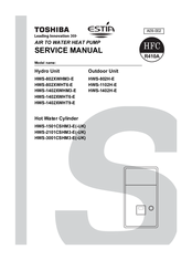
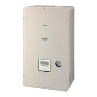
Toshiba HWS-1501CSHM3-E(-UK) Manuals
Manuals and User Guides for Toshiba HWS-1501CSHM3-E(-UK). We have
2
Toshiba HWS-1501CSHM3-E(-UK) manuals available for free PDF download: Service Manual
Toshiba HWS-1501CSHM3-E(-UK) Service Manual (169 pages)
AIR TO WATER HEAT PUMP
Brand:
Toshiba
| Category:
Heat Pump
| Size: 9.99 MB
Table of Contents
Service Manual
1
Table of Contents
2
1 Safety Precautions
4
Safety During Installation and Service
7
2 New Refrigerant (R410A)
7
Installing Refrigerant Pipe
8
Steel Pipe and Joint
8
The Minimum Wall Thickness of Socket Joints
8
Wall Thickness of Copper Pipe
8
Flare and Precautions
9
Flare Processing Related Dimension for the Unit
9
Processing of Piping Materials
9
Relationship between Flare Nut and Flare Surface
9
Flare Connecting Procedure and Precautions
10
2-3.Tools
11
2-3-1.Necessary Tools
11
Recharging of Refrigerant
12
Configuration of Refrigerant Charging
12
Brazing of Pipes
14
Flux
14
Materials of Brazing
14
Brazing Method to Prevent Oxidation
14
2-5-3.Brazing
14
3 Specifications
16
4 Outside Drawing
18
4-1.Hydro Unit
18
4-2.Outdoor Unit
19
Hot Water Cylinder Drawing
21
4-3.Hot Water Cylinder
21
5 Wiring Diagram
22
5-1.Hydro Unit
22
5-2.Outdoor Unit
23
5-3.Hot Water Cylinder Unit
24
6 Key Electric Component Rating
25
6-1.Hydro Unit
25
6-2.Outdoor Unit
27
6-3.Hot Water Cylinder Unit
29
Water Heat Exchange Control Board
30
Outdoor Control Board
31
7 Refrigeration Cycle / Water System Diagram
33
7-1.Water System Diagram
33
Installation Example of Water Circuit
34
Refrigeration Cycle System Diagram
35
8 Operational Description
36
Operation Control
37
Hot Water Supply Operation
38
Heating Operation
38
Cooling Operation
39
Simultaneous Operations of "Hot Water Supply" and "Cooling"
43
Boiler-Assisted Heating Operation
43
Hot Water Boost Operation
44
Anti Bacteria Operation
45
Night Set Back Operation
46
Frost Protection Operation
46
Auto Operation
47
Nighttime Low-Noise Operation
48
Hydro Unit Control
49
Capacity Control
49
High Temperature Release Control
50
Low Temperature Release Control
50
Heater Control
51
Control at the Time of Heating Heater Operation
52
Heater Control at the Time of Defrosting
52
Forcible Heater Energization
52
Circulation Pump Control
53
Flow Switch Operation
53
Mixing Valve Control (2-Temperature Heating Control)
54
Automatic Restart Control
55
Piping Freeze Prevention Control
55
High Return Water Protect Control
56
Room Temperature Thermostat Control
57
Heating Thermostat Operation
57
Cooling Thermostat Operation
57
Output Signal Control
57
Outdoor Unit Control
58
PMV (Pulse Motor Valve) Control
58
Discharge Temperature Release Control
58
Current Release Control
59
Current Releases Shift Control
59
Outdoor Fan Control
60
Hot Water Supply and Heating Fan Control
61
Defrosting Control
62
Winding Heating Control
63
Short Circuit Operation Prevention Control
63
Over Current Protection Control
63
9 Method of Defect Diagnosis
65
9-1.Matters to be Confirmed First
65
9-1-2.Check for any Miswiring of the Connection Cables between the Hydro Unit and the Outdoor Unit
66
About the Installation of the Temperature Sensor
66
Check the Power Supply Voltage
66
Non-Defective Operation (Program Operation)
66
How to Cancel a Check Code on the Remote Controller
67
How to Determine from the Check Code on the Remote Control
67
Outline of the Determination Diagram
67
Procedure of Defect Diagnosis
67
How to Diagnose by Error Code
68
Defect Mode Detected by the Outdoor Unit
71
Defect Mode Detected by the Remote Control
74
Diagnosis Flow Chart for each Error Code
75
Hydro Unit Failure Detection
75
Error Temperature Rise and Error Short Circuit
76
Error Freeze Prevention Control
78
Error Piping Freeze Prevention Control
79
Error Pressure Switch Operation (Hot Water Supply/Heating Operation)
80
Error lo Pressure Sensor Lowering Operation Failure
81
Error Overheat Prevention Thermostat Failure
82
Error Release Protection Operation
83
Error Heating or Hot Water Supply Heater Failure
84
Error
85
Error TC Sensor Failure
86
Error TD Sensor Failure
86
Error te Sensor Failure
86
Error TL Sensor Failure
87
Error to Sensor Failure
87
Error TWI Sensor Failure
87
Error TFI Sensor Failure
88
Error TTW Sensor Failure
88
Error TWO Sensor Failure
88
Error THO Sensor Detach Failure
89
Error THO Sensor Failure
89
Error lo Pressure Sensor Detach Failure
90
Error TFI Detach Failure
90
Error EEPROM Failure
91
Error Enhanced IC Failure
91
Diagnosis Procedure for each Check Code
92
Outdoor Unit Failure Detection
92
Abnormal Outlet Temperature
95
Power Source Failure (Voltage Defective, Open Phase)
95
Gas Leakage Detection
96
Heat Sink Overheat Failure
96
4-Way Valve Invert Failure
97
Hi Pressure Protection Operation
98
Blower System Failure
99
Compressor Drive Element Shorted out
99
Discharge Abnormality
100
Discharge Temperature Sensor (TD) Failure
100
Heat Exchanger Temperature Sensor (TE) Failure
100
Outside Air Temperature Sensor (TO) Failure
100
Heat Exchanger Sensor (TE, TS) Wrong Wiring
101
Suction Temperature Sensor (TS) Failure
101
Temperature Sensor, Temperature-Resistance Characteristic Table
102
9-5-1.Operation Check Mode
103
Operation Check by PC Board Switch
103
9-6-1.Hydro Unit
104
Brief Method for Checking the Key Components
104
9-6-2.Outdoor Unit
105
10 Hydro Unit and Outdoor Unit Settings
106
Hydro Unit Function Code Setting
107
How to Set Remote Controller Function Code
107
Function Code Table
108
Remote Controller Function Code Table
109
Trial Operation
110
Auto Curve Setting
111
Time Setting
112
Scheduled Operation Setting
113
How to Start and Cancel Schedule Operation
114
Frost Protection Setting
114
NIGHT Operation Setting
115
How to Set NIGHT Operation Start and End Time
115
Anti Bacteria Setting
116
Hot Water Boost Setting
117
Nighttime Low-Noise Setting
117
Forced Defrosting Setting
118
Rated Operation Setting
118
Display Function of Set Temperature and Other Settings
119
Failure History Calling Function
120
Outdoor Unit Setting
121
Service Support Functions (LED Indication, Switch Operation Method)
122
Abnormality Indication
124
Sensor, Current, Compressor Operation Frequency
125
Special Operation for Maintenance and Inspection
126
11 How to Exchange Main Parts
128
Hydro Unit Parts Exchange
128
Remote Controller Exchange
129
Water Heat Exchanger Board Exchange
129
Relay Board Exchange
130
Electric Parts Assembly Exchange
130
Side Board Exchange
131
Upper Board Exchange
131
Bottom Board Exchange
131
Expansion Vessel Exchange
132
Relief Valve Exchange
132
Air Vent Valve Exchange
132
Pump Exchange
133
Flow Switch Exchange
134
Manometer Exchange
134
Heater Assembly Exchange
135
TC Sensor, TWI Sensor, TWO Sensor, THO Sensor Exchange
135
Water Heat Exchanger Assembly Exchange
136
Outdoor Unit Parts Exchange
137
Outlet Cabinet Exchange
138
Side Cabinet Exchange
138
Electric Parts Replacement (Outdoor Unit)
139
Fan Motor Exchange
141
Compressor Exchange
142
Pulse Motor Valve Coil Exchange
145
Fan Guard Exchange
146
12 Periodic Inspection Items
155
13 Part Exploded View, Part List
156
Advertisement
Toshiba HWS-1501CSHM3-E(-UK) Service Manual (212 pages)
Brand:
Toshiba
| Category:
Heat Pump
| Size: 9.56 MB
Table of Contents
Service Manual
1
Table of Contents
2
1 Safety Precautions
4
2 New Refrigerant (R410A)
7
2-1.Safety During Installation and Service
7
2-2.Installing Refrigerant Pipe
8
2-2-1.Steel Pipe and Joint
8
2-2-2.Processing of Piping Materials
9
2-3.Tools
11
2-3-1.Necessary Tools
11
2-4.Recharging of Refrigerant
12
2-5.Brazing of Pipes
14
2-5-1.Materials of Brazing
14
2-5-2.Flux
14
2-5-3.Brazing
14
3 Specifications
16
4 Outside Drawing
19
4-1.Hydro Unit
19
4-2.Outdoor Unit
20
4-3.Hot Water Cylinder
22
5 Wiring Diagram
23
5-1.Hydro Unit
23
5-2.Outdoor Unit (Single Phase Type)
24
5-3.Outdoor Unit (3 Phase Type)
25
5-4.Hot Water Cylinder Unit
26
6 Key Electric Component Rating
27
6-1.Hydro Unit
27
6-2.Outdoor Unit
29
6-3.Hot Water Cylinder Unit
32
6-4.Water Heat Exchange Control Board
33
6-5.Outdoor Control Board (Single Phase Type)
34
6-6.Outdoor Unit Control (3 Phase Type)
36
MCC-1596 (Compressor IPDU)
36
MCC-1597 (Fan Motor IPDU)
37
MCC-1599 (Interface (CDB))
38
MCC-1600 (Noise Filter)
39
7 Refrigeration Cycle / Water System Diagram
40
7-1.Water System Diagram
40
7-2.Refrigeration Cycle System Diagram
42
8 Operational Description
44
Outdoor Fan
79
Way Valve
79
9 Method of Defect Diagnosis
82
9-1.Matters to be Confirmed First
82
9-1-1.Check the Power Supply Voltage
83
9-1-2.Check for any Miswiring of the Connection Cables between the Hydro Unit and the Outdoor Unit
83
9-1-3.About the Installation of the Temperature Sensor
83
9-2.Non-Defective Operation (Program Operation)
83
9-3.Outline of the Determination Diagram
84
9-3-1.Procedure of Defect Diagnosis
84
9-3-2.How to Determine from the Check Code on the Remote Control
84
9-3-3.How to Cancel a Check Code on the Remote Controller
84
9-3-4.How to Diagnose by Error Code
85
9-4.Diagnosis Flow Chart for each Error Code
92
9-4-1.Hydro Unit Failure Detection
92
9-4-2.Outdoor Unit Failure Detection
110
9-4-3.Temperature Sensor, Temperature-Resistance Characteristic Table
123
9-5.Operation Check by PC Board Switch
124
9-5-1.Operation Check Mode
124
9-6.Brief Method for Checking the Key Components
125
9-6-1.Hydro Unit
125
9-6-2.Outdoor Unit
126
10 Hydro Unit and Outdoor Unit Settings
128
11 Replacement of the Service P.C. Board
153
12 How to Exchange Main Parts
154
13 Periodic Inspection Items
194
14 Part Exploded View, Part List
195
Advertisement
Related Products
Toshiba ESTIA HWS-1501CSHM3-E
Toshiba ESTIA HWS-1501CSHM3-UK
Toshiba HWS-1403XWHM3-E
Toshiba HWS-1403XWHT6-E
Toshiba HWS-1103H-E
Toshiba HWS-1404H8-E
Toshiba HWS-1604H8-E
Toshiba HWS-11-4H8R-E
Toshiba HWS-1404H8 series
Toshiba HWS-1104H8R series
Toshiba Categories
Laptop
Air Conditioner
TV
LCD TV
All in One Printer
More Toshiba Manuals
Login
Sign In
OR
Sign in with Facebook
Sign in with Google
Upload manual
Upload from disk
Upload from URL