Sign In
Upload
Manuals
Brands
Teledyne RD Instruments Manuals
Marine Equipment
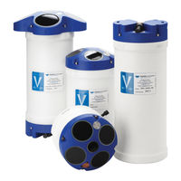
SENTINEL V REAL-TIME
Teledyne RD Instruments SENTINEL V REAL-TIME Manuals
Manuals and User Guides for Teledyne RD Instruments SENTINEL V REAL-TIME. We have
1
Teledyne RD Instruments SENTINEL V REAL-TIME manual available for free PDF download: Operation Manual
Teledyne RD Instruments SENTINEL V REAL-TIME Operation Manual (343 pages)
Brand:
Teledyne RD Instruments
| Category:
Marine Equipment
| Size: 21 MB
Table of Contents
Table of Contents
3
Chapter 1 - Self -Contained
17
Overview
17
Sentinel V Features
18
Figure 1. Sentinel V100 5 Beam Overview with Battery Pack and Optional End-Cap Connector
18
Figure 2. Sentinel V20 with D Cell Batteries and Optional End-Cap Call out Beam Numbers
19
Figure 3. External Battery Case Overview
20
Available Options
21
System Inventory
22
Software Overview
22
Computer Considerations
23
Table 1. Supported Operating Systems and Browsers
23
Power Considerations
24
Touch Sensor Response / System Beeps
25
Connecting to the Sentinel V ADCP
25
Using the Wireless Connection
26
Connect
27
Touch Sensor
27
Start Readyv
28
Figure 4. Using the Readyv Wireless Connection
29
Connecting to Another ADCP
30
Restoring a Readyv Lost Connection
31
Wireless Connection Common Issues
32
Time Sentinel V Overview
37
Sentinel V Real-Time Features
38
Figure 5. Real-Time (RT) Housing Overview
38
Available Real-Time Options
39
Health & Environment Monitoring Sensors
40
Comparing Self-Contained & Real-Time
41
Real-Time System Inventory
42
Real-Time Software Overview
43
Real-Time Computer Considerations
44
Table 2. Supported Operating Systems and Browsers for Sentinel V Real-Time Utilities Page
44
Real-Time Power Considerations
45
Real-Time Touch Sensor Response / System Beeps
46
Real-Time ADCP Commands
46
Connecting to the Sentinel V Real-Time
47
Figure 6. Sentinel V Real-Time Serial Connection
47
Figure 7. Sentinel V Real-Time Ethernet Connection
47
Using Sentinel V RT Utilities
48
Using Ethernet Communications
49
Using Directed UDP Output
49
Using UDP Broadcast Output
50
Using the Sentinel-V Real-Time Utilities Page
50
Installing Sentinel-V Real-Time Firmware Upgrades
50
Downloading Sentinel V Real-Time Log Files
52
Figure 8. Sentinel V RT Utilities Page
52
Installing Feature Upgrades
53
Using the Trigger
54
Chapter 1 C - Switching Rt and Sc Modes
55
Switching RT and SC Modes
55
Switching to the Sentinel V Real-Time Mode
56
Switching to the Sentinel V Self-Contained Mode
57
Chapter 2 - Using Readyv
59
Figure
59
Readyv Interface Features
60
Figure 9. Home Panel
62
Figure 10. Creating a Scenario Flow Chart
63
Using the Readyv Panels
63
Creating and Saving Scenarios
64
Collecting Waves Data
66
Example Waves Setups
67
Opening a Saved Scenario
67
Deleting a Saved Scenario
68
Using the Home Panel
62
Figure 11. Set Sampling Strategy Panels
69
Error Messages
70
Step 1: Scenario
70
Step 2: Settings
71
Using the Set Sampling Strategy Panels
69
Using Real-Time Serial Data Output
71
Figure
72
Serial Port Application Notes
73
Figure 12. Recommended Computer Power Options Setting for Real-Time Serial Data Output
74
Step 3: Profiling
75
Table 3. Blank Distance, Range, and Cell Size
76
Figure 13. Review System Panel
77
Figure 14. Pitch, Roll and Heading
78
Sensor Data
78
Figure 15. Raw Pitch
79
Figure 16. Raw Roll
79
Activating and Deactivating Features
80
Figure 17. Activating and Deactivating Features
80
Using the Review System Panel
77
Figure 18. Download Data Panel
81
Using Download Managers
83
Using the Download Data Panel
81
Figure 19. System Check Panel
84
Figure 20. Updating the Firmware
85
Installing Firmware Upgrades
85
Readyv Log Files
86
Using the System Check Panel
84
Figure 21. Review Resources Panel
86
Using the Review Resources Panel
86
Figure 22. Deployment Panel
88
Starting or Stopping Deployments
89
Using the Deployment Checklist Panel
88
Running Readyv Offline
90
Chapter 3 - Installation
91
Attaching the Handle
92
Transducer Cover
92
Figure 23. Handle
92
Figure 24. Transducer Cover
92
Mounting the Instrument
93
Figure 25. Mounting the Instrument
93
Figure 26. Example Sentinel V End-Cap Mount
93
Figure 27. Gimbal Bottom Mount
94
Workhorse to Sentinel V Mount Adapter
95
Figure 28. 81D-5000 Mounting Clamp Adapter Kit
95
Figure 29. 81D-5001 End-Cap Mounting Plate Adapter Kit
95
Connecting Cables and Dummy Plugs
96
Figure 30. Removing the End-Cap Connector 8-Pin Dummy Plug
96
Using the AC Power Adapter
97
Figure 31. Using the Real-Time Serial Output and AC Power Adapter
97
Cable Wiring Diagrams
98
Figure 32. 73D-3112 - Underwater Y-Mold Cable Serial Cable with 8-Pin Connector
98
Figure 33. 73D-3113 - Underwater Y-Mold Cable Ethernet Cable
98
Figure 34. 73D-3101 - External Battery Case Cable with 8-Pin Connector
98
Connecting the External Battery Case
99
Figure 35. Connecting the External Battery Case
99
Using Bottom Mounts
100
Figure 36. Example of a Teledyne RD Instruments PVC Bottom Mount
100
Figure 37. Example of a Bottom Mounted ADCP
100
Figure 38. Trawl Resistant Bottom Mount
101
Using Buoy Mounts and Load Cages
102
Figure 39. Deep-Water Mount
102
Figure 40. Buoy Mount with External Battery
102
Figure 41. Subsurface Buoy
102
Figure 42. Buoy Mount
102
Using an Over-The-Side Mount
103
Over-The-Side Mounting Special Considerations
103
Figure 43. Load Cage
103
Routing Cables
104
Figure 44. Do Not Use Zip-Ties Directly on Cables
104
Figure 45. Cables Protected with Abrasion Resistant Sleeving
105
Using a Sea Chest
106
Table 4. Underneath Vessel Mounting of a Sentinel V20/V50 ADCP
106
Table 5. Underneath Vessel Mounting of a Sentinel V100 ADCP
107
Chapter 4 - Maintenance
109
Maintenance Schedule
110
Calibration Items
110
Maintenance Items and Inspection
111
Figure 46. Transducer View
111
Figure 47. End-Cap View
111
Parts Location Drawings
112
Figure 48. Sentinel V Assembly Overview
112
Tools and Spares Parts
113
Table 6. Tools and Spares Parts
113
Figure 49. Sentinel V Exploded View (Battery Pack)
114
Figure 50. Sentinel V Exploded View (Individual D Cell)
115
Figure 51. Sentinel V Exploded View (RT Housing)
116
Figure 52. Sentinel V External Battery Case Exploded View
117
Disassembly and Assembly Procedures
118
Disassembling the Sentinel V
118
Removing the End-Cap
118
Removing the Transducer Head Assembly
119
Reassembling the Sentinel V
120
Figure 53. Replacing the End-Cap
120
Replacing the End-Cap
120
Figure 54. End-Cap Mounting Hardware
121
Replacing the Transducer Head Assembly
122
Replacing the Sentinel V Battery
123
Testing the Lithium Battery Pack
123
Replacing the Battery Pack
124
Battery Pack
124
Replacing Individual D Cell Batteries
125
Figure 56. D Cell Battery Replacement
126
Replacing the External Battery Case Packs
127
Figure 57. External Battery Case Internal Cable Connections
127
Calibrating the Compass
128
Figure 58. Calibrating the Compass
128
Compass Calibration
130
Figure 59. Upward or Downward Facing Deployment Hand-Held Compass Calibration
131
Using the Compass Calibration Stand
132
Figure 60. Compass Calibration Stand
133
Calibration Score
134
Table 7. Compass Calibration Score
134
Restore to Factory Defaults
135
Troubleshooting a Low Calibration Score
135
Periodic Maintenance
136
Table 8: Sentinel V ADCP Spare Parts
136
Table 9: Sentinel V ADCP Repair Kits
136
Running the Built-In Tests
137
Testing the Sentinel V Real-Time
137
Testing the Sentinel V Self-Contained
137
Figure 61. Set the Date and Time
138
Setting the Date and Time
138
Setting the Date and Time on Self-Contained Systems
138
Setting the Date and Time on Real-Time Systems
139
Figure 62. Using the O-Ring Removal Tool
140
Replacing the O-Ring
140
Figure 63. Filling the Pressure Sensor Cavity with Oil
141
Filling the Pressure Sensor Cavity with Oil
141
Figure 64. Pressure Sensor Cavity with Sand
142
Cleaning the Thermistor Cover
143
Zero the Pressure Sensor
143
Figure 66. Thermistor and Pressure Sensor
144
Replacing the Desiccant
144
Figure 67. Replacing the Captive Nuts
145
Replacing the Captive Nuts
145
Figure 68. Individual D Cell Battery Compartment
146
Replacing the Battery Separators
146
Replacing the Battery Springs
146
Preventing Biofouling
147
Figure 69. Biofouling on a Sentinel V ADCP
148
Removing Biofouling
148
Chapter 5 - Troubleshooting
149
Troubleshooting Steps
150
Troubleshooting Communication Issues
150
Determining if the System Is RT or SC
151
Troubleshooting Wireless Issues
151
Troubleshooting Serial Issues
152
Troubleshooting Ethernet Issues
153
Troubleshooting UDP Issues
153
Troubleshooting Readyv Issues
154
Readyv Does Not Start
154
Solving Partially Cut off Screen Issues
154
Solving Download Data Issues
154
Troubleshooting a Built-In Test Failure
156
Troubleshooting Data Problems
156
Using Board-Level Ethernet Connection
157
Open the Transducer
157
Connecting to the ADCP Via Ethernet
157
Figure 70. Ethernet Connection
157
Figure 71. Power I/O Cable Connection
157
Replacing the Transducer Head Assembly
159
Troubleshooting a System Reset Issue
159
Returning
161
Ystems to Trdi
161
Shipping the ADCP
162
Returning Systems to the TRDI
163
Returning Systems to TRDI Europe
164
Chapter 7 - Specifications
167
Table 10: High Bandwidth Water Profiling
168
Table 11: Low Bandwidth Water Profiling
168
Table 12. Bottom Track Range and Accuracy
169
Table 13: Profile Parameters
169
Table 14: Echo Intensity Profile
169
Table 15. Real-Time Trigger
169
Table 16: Transducer and Hardware
170
Table 17: Standard Sensors
171
Table 18: Sentinel V Battery Power Specifications
172
Table 19: Environmental Specifications
172
Outline Installation Drawings
173
Table 20: Outline Installation Drawings
173
Figure 72. 96D-6000 Sheet 1
174
Figure 73. 96D-6000 Sheet 2
175
Figure 74. 96D-6000 Sheet 3
176
Figure 75. 96D-6000 Sheet 4
177
Figure 76. 96D-6000 Sheet 5
178
Figure 77. 96D-6001 Sheet 1
179
Figure 78. 96D-6001 Sheet 2
180
Figure 79. 96D-6001 Sheet 3
181
Figure 80. 96D-6001 Sheet 4
182
Figure 81. 96D-6001 Sheet 5
183
Figure 82. 96D-6002 Sheet 1
184
Figure 83. 96D-6002 Sheet 2
185
Figure 84. 96D-6002 Sheet 3
186
Figure 85. 96D-6002 Sheet 4
187
Figure 86. 96D-6003 Sheet 1
188
Figure 87. 96D-6003 Sheet 2
189
Figure 88. 96D-6003 Sheet 3
190
Figure 89. 96D-6003 Sheet 4
191
Figure 90. 96D-6003 Sheet 5
192
Figure 91. 96D-6004 Sheet 1
193
Figure 92. 96D-6004 Sheet 2
194
Figure 93. 96D-6004 Sheet 3
195
Figure 94. 96D-6004 Sheet 4
196
Figure 95. 96D-6005 Sheet 1
197
Chapter 8 - Real -Time Commands
199
Data Communication and Command Format
200
Command Input Processing
200
Data Output Processing
201
Command Summary
202
Command Descriptions
205
Help Menus
205
Table 21: Sentinel V Real-Time Input Command Summary
205
Break
206
OL - Display Feature List
206
Y - Display Banner
207
Sensor Commands
208
Available Sensor Commands
208
Standard Sensor Commands
208
AZ - Zero Pressure Sensor
208
Bottom Track Commands
209
Available Bottom Track Commands
209
BA - Evaluation Amplitude Minimum
210
BC - Correlation Magnitude Minimum
210
BE - Error Velocity Maximum
210
BF - Manual Fixed Altitude
211
BP - Bottom-Track Pings Per Ensemble
211
Table 22. Maximum Fixed Altitude
211
BX - Maximum Search Altitude
212
Table 23. Maximum Search Altitude
212
Expert Bottom Track Commands
213
BB - Bottom Blank
213
BH - Gain Switch Threshold
213
BI - Gain Switch Altitude
213
BY - Transmit Length
214
Control System Commands
215
Available Control System Commands
215
Control System Command Descriptions
215
CB - Serial Port Control
215
CF - Set Control Flags
216
Table 24: Serial Port Control
216
Table 25: Set Control Flags
216
CK - Save Command Parameters to Flash
217
CN - Network Configuration Menu
217
CR - Restore Command Defaults
219
CS - Start Pinging (Go)
220
Cstate - Pinging State Query
220
Cstop - Stop Pinging
220
Table 26: Restore Command Defaults
220
CT - Turnkey Mode
221
Table 27. Turnkey Mode Actions
221
CU - Set Update Mode
222
Figure 96. Sentinel-V Utilities Page
222
CW - Output the Last Stored Ensemble
223
Expert Control System Commands
224
CC - Update Global Variables
224
CG - Set Beam Matrix Output Frequency
224
CR - Reboot System
224
CM - Set System Communication Mode
225
Environmental Commands
226
Available Environmental Commands
226
Environmental Command Descriptions
226
EA - Heading Alignment
226
EB - Heading Bias
227
EC - Speed of Sound
227
ED - Depth of Transducer
228
EH - Heading
228
EM - Disable Beam
229
EP - Pitch (Tilt 1)
229
ER - Roll (Tilt 2)
229
ES - Salinity
230
ET - Temperature
230
EU - System Orientation
230
EX - Coordinate Transformation
231
Table 28: Coordinate Transformation Processing Flags
231
Figure 97. X, Y, and Z Velocities
232
Figure 98. Sentinel V Real-Time Coordinate Transformation
233
Figure 99. Sentinel V Real-Time Pitch and Roll
233
EZ - Sensor Source
234
Table 29: Sensor Source Switch Settings
234
Expert Environmental Command Descriptions
235
EI - Roll Misalignment Angle
235
EJ - Pitch Misalignment Angle
236
Fault Log Commands
237
Available Fault Log Commands
237
Fault Log Command Descriptions
237
FC - Clear Fault Log
237
FD - Display Fault Log
237
Performance and Testing Commands
238
Available Performance and Testing Commands
238
Performance and Testing Command Descriptions
238
PA - Run Go/No-Go Tests
238
PC - User Interactive Built-In Tests
239
PD - Set Output Format
241
PF - Results from most Recent PA Tests
241
PS - Display System Parameters
241
PT - Built-In Tests
243
Sync/Trigger Commands
244
Available Sync/Trigger Commands
244
SA - Trigger Events
244
SM - Trigger Mode
244
Table 30: Synchronization Parameters
244
ST - Trigger Timeout
245
Timing Commands
246
Available Timing Commands
246
Standard Timing Commands
246
TE - Time Per Ensemble
246
TP - Time between Pings
247
TS - Set Real-Time Clock
247
Expert Timing Commands
248
TM - Set Minimum Time between Pings
248
Water Profiling Commands
249
Available Water Profiling Commands
249
Standard Water Profiling Commands
250
Table 31: Bandwidth Control
250
WB - Bandwidth
250
WC - Correlation Threshold
250
WD - Data out
251
WF - Blank after Transmit
251
Table 32. Blank Distance
252
WM - Water Profiling Mode
252
WN - Number of Bins
252
WP - Number of Pings
252
Table 33. Cell Size
253
WS - bin Size
253
WV - Ambiguity Velocity
253
Expert Water Profiling Commands
254
WA - False Target Threshold
254
WE - Error Velocity Threshold
254
WJ - Broadband Receiver Gain
255
WT - Transmit Length
255
Vertical Beam Profile Commands
256
Available Vertical Beam Profile Commands
256
Standard Vertical Beam Profile Commands
256
ZP - Vertical Beam Number of Pings
256
Expert Vertical Beam Profile Commands
257
ZB - Vertical Beam Bandwidth
257
ZC - Vertical Beam Correlation Threshold
257
ZD - Vertical Beam Data out
257
Table 34. Vertical Beam Blank Distance
258
ZF - Vertical Beam Blanking Distance
258
ZJ - Vertical Beam Gain
258
ZM - Vertical Beam Profile Mode
259
ZN - Vertical Beam Number of Bins
259
Table 35. Vertical Beam Cell Size
260
ZS - Vertical Beam bin Size
260
ZV - Vertical Beam Ambiguity Velocity
260
Chapter 9 - Output Data Format
261
Comparing Sentinel V PD0 to Workhorse PD0
262
Figure 100. Workhorse ADCP PD0 Standard Output Data Buffer Format
262
Figure 101. Sentinel V Real-Time ADCP PD0 Output Data Buffer Format
263
PD0 Output Data Format
264
Header Data Format
265
Figure 102. Header Data Format
265
Table 36: Header Data Format
266
Fixed Leader Data Format
267
Figure 103. Fixed Leader Data Format
268
Table 37: Fixed Leader Data Format
269
Variable Leader Data Format
272
Figure 104. Variable Leader Data Format
274
Table 38: Variable Leader Data Format
274
Velocity Data Format
277
Figure 105. Velocity Data Format
277
Table 39: Velocity Data Format
278
Correlation Magnitude, Echo Intensity, and Percent-Good Data Format
279
Figure 106. Correlation Magnitude, Echo Intensity, and Percent-Good Data Format
279
Table 40: Correlation Magnitude Data Format
279
Table 41: Echo Intensity Data Format
280
Table 42: Percent-Good Data Format
281
Transformation Matrix Format
282
Figure 107. Transformation Matrix Format
283
Table 43. Transformation Matrix Format
283
Sentinel V Specific Structures
284
Figure 108. Sentinel V System Configuration
284
Sentinel V System Configuration
284
Table 44. Sentinel V System Configuration
285
Sentinel V Ping Setup
286
Figure 109. Sentinel V Ping Setup
287
Table 45. Sentinel V Ping Setup
287
Sentinel V ADC Data
288
Figure 110. Sentinel V ADC Data
289
Sentinel V Features Data
289
Table 46. Sentinel V ADC Data
289
Figure 111. Sentinel V Features Data Configuration
290
Table 47. Sentinel V Features Data
291
Vertical Beam Data
292
Vertical Beam Leader
292
Figure 112. Vertical Beam Leader
293
Table 48. Vertical Beam Leader
293
Figure 113. Vertical Beam Velocity Data Format
294
Vertical Beam Velocity Data Format
294
Figure 114. Vertical Beam Correlation Magnitude, Amplitude, Percent-Good
295
Table 49: Vertical Beam Correlation Magnitude Data Format
295
Vertical Beam Correlation Magnitude, Percent Good Data Format, and Amplitude
295
Table 50: Vertical Beam Amplitude Data Format
296
Table 51: Vertical Beam Percent-Good Data Format
296
Bottom-Track Data Format
297
Figure 115. Bottom-Track Data Format
298
Table 52: Bottom-Track Data Format
299
Checksum Data Format
301
Figure 116. Reserved BIT Data Format
301
Figure 117. Checksum Data Format
301
Reserved BIT Data Format
301
Table 53: Reserved for TRDI Format
301
Table 54: Checksum Data Format
301
Diagnostic Structures
302
Figure 118. Sentinel V Event Log Configuration
302
Sentinel V Event Log
302
Table 55. Sentinel V Event Log Format
302
Figure 119. Wave Parameters
303
Wave Parameter Structures
303
Wave Parameters
303
Table 56. Wave Parameters
304
Figure 120. Wave Parameters2 - Sea and Swell
305
Table 57. Wave Parameters2 - Sea and Swell
305
Wave Parameters2 - Sea and Swell
305
Appendix
307
Appendix
309
Otice of Compliance
309
Date of Manufacture
310
Environmental Friendly Use Period (EFUP)
310
Weee
310
Material Disclosure Table
312
Table 58. Toxic or Hazardous Substances and Elements Contained in Product
312
Notice
313
GPL Compliance
314
GNU General Public License
314
GNU Lesser General Public License
319
Appendix
327
Ser License
327
Appendix
331
Start
331
Advertisement
Advertisement
Related Products
Teledyne RD Instruments SENTINEL V SELF-CONTAINED
Teledyne RD Instruments 70B-1002-03
Teledyne RD Instruments 70B-1003-03
Teledyne RD Instruments CiTaDel
Teledyne RD Instruments DVS
Teledyne RD Instruments EXPLORER
Teledyne RD Instruments WorkHorse ADCP
Teledyne RD Instruments Categories
Marine Equipment
Transducer
More Teledyne RD Instruments Manuals
Login
Sign In
OR
Sign in with Facebook
Sign in with Google
Upload manual
Upload from disk
Upload from URL