Sign In
Upload
Manuals
Brands
Tektronix Manuals
Portable Generator
AWG2005
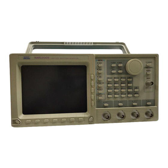
Tektronix AWG2005 Waveform Generator Manuals
Manuals and User Guides for Tektronix AWG2005 Waveform Generator. We have
2
Tektronix AWG2005 Waveform Generator manuals available for free PDF download: User Manual, Service Manual
Tektronix AWG2005 User Manual (608 pages)
Arbitrary Waveform Generator
Brand:
Tektronix
| Category:
Test Equipment
| Size: 8 MB
Table of Contents
Table of Contents
6
List of Figures
17
List of Tables
27
General Safety Summary
29
Product Damage Precautions
30
Safety Terms and Symbols
31
Terms in this Manual
31
Terms on the Product
31
Certifications and Compliances
32
Related Manuals
33
Contacting Tektronix
34
Getting Started
35
Product Description
37
Initial Inspection
38
Installation
39
Figure 1 1: Rear Panel Controls Used in Start
41
Figure 1 2: Optional Power Cords
42
Start up Diagnostics
43
Figure 1 3: ON/STBY Switch
43
Power off
44
Operating Basics
45
Figure 2 1: Front Panel Overall View
49
Figure 2 2: Front Panel Button Detail
51
TRIGGER INPUT Connector
54
Figure 2 3: Side Panel
55
Figure 2 4: Rear Panel Overall View
56
Figure 2 5: Rear Panel Detail
58
Figure 2 6: CRT Display
60
Basic Menu Operation
63
Figure 2 7: Menu Buttons and Bezel Buttons
63
Menu Names
64
Numeric Input
64
Figure 2 8: Numeric Input Using Numeric Keys
65
Figure 2 9: Numeric Keys, Unit Keys, Delete Key, and ENTER Key
66
Table 2 1: Numeric Value Input Example 1
66
Table 2 2: Numeric Value Input Example 2
67
Figure 2 10: General Purpose Knob and Arrow Buttons
68
Figure 2 11: Knob Icon and Underscore
68
Necessary Equipment
71
Operating Examples
71
Example 1: Setting the Date & Time and Adjusting the Brightness
72
Setting the Date and Time
72
Figure 2 12: Menu Display (Showing Date/Time Item Selected)
72
Date/Time Display
74
Figure 2 13: Date/Time Display
74
Setting the Display Brightness
75
Figure 2 14: Setting the Display Brightness
75
Loading Sample Waveforms
76
Figure 2 15: Inserting the Floppy Disk
76
Figure 2 16: Sample Waveform Library Disk Files
77
Figure 2 17: CRT Screen Display When Load All Is Selected
78
Setting the Output Parameters
79
Figure 2 19: Waveform File List
80
Figure 2 20: GAUSS_P .WFM File Output Parameters
81
Waveform Output
82
Figure 2 22: Connections in Example 2
82
Figure 2 23: Channel On/Off Buttons and Indicators
83
Example 3: Creating Files and Arbitrary Waveform Outputs
84
Creating a Waveform File
84
Figure 2 24: Initial Menu
84
Figure 2 25: Waveform Editor Graphic Menu
85
Figure 2 26: Setting the Point Value for the Right Side Vertical Bar Cursor
86
Figure 2 27: Creating a Sine Waveform
87
Figure 2 28: Creating a Ramp Waveform
88
Figure 2 29: Naming a File
89
Creating Arbitrary Waveforms Using the Point Draw Function
90
Figure 2 30: Initial Menu File List
90
Figure 2 31: Entering a Name for the Copied File
91
Figure 2 32: Setting the Edit Range
92
Figure 2 33: Drawing a Waveform Using the Point
93
Creating Waveforms Arithmetically
94
Figure 2 34: Connecting the Points
94
Figure 2 35: Creating a Sine Wave
95
Figure 2 36: Sine Wave with Noise Added
96
Creating an Equation File
97
Figure 2 37: Equation Editor Menu Display
97
Figure 2 38: Equation List Input
98
Figure 2 39: Display of Compiled Waveform Data
99
Creating a Sequence File
100
Figure 2 40: Initial Menu File List
100
Figure 2 41: Sequence Editor Menu Display
101
Figure 2 42: Sequence Example
102
Figure 2 43: Sequence Waveform Display with Show
103
Creating Autostep Files
104
Figure 2 44: Moving the Cursor
104
Figure 2 45: File List
105
Figure 2 46: Setting Files
105
Figure 2 47: Setting the Files for Step 1
106
Figure 2 48: Step 2 Display
106
Figure 2 49: Setting the Files for Step 2
107
Setting the Output Parameters
108
Figure 2 51: Setting Output Parameters
109
Setting Operation Mode and Waveform Output
110
Figure 2 52: Connections for Example 3
110
Continuous Mode
110
Figure 2 53: MODE Menu
111
Figure 2 54: Setting the Marker Default
112
Figure 2 55: Menu Displayed When Triggered Is Selected
113
Figure 2 56: MANUAL Button and TRIGGER INPUT Connector
113
Figure 2 57: Menu Displayed When Autostep Is Selected
114
Figure 2 58: Autostep File List
115
Example 4: Loading and Saving Files
116
Saving Files
116
Figure 2 59: SAVE Menu
117
Loading Files
118
Figure 2 60: Files Saved in Nvram
118
Figure 2 61: Internal Memory File List
119
Auto Load
120
Figure 2 62: Files Loaded into Internal Memory
120
Example 5: Loading Waveforms from Other Instruments
122
Figure 2 63: Connections for Example 5
122
Figure 2 64: DSO Screen
123
Figure 2 65: Confirmation Message (Asking if It Is O.K. to Change the Remote Port and GPIB Configuration Settings)
123
Figure 2 66: GPIB Source List
124
Example 6: Using the Waveform Function Generator
126
CH1 Waveform Settings
126
Figure 2 67: Screen When Sine Set for CH1
126
CH2 Waveform Setting
128
Figure 2 68: CH1 Output Parameter Setting Display
128
Figure 2 69: CH2 Output Parameter Setting Display
129
Waveform Output
130
Figure 2 70: Connections for Example 6
130
Functional Operation
131
Introduction
133
Block Diagram
135
Figure 3 1: Block Diagram
135
Clock Generator
136
Figure 3 2: Clock Generator
136
Figure 3 3: Connecting Three AWG2005 Instruments in Parallel
138
Figure 3 4: Waveform Timing
139
Clock Generator (Option 05: Clock Sweep)
140
Figure 3 5: Block Diagram of the Clock Generator (Option 05: Clock Sweep)
140
Sequence, Waveform Memory and D/A Converter
141
Figure 3 6: Block Diagram of the Sequence, Waveform Memory and D/A Converter
141
Sequence
142
Table 3 1: Sample Sequence Files
142
Waveform Memory
143
D/A Converter
143
Data Length
143
Figure 3 7: Relationship between Triangular Wave Resolution and Number of Data Points
143
Digital Data Output (Option 04)
144
Analog Circuit
145
Filter
145
Figure 3 8: Block Diagram of the Analog Circuit
145
Multiplier
146
Figure 3 9: 100% Amplitude Modulation
146
Table 3 2: Cutoff Frequencies and Delays
146
Table 3 3: Output Signals for External Signals
146
Variable Gain Amplifier/Attenuator
147
Output Amplifier
147
Offset
147
Table 3 4: CH1 Signal Output for CH2 Signal Amplitude
147
Introduction
151
EDIT Menu
153
General Description
153
Initial Menu
155
Initial Menu Structure
155
Figure 4A 1: Initial EDIT Menu Structure
155
Menu Functions
156
Table 4A 1: Menu Functions
156
CRT Display
157
Figure 4A 2: Display of the Initial Menu
157
Creating or Editing a File
158
Creating a New File
158
Editing an Existing File
159
Using File Editing Functions
159
Renaming a File
159
Figure 4A 3: Menu Displayed When Rename Is Selected
160
Comment Input
161
Copying a File
161
Deleting a File
161
Locking and Unlocking Files
162
Figure 4A 4: Menu Displayed When Delete Is Selected
162
Expanding a Sequence File into a Waveform File
163
Figure 4A 5: Menu Displayed When Lock Is Selected
163
Figure 4A 6: Menu Display When Expand SEQ into WFM Is Selected
164
Waveform Editor
165
Entering the Waveform Editor
165
Opening and Selecting Editing Areas
166
Figure 4A 7: Graphic CRT Display
166
Figure 4A 8: Waveform Editor with Three Editing Areas
167
Figure 4A 9: Menu Display When Another Waveform Is Selected
168
Figure 4A 10: Waveform2 Added
169
Figure 4A 11: Menu Display When Show Catalog Entry Is Selected
169
Figure 4A 12: Waveform3 Added
170
Saving Files and Exiting the Editor
171
Choices When Exiting the Editor
171
Naming a File
172
Figure 4A 13: Menu with File Name
172
Graphic Display
174
Graphic Display Menu Structure
174
Figure 4A 14: Waveform Editor Graphic Display Menu Structure
176
Menu Functions
177
Table 4A 2: Menu Functions
177
Graphic Display Screen
178
Figure 4A 15: Graphic Display Screen
178
Settings for the Waveform to be Edited
180
Selecting the Waveform Data Display Format
180
Setting Waveform Point Count
181
Setting Horizontal Axis Units
183
Figure 4A 16: Setting the Unit for the Horizontal Axis
183
Setting Clock Frequency
184
Figure 4A 17: Menu Displayed When Clock Is Selected
184
Linking the Vertical Bar Cursors
185
Displaying a Grid in the Editing Area
187
Figure 4A 19: Grid Set to on
187
Creating a Standard Function Waveform
188
Selecting Function Waveform Type and Calculation Method
188
Setting the Parameters for Function Waveforms
189
Procedure 1: Creating a Sine Wave
189
Procedure 2: Adding a Waveform to Existing Data
190
Figure 4A 20: Creating a Sine Wave
190
Figure 4A 21: Adding Noise to the Sine Wave
191
Procedure 3: Multiplying Waveforms
192
Figure 4A 22: Multiplying Sine Waves
192
Editing Waveforms in Graphic Display
193
Setting Editing Areas
193
Cutting Waveforms
194
Figure 4A 23: Defining the Editing Area
194
Copying/Pasting Waveforms
195
Figure 4A 24: Cutting Waveforms
195
Draw Function
197
Figure 4A 25: Pasting Waveforms
197
Figure 4A 26: Menu Display When Draw
198
Shift Function
200
Figure 4A 27: Smoothing
200
Figure 4A 28: Horizontally Shifted Display
202
Figure 4A 29: Vertically Shifted Display
202
Scaling Function
203
Figure 4A 30: Display Expanded Horizontally
204
Invert Function
205
Figure 4A 31: Display Expanded to X1.5 Vertically
205
Figure 4A 32: Horizontally Inverted Display
206
Clip Function
207
Figure 4A 33: Vertically Inverted Display
207
Setting a Marker
208
Figure 4A 34: Display of Waveform Clipped above Clip Level
208
Figure 4A 35: Marker Signal Set High
210
Inserting Other Waveforms
211
Figure 4A 36: Entering Pattern Data
211
Figure 4A 37: Defining the Location for Insertion
212
Figure 4A 38: List of Files for Insertion
213
Figure 4A 39: File Waveform Display
213
Single Waveform Calculations
214
Figure 4A 40: Inserting Waveforms
214
Figure 4A 41: Waveform Example before Calculation
215
Figure 4A 42: Absolute Calculation
216
Figure 4A 43: Square Calculation
216
Figure 4A 44: Cube Calculation
217
Figure 4A 45: Square Root Calculation
217
Figure 4A 46: Normalize Calculation
218
Figure 4A 47: Integral Calculation
218
Calculations with Other Waveform Data
219
Figure 4A 48: Differential Calculation
219
Figure 4A 49: Example of Waveform before Arithmetic
220
Figure 4A 50: List of Files for Waveform Calculation
221
Figure 4A 51: Selected File Waveform Display
221
Figure 4A 52: Waveform Addition Display
222
Specified Region Shift
223
Table 4A 3: Differences between the Shift Operations
223
Figure 4A 53: Data Shifted Using the "Right" Item
224
Figure 4A 54: Data Compressed Using the "Compress" Item
224
Figure 4A 55: Linear Interpolation
226
Figure 4A 56: Quadratic Interpolation
227
Figure 4A 57: Shift with "Cursor Point" Set to "Exclude
228
Figure 4A 58: Smoothing
229
Figure 4A 59: Data Shifting
229
Multiple Copy
230
Figure 4A 60: Increasing the Size of the Area
230
Figure 4A 61: Two Waveform Editing Areas Designated
231
Figure 4A 62: Setting the Copy Source
232
Figure 4A 63: Setting the Copy Destination
233
Figure 4A 64: Waveform Copying (Number of Points in Waveform = Interval Value)
234
Figure 4A 65: Waveform Copying (Number of Points in Waveform < Interval Value)
234
Convolution Calculations
235
Figure 4A 66: Waveform Copying (Number of Points in Waveform > Interval Value)
235
Figure 4A 67: Waveforms Used for Waveform1 and Waveform2
236
Comparing Waveforms
238
Figure 4A 68: Convolution
238
Figure 4A 69: Compare
240
Figure 4A 70: Comparison Without Hysteresis
241
Zooming Waveforms
242
Figure 4A 71: Comparison with Hysteresis
242
Horizontal Zooming
243
Figure 4A 72: Zoom Menu
243
Figure 4A 73: Horizontal Zoom
244
Vertical Zooming
245
Figure 4A 74: Vertical Zoom
245
Timing Display
246
Figure 4A 75: Timing Display
246
Timing Display Menu Structure
247
Figure 4A 76: Waveform Editor Timing Display Menu Structure
248
Menu Functions
249
Table 4A 4: Menu Functions
249
Timing Display Screen
250
Figure 4A 77: Timing Display Screen
250
Settings for the Waveform to be Edited
251
Creating Standard Waveform Data
251
Pattern Types
251
Figure 4A 78: Count up Pattern Display
252
Example of Waveform Data Creation
253
Figure 4A 79: Gray Code Pattern Display
253
Editing Waveform Data in Timing Display
254
Cut, Copy, and Paste Processing Function
254
Setting Waveform Data
254
Figure 4A 80: Setting Waveform Data to High/Low
255
Figure 4A 81: Pattern Data Setting Menu
256
Figure 4A 82: Setting Pattern Data
260
Figure 4A 83: User Defined Code Conversion Menu
261
Shifting Waveform Data
267
Inverting Waveform Data
268
Figure 4A 84: Shifting Waveform Data
268
Copying Lines
269
Figure 4A 85: Inverting Waveform Data State
269
Exchanging Lines
270
Figure 4A 86: Copying Lines
270
Applying Logical Operations to Lines
271
Figure 4A 87: Exchanging Lines
271
Expanding Waveform Data
272
Inserting Other Waveform Data
273
Pseudo Random Pulse Generator Using Shift Register
273
Figure 4A 88: Expanding Waveform Data
273
Figure 4A 89: Shift Register Configuration Menu
274
Figure 4A 90: Register Values and Taps
275
Figure 4A 91: Sample Settings for Register Values and Taps
276
Zooming Waveforms
279
Figure 4A 92: Table Display
279
Figure 4A 93: Waveform Editor Table Display Menu Structure
280
Menu Functions
281
Settings for the Waveform to be Edited
281
Setting a Cardinal Number
281
Table 4A 5: Menu Functions
281
Figure 4A 94: Table Display Screen
282
Editing Waveform Data
285
Figure 4A 95: Numeric Displays for Waveform Data
285
Editing Waveform Data in Table Display
286
Cut, Copy, and Paste Processing Function
286
Inserting Other Waveform Data
286
Equation Editor
287
Entering the Equation Editor
287
Figure 4A 96: Example of Equation File Data and
287
Saving Files and Exiting the Editor
288
Equation Editor Menu Structure
288
Figure 4A 97: Equation Editor Menu Structure
288
Menu Functions
289
Table 4A 6: Menu Functions
289
Equation Editor Menu Display
290
Figure 4A 98: Equation Editor CRT Display
290
Creating and Editing Equation Files
292
Specifying the Time Domain
292
Figure 4A 99: Menu with Operation Selected
292
Using the Front Panel Buttons in Editing
293
Decimal Point
294
Component Menu
294
Figure 4A 100: Component Menu
294
Figure 4A 101: Trigonometric Function Waveform
296
Figure 4A 102: Trigonometric Function Waveform Expressed with Variable T
297
Figure 4A 103: Equation Using Exp
297
Figure 4A 104: Equation Using Log
298
Figure 4A 105: Equation Using Ln
298
Figure 4A 106: Equation Using Sqrt
299
Figure 4A 107: Equation Using Abs
299
Figure 4A 108: Equation Using Int
300
Figure 4A 109: Equation Using Round
300
Figure 4A 110: Equation Using Norm
301
Figure 4A 111: Equation Using Max
301
Figure 4A 112: Equation Using Rnd
302
Figure 4A 113: Waveform before Calculation
303
Figure 4A 114: Waveform after Differentiation Using Diff
303
Figure 4A 115: Waveform after Integration Using Integ
304
Editing Functions
305
Cutting a Line
305
Copying and Pasting a Line
305
Insert Other Equation File
306
Figure 4A 116: Menu Displayed When Insert Other Equation Is Selected
306
Setting Waveform Point Count
307
Figure 4A 117: Setting Waveform Point Count
307
Compiling Equations into Waveform Data
308
Figure 4A 118: Example of Compiled Waveform Display
308
Sequence Editor
310
Figure 4A 119: Sequence File Data and Sample
310
Entering the Sequence Editor
311
Saving Files and Exiting the Editor
311
Sequence Editor Menu Structure
312
Menu Functions
312
Figure 4A 120: Sequence Editor Menu Structure
312
Table 4A 7: Menu Functions
312
Sequence Editor Menu Display
313
Figure 4A 121: Sequence Editor CRT Display
313
Creating and Editing Sequence Files
315
Creating a Sequence File
315
Button Functions
316
Figure 4A 122: Sequence File Creation Example
316
Editing Functions
317
Cutting a Line
317
Copying and Pasting a Line
317
Catalog File Waveform Display
318
Figure 4A 123: Example of Waveform Display When Show Catalog Entry Is Selected
318
Inserting a Sequence File
319
Sequence File Display
319
Figure 4A 124: Example of CRT Display When Show Overview Is Selected
320
Autostep Editor
321
Figure 4A 125: Autostep File Data and Output Waveforms
321
Entering the Autostep Editor
322
Saving Files and Exiting the Editor
322
Autostep Editor Menu Structure
323
Figure 4A 126: Autostep Editor Menu Structure
323
Menu Functions
324
Table 4A 8: Menu Functions
324
Autostep Editor Menu Display
325
Figure 4A 127: Autostep Editor CRT Display
325
Creating and Editing Autostep Programs
327
Setting Files
327
Figure 4A 128: Selecting the Item for File Setting
327
Figure 4A 129: File Selection List
328
Figure 4A 130: Sample File Waveform Display
328
Figure 4A 131: Setting a File
329
Changing Parameters
330
Clock Settings
331
Figure 4A 132: Clock Setting Menu
331
CH1 Operation Settings
332
Figure 4A 133: CH1 Operation Setting Menu
332
Filter Settings
333
Figure 4A 134: Filter Setting Menu
333
Amplitude Settings
334
Figure 4A 135: Amplitude Setting Menu
334
Offset Settings
335
Figure 4A 136: Offset Setting Menu
335
Editing Functions
336
Cutting a Step
336
Copying and Pasting a Step
336
Adding a Step
337
Inserting the SETUP Menu Waveforms and Output Parameters
337
Swapping Steps between Channels
337
Jumping to a Step
338
Clock Sweep Editor (Option 05)
339
Entering the Clock Sweep Editor
339
Saving Files and Exiting the Editor
339
Figure 4A 137: Sample Linear Up/Down Clock
339
Clock Sweep Editor Menu Structure
340
Figure 4A 138: Clock Sweep Editor Menu Structure
340
Menu Functions
341
Table 4A 9: Menu Functions
341
Clock Sweep Editor Menu Display
342
Figure 4A 139: Clock Sweep Editor CRT Display
342
Settings for Editing Clock Sweep Data
344
Setting the Number of Steps
344
Setting the y Axis Scale
345
Setting the Horizontal Unit
345
Figure 4A 140: y Axis Scale Settings
345
Setting the Dwell Time
346
Figure 4A 141: Horizontal Unit Settings
346
Creating a Standard Clock Sweep Waveform
347
Setting the Parameters and Type of Standard Clock Sweep
347
Figure 4A 142: Sample Linear Clock Sweep
347
Figure 4A 143: Sample Log Clock Sweep
348
Figure 4A 144: Sample Linear U/D Clock Sweep
348
Figure 4A 145: Sample Log U/D Clock Sweep
349
Figure 4A 146: Sample Constant Clock Sweep
349
Setting Parameters for Clock Sweep Waveform
350
Figure 4A 147: Duty for U/D Clock Sweep
350
Sample Creation of a Linear U/D Clock Sweep
351
Figure 4A 148: Creating a Linear U/D Clock Sweep
351
Editing Clock Sweep Data
352
Setting Editing Areas
352
Cutting, Copying and Pasting Data
352
Draw Function
352
Setting Hold Bits
353
Figure 4A 149: Connecting Points
353
Figure 4A 150: Hold Bit Set at Active Vertical Bar Cursor
354
Zooming Clock Sweep Waveforms
355
Figure 4A 151: Hold Bits Set between Vertical Bar Cursors
355
Convolution Waveform Editor (Option 09)
356
Entering the Convolution Waveform Editor
356
Saving Files and Exiting the Editor
357
Convolution Waveform Editor Menu Structure
357
Menu Functions
357
Figure 4A 152: Convolution Waveform Editor Menu Structure
357
Table 4A 10: Menu Functions
357
Convolution Waveform Editor Menu Display
358
Figure 4A 153: Convolution Waveform Editor CRT Display
358
Selecting a Waveform File
359
Figure 4A 154: Selecting a Waveform File
359
Executing Convolution/Correlation
360
Figure 4A 155: Sample Convolution
360
Figure 4A 156: Sample Correlation
361
FFT Editor (Option 09)
362
Entering the FFT Editor
362
Figure 4A 157: FFT Window Selection Menu
363
Saving Files and Exiting the Editor
364
FFT Editor Menu Structure
364
Figure 4A 158: FFT Editor Menu Structure
364
Menu Functions
365
Table 4A 11: Menu Functions
365
FFT Editor Menu Display
366
Figure 4A 159: FFT Editor CRT Display
366
Editing in the Frequency Domain
368
Editing Magnitude
368
Editing Phase
369
Searching for Peaks
369
Drawing Magnitude and Phase
369
Figure 4A 161: Drawing a Magnitude
372
Magnifying a Signal
373
Figure 4A 162: Magnified Signal Display
373
Selecting a Filter
374
Figure 4A 163: Low Pass Filter
374
Figure 4A 164: High Pass Filter
374
Figure 4A 165: Band Pass Filter
375
Figure 4A 166: Band Cut Filter
375
Selecting a Limiter
376
Cutting Extraneous Frequency Components
376
Deleting Even or Odd Components
376
Shifting Magnitudes
377
Figure 4A 167: Fundamental, Odd, and Even Components
377
SETUP Menu
379
General Description
379
SETUP Menu Structure
380
Figure 4B 1: SETUP Menu Structure
380
Menu Functions
381
SETUP Menu Display
381
Figure 2 18: SETUP Menu
381
Figure 4B 2: SETUP Menu (Graphic Mode)
381
Table 4B 1: Menu Functions
381
Selecting the Display Format for the SETUP Menu
383
Figure 4B 3: SETUP Menu (Text Mode)
383
Selecting Output Parameter Fields
384
Numeric Input
384
Selecting a Waveform or Sequence File
385
Setting Clock Source and Frequency
387
Figure 4B 4: Clock and Waveform Points
387
CH1 Waveform Operations
389
Figure 4B 5: Multiplying CH1 Waveform by CH2 Waveform
390
Figure 4B 6: Adding CH1 Waveform and CH2 Waveform
391
Figure 4B 7: Multiplying CH1 Waveform by an External Waveform
392
Table 4B 2: Output Signal Amplitude Relative to External
392
Figure 4B 8: Adding CH1 Waveform and External Waveform
393
Setting Filter
394
Setting Amplitude and Offset
394
Figure 4B 9: Amplitude and Offset Setting
394
Setting Amplitude
395
Setting Offset
395
Linking the CH1 Waveform and Amplitude or Offset
396
Setting Clock Sweep (Option 05)
397
Figure 4B 10: Clock Menu Item with Sweep Set to on
397
Setting the Sweep Type
399
Setting the Sweep Type to Linear or Log
400
Figure 4B 12: Linear Clock Sweep Waveform
400
Setting Sweep Type to Arbitrary
401
Figure 4B 13: Sample Linear and Log Clock Sweep Settings
401
Figure 4B 14: Arbitrary Clock Sweep Waveform
401
Figure 4B 15: Clock Sweep File List
402
Setting the Sweep Mode
403
Figure 4B 16: Sample Arbitrary Clock Sweep Setting
403
Stopping the Sweep
404
MODE Menu
405
General Description
405
MODE Menu Structure
406
Figure 4C 1: MODE Menu Structure
406
Menu Functions
407
Table 4C 1: Menu Functions
407
MODE Menu Display
408
Figure 4C 2: MODE Menu CRT Display
408
Setting the Operating Mode
409
Cont Mode
410
Triggered Mode
410
Figure 4C 3: Output Waveform for External Trigger Signal in Triggered Mode
410
Gated Mode
411
Figure 4C 4: Output Waveform for External Gate Signal in Gated Mode
411
Waveform Advance Mode
412
Waveform Output Conditions
412
Figure 4C 5: Waveform Output in Response to External Trigger Signal (When Run Is Set to Continuous and Step)
413
Autostep Mode
414
Waveform Output Conditions
414
Figure 4C 6: Waveform Output in Response to External Trigger Signal (When Run Is Set to Continuous and Step)
415
Starting an Autostep Program
416
Figure 4C 7: Autostep File List
416
Setting Trigger Parameters for an External Trigger (Gate)
417
Figure 4C 8: Slope and Level Controls
417
Designating the System as Master or Slave
418
Figure 4C 9: AWG2005 Parallel Operation
418
LOAD/SAVE Menu
419
General Description
419
Memory Capacity
420
Figure 4D 1: Relationship between Memory and Execution of Load/Save
420
LOAD/SAVE Menu Structure
421
Menu Functions
421
Figure 4D 2: LOAD/SAVE Menu Structure
421
Table 4D 1: Menu Functions
421
LOAD Menu Display
422
Figure 4D 3: LOAD Menu CRT Screen Display
422
Selecting the Device
424
Table 4D 2: Supported Instruments
425
Loading Files from Mass Memory into Internal Memory
426
Figure 4D 4: LOAD Menu
426
Saving Files from Internal Memory to Mass Memory
428
Figure 4D 5: SAVE Menu
428
Saving Data in Text Format
429
Transferring Waveform Data Directly
430
Loading Waveform Data
430
Figure 4D 6: Connecting Instruments
430
Figure 4D 7: GPIB Source List
431
Selecting Instruments Made by Other Manufacturers
432
Figure 4D 8: List of Supported Models Made by Other
432
Auto Loading
433
Supported Floppy Disk Files
434
Table 4D 3: Supported Floppy Disk Files
434
UTILITY Menu
435
General Description
435
UTILITY Menu Structure
436
Figure 4E 1: UTILITY Menu Structure
436
Menu Functions
437
Table 4E 1: Menu Functions
437
Disk and Nonvolatile Memory
438
Using the Disk Menu
438
Floppy Disk Format
438
Figure 4E 2: Format
439
Table 4E 2: MS DOS Formats for 3.5 Inch Disks
440
Handling Floppy Disks
441
Protecting Disks from Accidental Erasure
441
Creating and Changing Directories
442
Figure 4E 3: Write Protect Tab on a Floppy Disk
442
Root Directory
443
Figure 4E 4: File and Directory Display in the Root Directory
444
Figure 4E 5: Directory Name Input
444
Figure 4E 6: Directory Displayed When Change Directory Is Selected
445
Operating Files Saved to Disk
446
Locking and Unlocking a File
446
Figure 4E 7: File List for a Newly Created Directory
446
Internal Non Volatile Memory
447
Figure 4E 8: Menu Displayed When Nvram Is Selected
447
Remote Interface
448
Gpib
448
GPIB Connection
448
Setting GPIB Configuration
448
Figure 4E 9: Menu Displayed When GPIB Is Selected
448
Rs 232 C
449
RS 232 C Connection
449
Setting the RS 232 C Parameters
450
Figure 4E 10: Menu Displayed When RS232C Is Selected
450
Date and Time
452
Setting the Date and Time
452
Figure 4E 11: Menu Displayed When Date Time Is Selected
452
Other Settings and Displays
453
Setting the Display
453
Setting the Display Brightness
454
Figure 4E 12: Setting the Display Brightness
454
Setting the Order of Files
455
Figure 4E 13: Menu Displayed When Catalog Order Is Selected
455
Figure 4E 14: Catalog Files
456
Figure 4E 15: Catalog with Files Displayed in Type4 Format
457
Date/Time Display
458
Configuration
458
Factory Settings
458
Figure 4E 16: Date/Time Display
458
Deleting Data from Memory
459
Remote Port Settings
460
Settings for Hard Copy Output
460
Selecting the Format
460
Selecting the Port
461
Figure 4E 17: Format Selection Menu
461
Figure 4E 18: Port Selection Menu
461
Table 4E 3: Format Extensions
461
Status Display
463
System and GPIB/RS 232 C Status
463
Figure 4E 19: Menu Displayed When System Is Selected
463
I/O Event Reporting
464
Figure 4E 20: I/O Event Reporting
464
Diagnostics and Calibrations
465
Diagnostics
465
Figure 4E 21: Diagnostics List
465
Calibrations
466
Pattern Display (for Instrument Adjustment)
467
Figure 4E 22: Calibration List
467
Function Waveform Generator Mode
469
General Description
469
Table 4F 1: Number of Data Points for Frequencies and Marker
469
Function Generator Menu Structure
470
Figure 4F 1: FG Mode Menu Structure
470
Function Generator Menu Display
471
Figure 4F 2: FG Mode Menu Display
471
Setting the Output Waveform
472
Selecting the Channel
472
Selecting the Waveform
472
Setting the Output Parameters for the Waveform
473
Setting the Frequency
473
Setting the Amplitude
473
Figure 4F 3: Setting the Amplitude
473
Setting the Offset
474
Setting the Polarity
474
Figure 4F 4: Setting the Offset
474
Figure 4F 5: Waveform Polarity
474
Setting the Duty
475
Marker Output
475
Figure 4F 6: Setting the Duty Value for a Pulse Wave
475
Appendices
477
Appendix A: Options and Accessories
479
Options
479
Advertisement
Tektronix AWG2005 Service Manual (231 pages)
Arbitrary Waveform Generator
Brand:
Tektronix
| Category:
Portable Generator
| Size: 4 MB
Table of Contents
Table of Contents
8
List of Figures
14
List of Tables
18
General Safety Summary
20
Service Safety Summary
24
Adjustment Interval
26
Introduction
26
Strategy for Servicing
26
Tektronix Service Offerings
26
Repair or Calibration Service
27
Self Service
27
Warranty Repair Service
27
Product Description
28
Nominal Traits
30
Table 1 1: Period Jitter (CH1 Marker Out)
34
Table 1 2: Cycle to Cycle Jitter (CH1 Marker Out)
34
Table 1 3: Period Jitter (Clock Out)
34
Table 1 4: Cycle to Cycle Jitter (Clock Out)
34
Performance Conditions
38
Warranted Characteristics
38
Typical Characteristics
46
Operating Environment
50
Operating Temperature
50
Preparation for Use
50
Ventilation Requirements
50
Power Cord Information
51
Supplying Power
51
Table 2 1: Power Cord Conductor Identification
51
Figure 2 1: Optional Power Cords
52
Rear Panel Controls
52
Figure 2 2: Rear Panel Controls
53
Fuse Type and Rating
53
Table 2 2: Fuse Type and Rating
53
Applying and Interrupting Power
54
Power off Cycle
54
Power on Cycle
54
Installed Options
55
Memory Backup Power
55
How to Power on
56
Instructions for Operation
56
Internal Diagnostics Routines
56
Display
57
User Interface
57
Figure 2 3: Display Features
59
Menus
60
Waveform Files
60
Loading Files
61
Waveform Storage and I
61
Figure 2 4: LOAD Menu
62
Setting Output Parameters
62
Figure 2 5: SETUP Menu
63
Operation Mode Settings
64
Figure 2 6: MODE Menu
65
Clock Oscillator (A1 Clock Board)
68
Clock Sweep Oscillator (A31 Clock Sweep Board)
68
Module Overview
68
Sequencer (A2 AWG Board)
68
Theory of Operation
68
Waveform Memory (A2 AWG Board)
68
Analog Processing (A3/A23 Analog Board)
69
CPU and Memory (A6 CPU Board)
69
Digital to Analog Converter (DAC) (A11 D/A Board)
69
Display Control (A6 CPU Board)
69
GPIB (A6 CPU Board)
69
RS 232 C (A6 CPU Board)
69
Display Monitor
70
Fan
70
Floppy Disk Drive
70
Front Panel (A12 Key Board)
70
Low Voltage Power Supply
70
Options
71
Before Verification
72
Conventions
72
Preparation
72
Diagnostics
74
Self Tests
74
Figure 4 1: Diagnostics Menu
75
Calibration
76
Figure 4 2: Calibrations Menu
77
Performance Tests
78
Prerequisites
78
Equipment Required
79
Related Information
79
Table 4 1: Test Equipment
79
Performance Check Files
80
Table 4 2: Test Equipment for Optional Check
80
Table 4 3: File List for Performance Check Disk
81
Check Cont Mode
83
Figure 4 3: Cont Mode Initial Test Hookup
83
Operating Mode Checks
83
Check Triggered Mode
85
Figure 4 4: Triggered Mode Initial Test Hookup
85
Check Gated Mode
87
Figure 4 5: Gated Mode Initial Test Hookup
87
Check Waveform Advance Mode
89
Figure 4 6: Relationship between 1 Volt or Greater Gate Signal and Waveform Output Signal
89
Figure 4 7: Waveform Advance Mode Initial Test Hookup
90
Check Autostep Mode
91
Figure 4 8: Autostep Mode Initial Test Hookup
92
Arithmetic Operation Checks
93
Check External am Operation
93
Figure 4 9: External am Operation Initial Test Hookup
94
Figure 4 10: MODE Menu Autostep Setting
95
Check External ADD Operation
96
Check Internal am Operation
96
Check Internal Add Operation
97
Check Clock Frequency Accuracy
98
Clock Frequency and Amplitude Checks
98
Figure 4 11: Clock Frequency Accuracy Initial Test Hookup
98
Check Clock Amplitude
100
Figure 4 12: Clock Amplitude Initial Test Hookup
100
Table 4 4: Clock Frequency Accuracy
100
Gain Accuracy Check
101
Figure 4 13: Gain Accuracy Initial Test Hookup
102
Offset Accuracy Check
103
Figure 4 14: Offset Accuracy Initial Test Hookup
104
Figure 4 15: Pulse Response Initial Test Hookup
105
Pulse Response Check
105
Figure 4 16: Initial Test Hookup
107
MARKER out Amplitude Check
107
CONTROL SIG out Amplitude Check
109
Figure 4 17: Initial Test Hookup
109
External Trigger Level Accuracy Check
110
Figure 4 18: External Trigger Level Accuracy Initial Test Hookup
111
External CLOCK in Check
113
Figure 4 19: External CLOCK in Initial Test Hookup
113
Figure 4 20: Slave Operation Initial Test Hookup
115
Optional Check - Master Slave Operation Check
115
DIGITAL DATA out Check (Option 04)
117
Figure 4 21: Digital Data out Initial Test Hookup
118
Figure 4 22: Output Pins on the Digital Data out Cable
119
Floating Point Processor Check (Option 09)
120
Adjustments
122
Before Maintenance
124
Prerequisites
124
Precautions
125
Preventing ESD
125
Susceptibility to ESD
125
Table 6 1: Relative Susceptibility to Static Discharge Damage
126
General Care
128
Inspection and Cleaning
128
Inspection and Cleaning Procedures
128
Inspection Exterior
129
Table 6 2: External Inspection Check List
129
Cleaning Procedure Exterior
130
Inspection Interior
130
Table 6 3: Internal Inspection Check List
130
Cleaning Procedure Interior
131
Lubrication
131
List of Mechanical Parts
132
Preparation
132
Removal and Installation Procedures
132
Equipment Required
133
General Instructions
133
Summary of Procedures
133
Table 6 4: Equipment Required
134
AWG2005 Orientation
135
Figure 6 1: AWG2005 Orientation
135
Access Procedure
136
Figure 6 2: Guide to Removal Procedures
136
Figure 6 3: External Modules
137
Figure 6 4: Internal Modules
138
Procedures for External Modules
139
Figure 6 5: Front Panel Knob Removal
140
Front Panel Knob
140
Line Fuse and Line Cord
141
Figure 6 6: Line Fuse and Line Cord Removal
142
Rear Cover and Cabinet
143
Figure 6 7: Rear Cover and Cabinet Removal
144
EMI Gaskets
145
Front Cover, Trim Ring, and Menu Buttons
145
Figure 6 8: Front Cover, Trim Ring, and Menu Button Removal (Front Cover Not Shown)
146
Front Panel Module
147
Figure 6 9: Front Panel Module Removal
148
Figure 6 10: A12 Keyboard Removal
149
Figure 6 11: Disassembly of Front Panel Module
150
Procedures for Internal Modules
151
A23 Analog Board or A3 Analog Board (Option 02)
152
Figure 6 12: A23/A3 Analog Board Removal
153
Connector Module
154
Figure 6 13: Connector Module Removal
155
Fan and Fan Frame
156
Figure 6 14: Fan and Fan Frame Removal
157
Rear Shield Cover
158
Figure 6 15: Rear Shield Cover Removal
159
Figure 6 16: Rear BNC Connectors Removal
160
Rear BNC Connectors
160
Power Supply Module
161
AUX Power Board and AC Inlet
162
Figure 6 17: Power Supply Module Removal
162
Figure 6 18: aux Power Board and AC Inlet Removal
164
Monitor Module and CRT Frame
165
Figure 6 19: Monitor Module Removal
166
Figure 6 20: CRT Frame Removal
167
Circuit Boards
168
Figure 6 21: Board Removal
169
A5 Backplane Board
172
Figure 6 22: A5 Backplane Board Removal
173
Lithium Battery
174
Figure 6 23: Battery Location on the A5 Backplane Board
175
Floppy Disk Drive Module
176
Figure 6 24: Floppy Disk Drive Module Removal
177
Repackaging
178
Repackaging Instructions
178
Figure 6 25: Primary Troubleshooting Procedure
180
Figure 6 27: Troubleshooting Procedure 1
180
Figure 6 30: Troubleshooting Procedure 2
180
Figure 6 32: Troubleshooting Procedure 3
180
Troubleshooting
180
Troubleshooting Procedures
180
AWG2005 Diagnostics
181
Checking Diagnostics Tests
181
Figure 6 26: CPU Board
183
Figure 6 28: aux Power Board
185
Figure 6 29: Power Supply Module
185
Figure 6 31: Key Board
187
Figure 6 33: Monitor Module
189
Figure 6 34: Horizontal and Vertical Sync Signals
189
Figure 6 35: a Video Signal with White and Black Levels
190
Figure 6 36: Troubleshooting Procedure 4 Module Isolation
191
List of Options
192
Options and Accessories
192
Table 7 1: International Power Cords
193
Figure 7 1: Option 04 Block Diagram
194
Figure 7 2: Option 04 Output Connector
194
Table 7 2: Option 04 Digital Output Signals
195
Figure 7 3: Generation of Excess Output
196
Figure 7 4: Output Circuit
196
Figure 7 5: Output Waveform
197
Figure 7 6: Data Latching
197
Figure 7 7: Digital Data out Cable
198
Figure 7 8: Waveform Reproduction Circuit Example
199
Table 7 3: Standard Accessories List
201
Table 7 4: Optional Accessories List
201
Table 7 5: Maintenance Kit Contents
202
Options
203
Figure 9 1: Block Diagram
208
Option 02
208
Option 04
208
Figure 9 2: Interconnect Diagram
210
Figure 10 1: Cabinet
216
Figure 10 2: Main Chassis and CRT
218
Figure 10 3: Main Chassis and Circuit Boards
220
Figure 10 4: Circuit Boards
222
Figure 10 5: Front Panel Assembly
224
Figure 10 6: Option 02
226
Figure 10 7: Option 04
227
Figure 10 8: Option 05
228
Figure 10 9: Option 09
229
Advertisement
Related Products
Tektronix AWG 2021
Tektronix AWG 2000 Series
Tektronix AWG2020
Tektronix AWG7052
Tektronix AWG7082C
Tektronix AWG5014C
Tektronix AWG5012C
Tektronix AWG7062B
Tektronix AWG5014
Tektronix AWG410
Tektronix Categories
Test Equipment
Measuring Instruments
Amplifier
Portable Generator
Printer
More Tektronix Manuals
Login
Sign In
OR
Sign in with Facebook
Sign in with Google
Upload manual
Upload from disk
Upload from URL