Sign In
Upload
Manuals
Brands
TDK-Lambda Manuals
Power Supply
GENESYS 1500W
TDK-Lambda GENESYS 1500W Power Supplies Manuals
Manuals and User Guides for TDK-Lambda GENESYS 1500W Power Supplies. We have
2
TDK-Lambda GENESYS 1500W Power Supplies manuals available for free PDF download: User Manual, Technical Manual
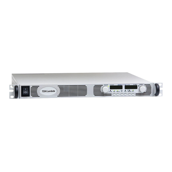
TDK-Lambda GENESYS 1500W User Manual (101 pages)
Programmable DC Power Supplies
Brand:
TDK-Lambda
| Category:
Power Supply
| Size: 1.93 MB
Table of Contents
Table of Contents
5
Warranty
11
English Safety Instructions
12
Safety Instructions
13
Francais (French) Safety Instructions
15
Consignes de Securite
15
Deutsch (German) Safety Instructions
18
Italiano (Italian) Safety Instructions
21
Norme DI Sicurezza
21
Portugues (Portugese) Safety Instructions
24
Español (Spanish) Safety Instructions
27
General Information
30
User Manual Content
30
Introduction
30
General Description
30
Models Covered by this Manual
30
Features and Options
31
Multiple Output Power System
31
Control Via the Serial Communication Port
31
Analog Voltage Programming and Monitoring
32
Parallel Operation
32
Output Connections
32
Cooling and Mechanical Construction
32
Accessories
33
Included Accessories
33
AC Cables
33
Hardware (Delivered with Power Supply)
33
Optional Communication Cables
33
Serial Link Cable
33
Specifications
34
Output Rating
34
Input Characteristics
34
Constant Voltage Mode
34
Constant Current Mode
34
Analog Programming and Monitoring
34
Programming and Readback
35
Protective Funcitions
35
Front Panel
35
Environmental Conditions
35
Mechanical
35
Safety/Emc
35
Supplemental Characteristics
36
Genesys ™ Outline Drawings
37
Installation
38
General
38
Preparation for Use
38
Initial Inspections
38
Rack Mounting
39
To Install the Power Supply in a Rack
39
Rack Mount Slides (Optional)
39
Location, Mounting and Cooling
39
AC Source Requirements
39
AC Input Power Connection
40
AC Input Connector, 1500W Models
40
AC Input Connector, 750W Models
40
AC Input Cord
40
AC Input Wire Connection, 1500W Models
41
Turn-On Checkout Procedure
41
General
41
Prior to Operation
42
Constant Voltage Check
42
Constant Current Check
42
OVP Check
42
UVL Check
43
Foldback Check
43
Address Setting
43
Baud Rate Setting (RS232 and RS485 Only)
43
Connecting the Load
44
Load Wiring
44
Current Carrying Capacity
44
Wire Termination
45
Noise and Impedance Effects
45
Inductive Loads
45
Making the Load Connections
46
Connecting Single Loads, Local Sensing (Default)
48
Connecting Single Loads, Remote Sensing
49
Connecting Multiple Loads, Radial Distribution Method
49
Multiple Load Connection with Distribution Terminals
50
Grounding Outputs
50
Local and Remote Sensing
50
Sense Wiring
50
Local Sensing
51
Remote Sensing
51
J2 Sense Connector Technical Information
52
Repackaging for Shipment
52
Front and Rear Panel Controls and Connectors
53
Introduction
53
Front Panel Controls and Indicators
53
Rear Panel Connections and Controls
55
Rear Panel SW1 Setup Switch
56
SW1 Position Function
57
Resetting the SW1 Switch
57
Rear Panel J1 Programming and Monitoring Connector
57
Making J1 Connections
58
Local Operation
60
Introduction
60
Standard Operation
60
Constant Voltage Mode
60
Constant Current Mode
61
Automatic Crossover
61
Over Voltage Protection (OVP)
61
Setting the OVP Level
61
Activated OVP Protection Indications
62
Resetting the OVP Circuit
62
Under Voltage Limit (UVL)
62
Setting the UVL Level
62
Foldback Protection
62
Setting the Foldback Protection
62
Resetting Activated Foldback Protection
62
Output ON/OFF Control
63
Output Shut-Off (SO) Control Via Rear Panel J1 Connector
63
Enable/Disable Control Via Rear Panel J1 Connector
64
CV/CC Signal
64
PS_OK Signal
64
Safe-Start and Auto-Restart Modes
65
Auto-Restart Mode
65
Safe-Start Mode
65
Over Temperature Protection (OTP)
65
Last Setting Memory
65
Series Operation
66
Series Connection for Increased Output Voltage
66
Series Connection for Positive and Negative Output Voltage
67
Parallel Operation
68
Basic Parallel Operation
68
Setting up the Master Unit
68
Setting up the Slave Units
68
Advanced Parallel Operation
69
Connection to the Load
69
Daisy Chain Connection: (See Fig. 5-6)
69
Setting Foldback Protection
69
Setting over Voltage Protection
69
Advanced Parallel Configuration
70
Master and Slave Units Default Operation
70
Setting the Units as Master or Slave
70
CURRENT Display Accuracy
71
To Release Units from Slave Mode
71
Daisy-Chain Connection
72
Front Panel Locking
72
Unlocked Front Panel
72
Locked Front Panel
73
Remote Analog Programming
74
Introduction
74
Local/Remote Analog Indication
74
Remote Voltage Programming of Output Voltage and Output Current
75
Resistive Programming of Output Voltage and Current Limit
76
Remote Monitoring of Output Voltage and Current
77
Rs232 & Rs485 Remote Control
78
Introduction
78
Configuration
78
Default Setting
78
Address Setting
78
RS232 or RS485 Selection
78
Baud Rate Setting
78
Setting the Unit into Remote or Local Mode
79
RS232/485 Port in Local Mode
79
Front Panel in Remote Mode
79
Rear Panel RS232/485 Connector
80
Connecting Power Supplies to RS232 or RS485 Bus
80
Single Power Supply
80
Multi Power Supply Connection to RS232 or RS485 Bus
82
Communication Interface Protocol
83
Data Format
83
Addressing
83
End of Message
83
Command Repeat
83
Checksum
83
Acknowledge
83
Error Message
83
Backspace
83
Error Messages
84
Command Set Description
85
General Guide
85
Command Set Categories
85
Initialization Control Commands
85
ID Control Commands
85
Output Control Commands
86
Global Output Commands
87
Description
87
Fast Queries
88
Fast Test for Connection
89
Fast Read Registers
89
Read Power-On Time
90
Service Request Messages
90
Status Control Commands
90
Status, Error and SRQ Registers
91
General Description
91
Conditional Registers
91
Conditional Registers (Continued)
92
Service Request: Enable and Event Registers
93
Serial Communication Test Set-Up
95
Isolated Analog Programming Option
96
Introduction
96
Specifications
96
0-5V/0-10V Option (Pn: Is510)
96
4-20Ma Option (PN: IS420)
96
Isolated Programming & Monitoring Connector
97
Setup and Operating Instructions
98
Setting up the Power Supply for 0-5V/0-10V Isolated Programming/Monitoring
98
Setting up the Power Supply for 4-20Ma Isolated Programming and Monitoring
98
Maintenance
99
Introduction
99
Units under Warranty
99
Periodic Maintenance
99
Adjustments and Calibration
99
Parts Replacement and Repairs
99
Troubleshooting
99
Fuse Rating
101
Advertisement
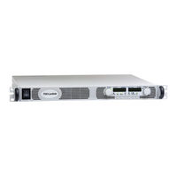
TDK-Lambda GENESYS 1500W Technical Manual (80 pages)
Programmable DC Power Supplies
Brand:
TDK-Lambda
| Category:
Power Supply
| Size: 1.69 MB
Table of Contents
Table of Contents
5
Warranty
9
Safety Instructions
10
German Safety Instructions
12
Chapter 1 General Information
14
User Manual Content
14
Introduction
14
General Description
14
Models Covered
14
Features and Options
14
Multiple Output Power System
15
Control Via the Serial Communication Port
15
Analog Voltage Programming and Monitoring
15
Parallel Operation
15
Output Connections
15
Cooling and Mechanical Construction
16
Accessories
16
Included Accessories
16
Optional Communication Cables
16
AC Cables
16
Chapter 2 Specifications
17
Output Rating
17
Input Characteristics
17
Constant Voltage Mode
17
Constant Current Mode
17
Analog Progrmaming and Monitoring
17
Programming and Readback
18
Protective Functions
18
Front Panel
18
Environmental Conditions
18
Mechanical
18
Safety/Ems
18
Supplemental Characteristics
19
Outline Drawings
20
Chapter 3 Installation
21
General
21
Preparation for Use
21
Initial Inspection
21
Rack Mounting
21
To Install the Power Supply in a Rack
21
Rack Mount Slides
22
Location Mounting and Cooling
22
Ac Source Requirements
22
Ac Input Power Connection
22
AC Input Connector, 1500W Models
23
AC Input Connector, 750W Models
23
AC Input Cord
23
AC Input Wire Connection, 1500W Models
23
Turn-On Checkout Procedure
24
General
24
Prior to Operation
24
Constant Voltage Check
25
Constant Current Check
25
OVP Check
25
UVL Check
25
Foldback Check
26
Address Setting
26
Baud Rate Setting
26
Connecting the Load
26
Load Wiring
26
Current Carrying Capacity
26
Wire Termination
27
Noise and Impedance Effects
28
Inductive Loads
28
Making the Load Connections
28
Connecting Single Loads, Local Sensing (Default)
31
Connecting Single Loads, Remote Sensing
31
Connecting Multiple Loads, Radial Distribution Method
31
Multiple Loads Connection with Distribution Terminals
32
Grounding Outputs
32
Local and Remote Sensing
33
Local Sensing
33
Remote Sensing
34
J2 Sense Connector Technical Information
34
Repackaging for Shipment
34
Chapter 4 Front and Rear Panel Controls and Connectors
35
Introduction
35
Front Panelcontrols and Indicators
35
Rear Panelconnections and Controls
37
Rear Panel Sw1 Setup Switch
38
SW1 Positions Functions
39
Resetting the SW1 Switch
39
Rear Panel J1 Programming and Monitoring Connector
40
Making J1 Connections
40
Chapter 5 Local Operation
42
Introduction
42
Standard Operation
42
Constant Voltage Mode
42
Automatic Crossover
43
Over Voltage Protection (Ovp)
43
Setting the OVP Level
43
Activated OVP Protection Indications
43
Resetting the OVP Circuit
43
Under Voltage Limit
44
Setting the UVL Level
44
Foldback Protection
44
Setting the Foldback Protection
44
Resetting Activated Foldback Protection
44
Output On/Off Control
44
Output Shut-Off (So) Control Via Rear Panel J1 Connector
44
Enable/Disable Control Via
45
CV/CC Signal
45
Ps Ok Signal
45
Safe Start and Auto-Restart Modes
46
Safe Start Mode
46
Over Temperature Protection (Otp)
46
Last Setting Memory
46
Series Operation
47
Series Connection for Increased Output Voltage
47
Series Connection for Positive and Negative Output Voltage
48
Parallel Operation
49
Basic Parallel Operation
49
Advanced Parallel Operation
50
Front Panel Locking
52
Unlocked Front Panel
52
Locked Front Panel
52
Chapter 6 Remote Analog Programming
53
Introduction
53
Local/Remote Analog Control
53
Local/Remote Analog Indication
53
Remote Monitoring of Output Voltage and Current
56
Chapter 7 Rs232 & Rs485 Remote Control
57
Introduction
57
Configuration
57
Default Setting
57
Address Setting
57
RS232 or RS485 Selection
57
Baud Rate Setting
57
Setting the Unit into Remote or Local Mode
57
Front Panel in Remote Mode
58
Rear Panel Rs232/485 Connector
58
MD MODE OPTION (Factory Installed)
59
MD Mode Description
59
MD Mode Enable - Serial Communication Mode
59
MD Mode SRQ
59
Communication Collisions
59
MD Mode SRQ Retransmission
59
Connecting Power Supplies to Rs232 or Rs485 Bus
60
Single Power Supply
60
Multi Power Supply Connection to RS232 or RS485 BUS
61
Communication Interface Protocol
61
Data Format
61
Addressing
61
End of Message
61
Command Repeat
61
Checksum
61
Acknowledge
61
Error Message
62
Backspace
62
Error Messages
62
Command Set Description
62
General Guides
62
Command Set Categories
62
Initialization Control Commands
63
ID Control Commands
63
Output Control Commands
63
Global Output Commands
65
General
65
Single Byte Commands
66
General
66
Global Commands Without Response
66
Global Commands with Response
66
Addressed Commands with Response
67
Addressed Commands Without Response
67
Status Control Commands
70
Status, Error and Srq Registers
70
General Description
70
Conditional Registers
71
Service Request: Enable and Event Registers
72
Serial Communication Test Set-Up
75
Chapter 8 Isolated Analog Programming Option
76
Introduction
76
Specifications
76
0-5V/0-10V Option
76
4-20Ma Option
76
Isolated Programming & Monitoring Connector
77
Setup and Operating Instructions
78
Setting up the Power Supply for 0-5V/0-10V Isolated Programming and Monitoring
78
Setting up the Power Supply for 4-20Ma Isolated Programming and Monitoring
78
Chapter 9 Maintenance
79
Introduction
79
Units under Warranty
79
Periodic Maintenance
79
Adjustment and Calibration
79
Parts Replacement and Repairs
79
Troubleshooting
79
Fuse Rating
80
Advertisement
Related Products
TDK-Lambda 102A
TDK-Lambda 152A
TDK-LAMBDA GEN 100-33ABCDE
TDK-LAMBDA GEN 15-220ABCDE
TDK-Lambda GENESYS 10KW
TDK-Lambda GENESYS 15KW
TDK-Lambda GENESYS 750W HALF RACK
TDK-Lambda Genesys GEN6-200
TDK-Lambda Genesys GEN6-100
TDK-Lambda Genesys GEN150-10
TDK-Lambda Categories
Power Supply
Media Converter
Cables and connectors
Portable Generator
Network Hardware
More TDK-Lambda Manuals
Login
Sign In
OR
Sign in with Facebook
Sign in with Google
Upload manual
Upload from disk
Upload from URL