Sign In
Upload
Manuals
Brands
Taylor-Dunn Manuals
Utility Vehicle
B0-200-00
Taylor-Dunn B0-200-00 Manuals
Manuals and User Guides for Taylor-Dunn B0-200-00. We have
2
Taylor-Dunn B0-200-00 manuals available for free PDF download: Operation, T Roubleshooting And Replacement Parts Manual, Service And Replacement Parts Manual
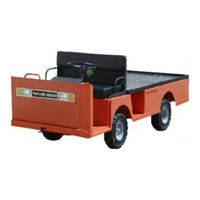
Taylor-Dunn B0-200-00 Operation, T Roubleshooting And Replacement Parts Manual (266 pages)
Brand:
Taylor-Dunn
| Category:
Utility Vehicle
| Size: 10.23 MB
Table of Contents
Table of Contents
7
About this Manual
8
Who Should Read this Manual
8
Responsibilities
8
How to Use this Manual
9
Conventions
9
How to Identify Your Vehicle
10
Taking Delivery of Your Vehicle
11
Sc1-00 Stock Chaser B2-48 with Stake Side Dump Bed Option
13
Standard Specifications Burden Carrier
14
Safety Rules and Guidelines
15
Driver Training Program
15
Driver Qualifications
15
Vehicle Controls
16
Dash Endingserial #179666
16
Key-Switch
16
Horn Switch
16
Battery Gauge / Smart View
16
Hour Meter
16
Accessory Switch (Optional)
16
Auxiliary Switches
16
Headlight Switch
16
Forward-Off-Reverse Switch
16
Dash Starting Serial #179667
17
Headlight Switch
17
Wiper Switch (Optional)
17
Strobe Switch (Optional)
17
Forward-Off-Reverse Switch
17
Hi-Low Switch (Optional)
17
Smart View Display
17
Horn Switch
17
Key-Switch
17
Battery Status Indicator, Analog
18
Battery Status Indicator, Digital Bargraph
18
Directional Signals (Optional)
18
Hazard Light Switch (Optional)
18
Accelerator Pedal
19
Foot Brake Pedal
19
Park Brake
19
Charger Interlock
19
Seat Interlock Switch
19
Steering
20
Reverse or Motion Alarm
20
Smart View Display
21
Fault Code Tables
23
Vehicle Operation Guidelines
24
Safety Guidelines
24
Starting
24
While Driving
24
Loading and Unloading
24
Towing Loads
24
Parking
25
Automatic Electric Park Brake
25
Towing this Vehicle
25
Charging Your Vehicle
26
Signet® Charger Operation, Model HB Series
26
Signet Charger Operation, Model HBS Series
26
New Battery Break in
27
Charging Time
27
Storing / Returning to Service
27
Storing Your Vehicle
27
Returning to Service
27
Periodic Maintenance Checklist
28
Standard Periodic Maintenance Schedule for the Smart View Display
29
Daily Visual Inspection
30
Maintenance Guidelines for Severe Duty Applications
30
Front Axle Service
35
Inspect the Front Wheel Bearings and King Pin
36
Adjust Front Wheel Bearings
37
Front Axle Removal and Installation
38
Removal
38
Installation
39
Front Axle Disassembly
40
Replace Front Wheel Bearings
41
Replace the King Pins and Bushings
43
Replace the Steering Knuckle
45
Steering Component Service
47
Front End Alignment
48
Inspect Ball Joints
52
Adjust the Steering Gear
53
Replace the Steering Shaft
55
Replace the Steering Wheel
57
Replace the Steering Gear
58
Replace the Ball Joints, Tie Rods, and Drag Link
59
Replacing the Drag Link
61
Replacing the Tie Rod
62
Center the Steering Gear
63
Pitman Shaft Alignment
63
Repair the Steering Gear
64
Exploded View of Steering Gear
67
Brake Service
69
Inspect the Service Brake
70
Disc Brake Pads (B 2-10, Front B 2-00 Optional)
70
Disc Brake Rotor (B 2-10, Front B 2-00 Optional)
71
Inspect the Parking Brake
72
Wheel Park Brake
72
Adjust the Service Brakes, B 2-10
73
Two or Four Wheel Hydraulic Disc Brakes
73
Adjust the Service Brakes, B 2-00
74
Adjust the Parking Brake
75
Wheel Park Brake, B 2-00
75
Wheel Park Brake, B 2-10
76
Check Master Cylinder Fluid
78
Bleed the Brakes
79
Flush the Brake System
81
Replace the Parking Brake Lining
82
Wheel Park Brake
82
Replace Front Brake Pads
83
Replace Rear Brake Pads or Shoes
85
Hydraulic Disc, B 2-10
85
Rear Drum Brakes, B 2-00
86
Replace the Wheel Cylinder
88
Disc Brake Body Assembly (Front or Rear)
88
Torque Spider. B 2-00
89
Repair the Disc Brake Body
90
Replace the Master Cylinder
92
Repair the Master Cylinder
94
Motor Service
95
Inspecting the Motor Brushes
96
Motors with Internal Cooling Fans
96
Motor Inspection
97
Motor Removal and Installation
97
Replacing the Brushes or Armature Bearing
101
Repairing the Commutator
102
Service Limits
104
Table of Contents
105
Troubleshooting
106
Remove/Install
106
Programming
107
Delta-Q
107
Signet
108
Delta-Q IC650
109
Transmission
111
Check Oil Level
112
Change Oil
113
Motor Removal and Installation
114
Rear Hub or Rotor
115
Removing and Installing the Rear Axles
116
Transmission Assembly
118
Remove and Install
118
Disassembly and Reassembly of the Primary Reduction Gear Case
120
Disassembling the 3Rd Member
123
Assembling the 3Rd Member
126
Pinion Bearing Preload
129
Pinion Gear Shimming Instructions
130
Setting the Pinion Gear Depth
130
Transmission 2 (B 2-00)
133
Check Oil Level
134
Change Oil
135
Motor
136
Removal
136
Installation
136
Rear Hub with Brake Drum
137
Removal and Installation
137
Rear Axle
138
Replace the Axle Bearing
140
Transmission
141
Removal
141
Installation
142
Differential Case
144
Disassemble
144
Assemble
147
Suspension
149
Replace the Rear Springs
150
Leaf (Elliptical)
150
Leaf (Elliptical)
151
Replace the Front Springs
151
Replace the Spring Bushings
152
Replace the Shocks
153
Front
153
Tires and Wheels
155
Tire Inflation
156
Tire Inspection
156
Replace the Tire/Wheel
157
Repair the Tire (Pneumatic)
158
Replace the Tire (Pneumatic)
159
Battery Service
161
Cleaning
162
Testing
163
Watering
165
Charging
166
Replacing (6-Volt Batteries Only)
167
Moist Charge Batteries
169
Storage and Returning to Service
170
Storage
170
Returning to Service
171
Illustrated Parts
181
Front Axle
182
Front Brakes
184
Steering Linkage
186
Steering Column
188
Front Suspension
190
Steering Gear
190
Rear Suspension, B 2-00
192
Rear Suspension, B 2-10
192
Front Shocks Option
194
Transmission Primary Gear Case, B 2-10
198
Transmission Differential Case, B 2-10
200
Rear Axle and Brakes, B 2-00
203
Rear Axle, B 2-10
203
Rear Brakes, B 2-10
204
Motor
206
Master Cylinder and Linkage
208
Hydraulic Brake Lines
210
Brake Linkage (Parking Brake), B 2-10
212
Brake Linkage (Parking Brake), B 2-00
214
Wheels and Tires
216
Instrument Panel Starting Serial Number 179667
218
Instrument Panel up to Serial Number 179666
218
Resetting the Smart View Display
218
Speed Control Panel
220
Chargers
221
Miscellaneous Electrical
226
Batteries
229
Seat Cushions, Lights, Deck and Frame
230
Decals
232
Fixed 2Nd and 3Rd Seat Option
234
Hitches
235
Cab and Cowl Windshield Frame Option
236
Dome Light Option
238
Foldaway 2Nd Seat Option
238
Windshield Wiper Option
238
Cab Doors
240
Mirrors
242
Strobe Light
242
Sun Tops
244
Optional Deckboards
248
Tool Box Doors Option
250
Rear Shocks (Optional)
251
Stake Side Options
252
12" Side Panel Option
254
Cargo Box Option
254
Ambulance Deck and Top
256
Appendix A: Special Tools
260
Appendix B: Suggested Torque
261
Hex Bolts
261
Other Bolts
261
Hex Nuts
262
Hex Lock Nuts (Stover)
262
Other Nuts
262
Suggested Torque Values (Non-Critical Hardware)
263
Appendix C: Brake Lining Handling Precautions
265
Advertisement
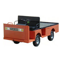
Taylor-Dunn B0-200-00 Service And Replacement Parts Manual (188 pages)
Brand:
Taylor-Dunn
| Category:
Utility Vehicle
| Size: 9.03 MB
Table of Contents
Master
5
Table of Contents
5
About this Manual
8
How to Use this Manual
8
Introduction
8
Who Should Read this Manual
8
Introduction
9
Conventions
9
Signal Words and Their Definitions
9
Responsibilities
10
How to Identify Your Vehicle
11
Web Site Registration
11
Service/Maintenance Guidelines
13
READ ME FIRST-Maintenance Guidelines and General Instructions
14
Service/Maintenance Guidelines
14
Vehicle Modifications
15
Replacement Parts
16
Using Non-OEM Replacement Components
16
Section 3
17
Preventative Maintenance
17
Pre-Operation Inspection
18
Maintenance Schedule
18
First 20 Hours of Operation
19
Every Week or 20 Hours
19
Every Month or 100 Hours
19
Every 3 Months or 300 Hours
19
Every 6 Months or 600 Hours)
19
Every Year or 1200 Hours
19
Every 2 Years or 2400 Hours
19
Preventative Maintenance
18
Daily Visual Inspection
18
Interlock Switch Inspection
20
Start Switch
20
High Pedal Disable (HPD)
20
Operator Presence Switch
20
Charger Interlock Switch
20
Special Tool List
21
Lubrication
25
Section 4
29
This Section Is One Section of a Complete Service
29
Front Axle
29
Manual. before Starting any Procedure, Read All
29
Warnings and Instructions that Are Located in the Service Guidelines Chapter
29
Front Axle
30
Remove
30
Installation
30
Disassemble
31
Adjust Front Wheel Bearings
32
Inspect Front Wheel Bearings
32
Front Wheel Alignment
33
Center the Steering
33
Replace Front Wheel Bearings
34
Replace Steering Knuckle
34
Replace King Pin/Bushings
35
Hardware Torque
36
Service Limits and Specifications
36
Toe in
36
Section 5
37
Transaxle-GT
37
Check Oil Level
38
Change Oil
38
Remove
39
Install
39
Axle Shaft
40
Remove
40
Install
40
Rear Hub, Rotor & Bearings
41
Motor, Remove
41
Primary Gear Case
42
Secondary Gear Case
43
Disassemble
43
Assemble
43
Pinion Bearing Preload
45
Pinion Gear Shimming Instructions
45
Set Pinion Bearing Preload
45
Hardware Torque
46
Transaxle-GT
38
Section 6
47
Transaxle-SD
47
Transaxle-SD
48
Check Oil Level
48
Change Oil
48
Remove
49
Install
49
Axle Shaft
50
Remove
50
Install
50
Rear Hub, Rotor & Bearings
51
Motor, Remove
51
Primary Reduction Gear Case
52
3Rd Member
54
Hardware Torque
54
Section 7
55
Drive Axle-D1
55
Drive Axle-D1
56
Check Oil Level
56
Change Oil
56
Drive Motor
57
Remove
57
Install
57
Differential Case
58
Disassemble
58
Assemble
60
Hardware Torque
61
Section 8
63
Steering
63
Inspect Ball Joints
64
Inspect Rod Ends
64
Adjust Steering Gear
65
Front Wheel Alignment
65
Replace Ball Joint
66
Replace Rod End
66
Replace Steering Shaft
67
Replace Steering Wheel
68
Steering Gear
69
Disassemble
69
Align Pitman Arm
70
Reassemble
70
Exploded View of Steering Gear
71
Hardware Torque
72
Steering
64
Section 9
73
Brakes-B-210
73
Brakes
74
General Guidelines and Safety
74
Front Brake
75
Service Limits
75
Inspection
75
Replace Pads
75
Rear Brake
76
Service Limits
76
Inspection
76
Replace Pads
76
Rebuild Disc Brake Body
77
Bleed System
78
Flush System
78
Master Cylinder
79
Add Fluid
79
Parking Brake
80
Inspect
80
Adjust
80
Service Limits
82
Hardware Torque
82
Section 10
83
Brakes-B-200
83
Brakes
84
General Guidelines and Safety
84
Front Disc Brake
85
Service Limits
85
Inspection
85
Replace Pads
85
Brake Adjustment
86
Service Brake
86
Mechanical and Hydraulic Brakes
86
Adjust the Service Brake Linkage
86
Parking Brake, Mechanical Brakes
86
Parking Brake, Hydraulic Brakes
87
Rear Drum Brake, Inspect/Replace
88
Service Limits
88
Inspection
88
Replace
88
Rebuild Disc Brake Body
89
Bleed System
90
Flush System
90
Master Cylinder
91
Add Fluid
91
Rebuild
91
Service Limits
92
Hardware Torque
92
Section 11
93
SEM Motor-B-210
93
SEM Motor-B-210
94
Disassemble
94
Remove/Install
94
Inspect
95
Brushes
95
Bearing
95
Commutator
95
Armature Windings
95
Field Windings
96
Repair
97
Service Limits
98
Section 12
99
Motor Controller
99
Motor Controller
100
Remove/Install
100
Inspect
100
Receptacles
100
Base Plate
100
Terminal Ends
100
R' Terminal
100
Repair/Programming
101
Programming
101
Troubleshooting
101
Hardware Torque
102
Wire Diagram
103
Section 13
107
Batteries
107
General Guidelines and Safety
108
Cleaning
109
Charging
109
Watering
109
Testing
110
Specific Gravity
110
Storing
110
Storage
110
Returning to Service
110
Remove/Install
111
Industrial Battery or Lift out Battery Pack
111
Individual Batteries
111
Hardware Torque
112
Batteries
108
Section 14
113
Tires & Wheels
113
Tires & Wheels
114
Inflation
114
Air Pressure
114
Tread Wear
115
Rotation
115
Changing Tire/Wheel Assembly
116
Replace the Tire (Pneumatic)
116
Repair the Tire (Pneumatic)
116
Hardware Torque
117
Suspension
119
Section 15
121
Hardware Information
121
Hardware Information
122
Torque Guidelines for Standard Hardware
122
Hardware Identification
122
Hex Lock Nuts (Stover)
123
Hex Nuts
123
Other Nuts
123
Generic Torque Values
124
Replacing Hardware
126
Replacement Parts
127
Ordering Parts for Your Vehicle
128
Replacement Parts
128
Taylor-Dunn Web Site Information
128
Axle Assembly, Front
130
Axle Shaft Assembly, B-210 Rear
132
Axle Shaft Assembly, B-200 Rear
133
Transaxle Assembly, B-200
134
Transaxle Assembly, B-210 Rear GT
136
Transaxle Assembly, B-210 Rear SD 3Rd Member
138
Transaxle Assembly, B-210 Rear Primary Reduction
139
Battery
140
Brakes, Brake Lines
142
Brakes, Master Cylinder & Linkage
144
Brakes, Front Axle
146
Brakes, B-210 Rear Axle
147
Brakes, B-200 Rear Axle
148
Brakes, B-200 Park Brake
150
Brakes, B-210 Park Brake
152
Charger, Signet
154
Charger, Delta Q
155
Charger, Summit
156
Control System, Motor Speed Control
157
Control System, Instrument Panel
158
Decals
160
Electrical, Miscellaneous
162
Electrical, Wiring
163
Frame, Cowl, Cab, Windshield Frame
164
Frame, Deckboards
165
Frame, Doors
166
Frame, Tool Box Doors
168
Frame, Stake Sides
169
Frame, Ambulance Deck
170
Frame, Tops
172
Hitches
174
Lights
175
Mirrors
175
Motor
176
Seats
177
Steering Gear
178
Steering Linkage
179
Steering Column
180
Suspension, Front
182
Suspension, B-210 Rear
183
Suspension, B-200 Rear
184
Wheels and Tires
185
Windshield Wiper
185
Advertisement
Related Products
Taylor-Dunn B0-254-48
Taylor-Dunn B0-248-48AC
Taylor-Dunn B0-254-48AC
Taylor-Dunn B0-248-36
Taylor-Dunn B0-248-48
Taylor-Dunn B0-254-36
Taylor-Dunn B0-210-36
Taylor-Dunn B0-210-36AMB
Taylor-Dunn B0-210-48
Taylor-Dunn B0-248-TT
Taylor-Dunn Categories
Utility Vehicle
Electric Vehicles
Trucks
Tractor
Automobile
More Taylor-Dunn Manuals
Login
Sign In
OR
Sign in with Facebook
Sign in with Google
Upload manual
Upload from disk
Upload from URL