Sign In
Upload
Manuals
Brands
Sun Microsystems Manuals
Server
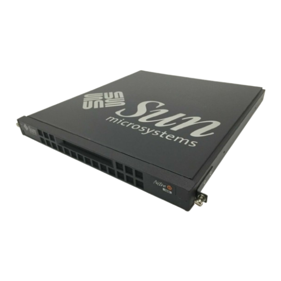
Netra t1 100
User Manuals: Sun Microsystems Netra t1 100 Server
Manuals and User Guides for Sun Microsystems Netra t1 100 Server. We have
1
Sun Microsystems Netra t1 100 Server manual available for free PDF download: User And Administration Manual
Sun Microsystems Netra t1 100 User And Administration Manual (154 pages)
Brand:
Sun Microsystems
| Category:
Server
| Size: 5 MB
Table of Contents
Table of Contents
3
How this Book Is Organized
15
Typographic Conventions
17
Safety Precautions
18
Sun Welcomes Your Comments
18
Part I. Installation and Configuration
21
1 Before You Begin
23
The Netra T1 Model 100/105 System
24
The Contents of the Ship Kit
25
Netra T1 Option Modules Available
25
TABLE 1-1 Contents of the Ship Kit
25
The Tools You Need for Installation
26
Your Operating Environment
26
The System's Tolerance of Different Environmental Conditions
26
Acoustic Noise Generated by the Netra T1
27
Environmental Compliance Information
27
Choosing between a Rack and a Cabinet
27
2 Operating Power and Cooling
29
Operating Power Statistics
30
TABLE 2-1 Operating Power Statistics for the Netra T1 Model 100 and Model 105
30
Calculating the Power Requirements for Your Netra T1
31
TABLE 2-2 Estimated Power Consumption of the Components of the Netra T1
31
Calculating the Heat to be Dissipated
32
3 Using DC Power
33
DC Source Site Requirements
34
Overcurrent Protection Requirements
35
TABLE 3-1 Overcurrent Protection Requirements
35
DC Connection Materials
36
Grounding
36
DC Supply and Ground Conductor
36
Assembling the DC Input Power Cable
37
To Assemble the DC Input Power Cable
37
FIGURE 3-1 Stripping the Insulation from the Wire
37
FIGURE 3-2 Opening the DC Connector Cage Clamp (Lever Method)
38
FIGURE 3-3 Opening the DC Connector Cage Clamp (Screwdriver Method)
39
FIGURE 3-4 Assembling the DC Input Power Cable
39
To Install the Strain Relief Housings
40
FIGURE 3-5 Inserting the Bottom Portion of the Strain Relief Housing
40
FIGURE 3-6 Routing the Wires out of the Strain Relief Housing
41
FIGURE 3-7 Securing the Wires to the Strain Relief Housing
41
FIGURE 3-8 Assembling the Strain Relief Housing
42
4 Installing Hardware Option Modules
43
Installing or Removing Hot-Pluggable Hard Disk Drives
44
FIGURE 4-1 Inserting Hard Disks into the Drive Bays
44
Opening the Netra T1 System
45
FIGURE 4-2 Using an Anti-Static Wrist Strap
45
FIGURE 4-3 Removing the Rack Mount Brackets
46
FIGURE 4-4 Removing the Top Cover
47
Identifying the Parts of the Netra T1
48
FIGURE 4-5 the Components of the Netra T1 System
48
Installing a CD-ROM Drive
49
FIGURE 4-6 Installing an Internal CD-ROM Drive
49
Installing Additional Memory
51
Installing a PCI Card
51
5 Installing the Netra T1 into a Rack
53
Installing into a Sun 72-Inch Rack
54
The 72-Inch Expansion Rack Mounting Kit
54
FIGURE 5-1 Cable Management Bracket
54
TABLE 5-1 72-Inch Expansion Rack Mounting Kit
54
To Assemble the Slides and Mount the System
55
FIGURE 5-2 Slide Mounts for Sun 72-Inch Expansion Rack
55
FIGURE 5-3 Fixing Slide Mounts into a Sun 72-Inch Expansion Rack - Rear View
56
FIGURE 5-5 Adjusting the Mount and Tightening the Thumbscrew
58
To Fit the Cable Management Bracket
59
FIGURE 5-6 the Cable Management Bracket Installed in a Sun 72-Inch Expansion Rack
59
Installing into a 19-Inch Rack
60
The 19-Inch Rack Mounting Kit
60
FIGURE 5-7 the Cable Management Bracket
60
TABLE 5-2 19-Inch Rack Mounting Kit
60
To Assemble the Slides and Mount the System
61
FIGURE 5-8 19-Inch Rack Slide Mounts
61
FIGURE 5-9 Fitting 19-Inch Slide Mounts to the Rack
62
FIGURE 5-10 Fitting the Netra T1 into a 19-Inch Rack
63
To Fit the Cable Management Bracket
64
FIGURE 5-11 the Cable Management Bracket Installed in a 19-Inch Rack
64
Installing into a Two-Post Relay Rack
65
The Fixed Mounting Bracket Kit
65
To Fit the Fixed Mounting Brackets
65
FIGURE 5-12 Removing the Thumbscrew Brackets
65
TABLE 5-3 Fixed Bracket Mounting Kit
65
FIGURE 5-13 Fitting the Fixed Mounting Brackets
66
FIGURE 5-14 the Netra T1 Installed in a Two-Post Rack
67
6 Connecting the Cables
69
Connecting the Cables to the Netra T1
70
FIGURE 6-1 Connecting the Netra T1 Model 100 System
70
FIGURE 6-2 Connecting the Netra T1 Model 105 System
70
Connecting the Power Cord(S)
72
FIGURE 6-3 Model 100: Connecting a DC Power Cord
72
FIGURE 6-4 Model 105: Connecting the AC Power Cord
72
Setting up Serial Connections
74
Cross-Overs for Connecting to a Terminal Server
75
FIGURE 6-5 Patch Panel Connection between a Cisco L2511 and a Netra T1 System
75
FIGURE 6-6 Serial Port Pins 1
76
TABLE 6-1 Pin Cross-Overs for Connecting to a Typical Terminal Server
76
Using a DB25 Adapter for Your Serial Link
77
FIGURE 6-7 Pins 1 to 8 on the Serial Ports
77
TABLE 6-2 Pin Cross-Overs in the Sun DB25 (25-Pin) Adapter
77
Using a DB9 Adapter for Your Serial Link
78
FIGURE 6-8 Pins 1 to 8 on the Serial Ports
78
TABLE 6-3 Pin Cross-Overs for a DB9 (9-Pin) Adapter
78
Settings for the Serial Connections
79
TABLE 6-4 Settings for Connecting to the Serial A/LOM or Serial B Port
79
7 Powering up the Netra T1
81
Powering up and Configuring for the First Time
82
Configuring Via a Terminal Server
82
Configuring from a Terminal or Workstation
82
To Power the System up for the First Time
83
Using the Power (On/Standby) Switch
85
FIGURE 7-1 Model 100 System Switch
85
FIGURE 7-2 Model 105 System Switch
85
8 Using Different Versions of Solaris
87
Installing Solaris Release 2.6
88
To Install Solaris 2.6 from the Cds
88
To Install Solaris 2.6 from the Network
89
Installing Solaris Release 7
90
The Patches You Need
90
Patch 108620-04: How to Boot from a CD
91
TABLE 8-1 Patches Required for Solaris 2.6 (5/98), or Solaris 7
91
Patch 108673-01: Setting Environment Variables
92
Maintenance and Management
95
9 Monitoring and Managing the System
97
What You Can Use the 'Lights-Out' Management (LOM) Facility for
98
How the LOM Device Sends Its Event Reports
99
When the Operating System Is Running and the Lomlited Daemon Is Installed and Running
99
When the Lomlited Daemon Is Not Running
99
Capturing LOM Event Reports Passively on the Serial A/LOM Port
100
Stopping the LOM from Sending Reports to the Serial a Port When the Daemon Is Not Running
100
Interrogating the LOM and Using It to Power up or Reset the System
101
Powering the System up and down
101
Resetting the System
102
Checking the Current Status of All Components Monitored by the LOM
102
FIGURE 9-1 the Environment Command Showing Fan 3 and DC Input Supply Faults
102
Viewing the LOM Device's Event Log
103
FIGURE 9-2 Sample LOM Device Event Log (Oldest Event Reported First)
103
Shortening the LOM Commands
104
A Listing of the LOM Commands
104
TABLE 9-1 LOM Commands
104
Configuring the LOM to Restart the System Automatically after a Lock-Up
106
Other Ways of Configuring the LOM
107
TABLE 9-2 LOM Configuration File Parameters
107
Utilites Associated with the LOM Device
108
Changing the First Character of the LOM Escape Sequence
108
The System's Front and Back Panel Leds
109
FIGURE 9-3 Front Panel Power and Fault Leds
109
FIGURE 9-4 Back Panel Ethernet Link, Power and Fault Leds
109
The Fans Monitored by the LOM Device
110
FIGURE 9-5 Locations of Fans 1, 2, and 3
110
10 Maintaining the System
111
Optional Accessories
112
TABLE 10-1 Orderable Options
112
Re-Using the Data in the Host ID Chip
113
FIGURE 10-1 Location of the Host ID Chip on the Motherboard
113
Replacing the Lithium Battery
114
FIGURE 10-2 Motherboard Components (Including the Lithium Battery)
114
Motherboard Jumpers
115
TABLE 10-2 Jumper Settings
115
FIGURE 10-3 Motherboard Jumper Locations
116
11 Troubleshooting
117
Appendices
121
Installing Additional Memory
123
Installing a Second Memory Board
124
Materials and Tools Required
124
FIGURE A-1 the 2-Stackable Memory Board Kit
124
To Install a Second Memory Board
125
FIGURE A-2 Lifting out the Processor Cover
125
FIGURE A-3 Removing the Mounting Screws from the Currently Installed Memory Board
126
FIGURE A-4 Removing the Old Screws and Inserting the New Ones
127
FIGURE A-5 Seating the Second Memory Board
128
Installing 4 X 256 Mbyte Memory Boards
129
Materials and Tools Required
129
FIGURE A-6 the 4-Stackable Memory Board Kit
130
To Install a Stack of Four Memory Boards
131
FIGURE A-7 Lifting out the Processor Cover
131
FIGURE A-8 Removing the Mounting Screws from the Currently Installed Memory Board
132
FIGURE A-9 Seating a Single Memory Board on the Netra T1'S Motherboard
133
FIGURE A-10 Stacking the Third Memory Board on Top of the Second
134
FIGURE A-11 Aligning the Four Plastic Spacers with the Mounting Holes
134
FIGURE A-12 Mounting the Second and Third Boards Onto the Base Memory Board
135
FIGURE A-13 Four Stacked Memory Boards on the Netra T1 Motherboard
136
FIGURE A-14 Dropping the Screws into the Aligned Mounting Holes
137
Installing a PCI Card
139
To Prepare the System for Installation
140
FIGURE B-1 Lifting out the Processor Cover
140
FIGURE B-2 Unclipping the Slide Retainer
141
FIGURE 11-1 Removing the Rear Screw and Pushing the MID Baffle Towards the Front
141
FIGURE B-3 Lifting out the MID Baffle
142
FIGURE B-4 Removing a PCI Card
142
To Install the Card
143
FIGURE B-5 Installing a PCI Card (Viewed from the Front)
143
FIGURE B-6 Replacing the MID Baffle
144
FIGURE B-7 Using the Slide Retainer to Hold the Corner of the PCI Card in Place
145
FIGURE B-8 Replacing the Processor Cover
146
FIGURE B-9 Replacing the Lid
147
FIGURE B-10 Re-Installing the Rack Mount Brackets
147
Index
149
Advertisement
Advertisement
Related Products
Sun Microsystems Sun Fire T1000
Sun Microsystems Netra T1 AC200
Sun Microsystems Netra T1 DC200
Sun Microsystems Netra t1 105
Sun Microsystems Netra t1 Series
Sun Microsystems SPARC T5120
Sun Microsystems Netra T4 DC100
Sun Microsystems SPARC Enterprise T5440
Sun Microsystems SPARC Enterprise T5140
Sun Microsystems SPARC Enterprise T5240
Sun Microsystems Categories
Server
Storage
Desktop
Computer Hardware
Adapter
More Sun Microsystems Manuals
Login
Sign In
OR
Sign in with Facebook
Sign in with Google
Upload manual
Upload from disk
Upload from URL