Sign In
Upload
Manuals
Brands
STMicroelectronics Manuals
Motherboard
EVALSTGAP4S
STMicroelectronics EVALSTGAP4S Manuals
Manuals and User Guides for STMicroelectronics EVALSTGAP4S. We have
1
STMicroelectronics EVALSTGAP4S manual available for free PDF download: User Manual
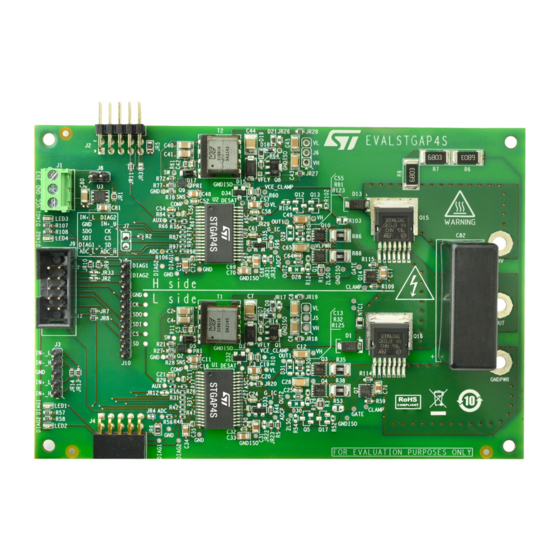
STMicroelectronics EVALSTGAP4S User Manual (28 pages)
For STGAP4S Advanced Galvanically Isolated Gate Driver
Brand:
STMicroelectronics
| Category:
Motherboard
| Size: 1 MB
Table of Contents
Figure 1. EVALSTGAP4S Evaluation Board
2
Safety and Operating Instructions
3
General Terms
3
Intended Use of Evaluation Board
3
Installing the Evaluation Board
3
Operating the Evaluation Board
4
Getting Started
5
EVALSTGAP4S with STEVAL-PCC009V2 and Evaluation Software
5
Check List
5
Single Board Setup Example
5
Multiple Board Setup Example
5
EVALSTGAP4S in Standalone Mode
6
Check List
6
Single Board Setup Example
6
Multiple Board Setup Example
6
Hardware Description and Configuration
7
Table 1. Connector Description
7
Table 2. Jumper Resistor Description
8
Figure 2. Connectors Location
8
Figure 3. Jumper Location - TOP Layer
9
Figure 4. Jumper Location - BOT Layer
9
Table 3. Jumper Configuration of 3V3IN Power Supply Source
10
Table 4. Jumper Configuration of VCC Power Supply Source
10
Table 5. Jumper Configuration of LOW-Side VH, VL Power Supply Source
10
Table 6. Jumper Configuration of HIGH-Side VH, VL Power Supply Source
10
Table 7. Jumper Configuration of PWM Input Signal (J3 Connector)
11
Table 8. Jumper Configuration of Diagnostic DIAG1 (J7, J2, J4 Connectors)
11
Table 9. Jumper Configuration of Diagnostic DIAG2 (J7, J2, J4 Connectors)
11
Table 10. Jumper Configuration of SPI Chain
12
Table 11. Jumper Configuration of LOW-Side ASC Bypass Jumper
12
Table 12. Jumper Configuration of HIGH-Side ASC Bypass Jumper
12
Table 13. Jumper Configuration of LOW-Side SENSE Bypass Jumper
12
Table 14. Jumper Configuration of HIGH-Side SENSE Bypass Jumper
12
Table 15. Jumper Configuration for LOW-Side DEFAULT Function (Operation Flow Chart)
12
Table 16. Jumper Configuration for HIGH-Side DEFAULT Function
13
Table 17. Test Points
13
Single Board
15
Figure 5. Single Board Configuration with Hardware Shoot-Through Protection
15
Figure 6. Half-Bridge Configuration with Hardware Shoot-Through Protection
16
Figure 7. Single Board Configuration with Independent Inputs
16
Multiple Boards Connection
17
Figure 8. Three Boards Connection
17
Power Supply Options
18
Figure 9. On-Board Linear Regulator (Default Setting)
18
Figure 10. 3V3IN Fed by External Power Supply
18
Figure 11. Flyback Power Supply (Default Setting)
19
Figure 12. VH, VL Fed by External Power Supply
19
EVALSTGAP4S Schematic Diagram
20
Figure 13. EVALSTGAP4S Schematic Diagram - Connectors
20
Figure 14. EVALSTGAP4S Schematic Diagram - Low-Side
21
Figure 15. EVALSTGAP4S Schematic Diagram - High-Side
22
Figure 16. EVALSTGAP4S Schematic Diagram - Power Stage
23
Revision History
24
Table 18. Document Revision History
24
Table of Contents
25
List of Tables
26
List of Figures
27
Advertisement
Advertisement
Related Products
STMicroelectronics EVALSPEAr320CPU
STMicroelectronics AEK-POW-BMS63EN
STMicroelectronics ATLASISABD
STMicroelectronics ATLASLBBD
STMicroelectronics L62 Series
STMicroelectronics LED7707
STMicroelectronics MB467
STMicroelectronics Categories
Motherboard
Microcontrollers
Computer Hardware
Controller
Control Unit
More STMicroelectronics Manuals
Login
Sign In
OR
Sign in with Facebook
Sign in with Google
Upload manual
Upload from disk
Upload from URL